Utilizing Directional Antennas in Ad Hoc Networks UDAAN





- Slides: 106
Utilizing Directional Antennas in Ad Hoc Networks (UDAAN) Nitin H. Vaidya University of Illinois at Urbana-Champaign Joint work with Romit Roy Choudhury Xue Yang University of Illinois Ramanathan BBN Technologies
Broad Theme • Impact of physical layer mechanisms on upper layers – Adaptive modulation – Power control – Directional antennas
UDAAN • DARPA FCS communications project • Focus on exploiting directional antennas for ad hoc networking
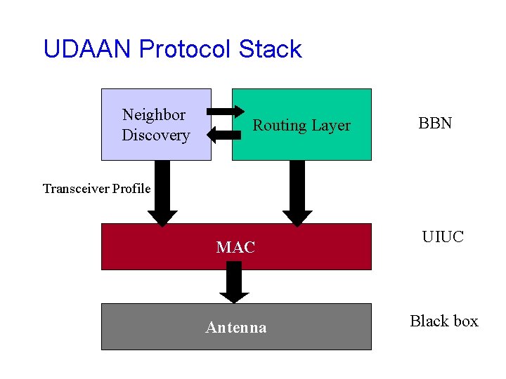
UDAAN Protocol Stack Neighbor Discovery Routing Layer BBN Transceiver Profile MAC Antenna UIUC Black box
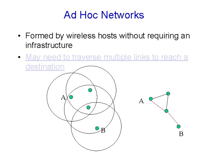
Ad Hoc Networks • Formed by wireless hosts without requiring an infrastructure • May need to traverse multiple links to reach a destination A A B B
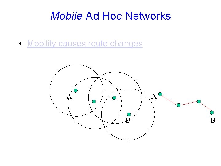
Mobile Ad Hoc Networks • Mobility causes route changes A A B B
Why Ad Hoc Networks ? • Ease of deployment • Decreased dependence on infrastructure
Antennas • Wireless hosts typically use single-mode antennas • Typically, the single-mode = omni-directional • Much of the discussion here applies when the single-mode is not omni-directional
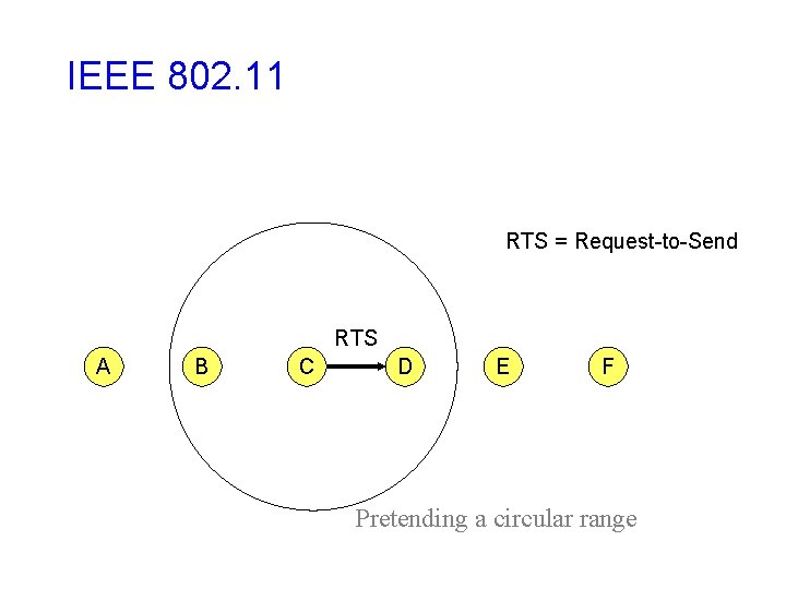
IEEE 802. 11 RTS = Request-to-Send RTS A B C D E F Pretending a circular range
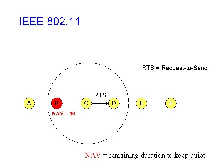
IEEE 802. 11 RTS = Request-to-Send RTS A B C D E F NAV = 10 NAV = remaining duration to keep quiet
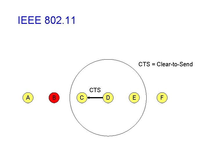
IEEE 802. 11 CTS = Clear-to-Send CTS A B C D E F
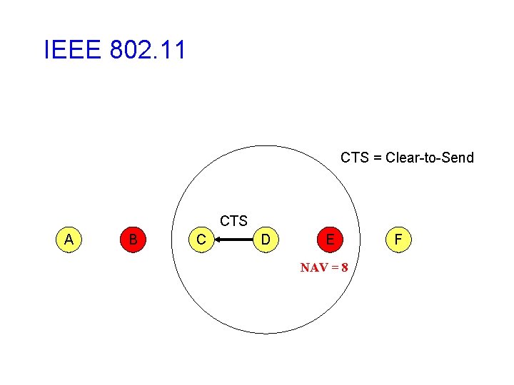
IEEE 802. 11 CTS = Clear-to-Send CTS A B C D E NAV = 8 F
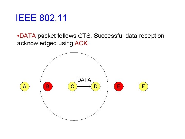
IEEE 802. 11 • DATA packet follows CTS. Successful data reception acknowledged using ACK. DATA A B C D E F
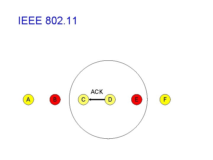
IEEE 802. 11 ACK A B C D E F
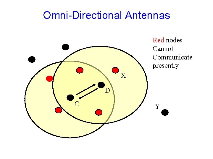
Omni-Directional Antennas Red nodes Cannot Communicate presently X D C Y
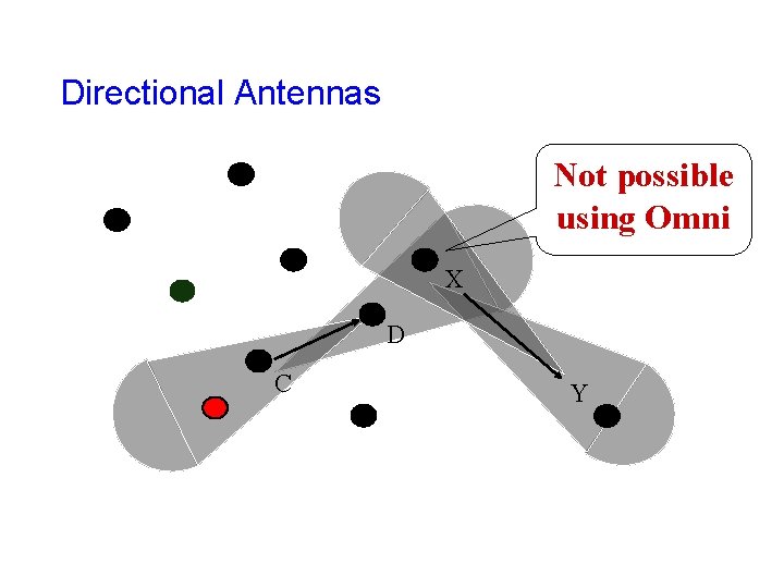
Directional Antennas Not possible using Omni X D C Y
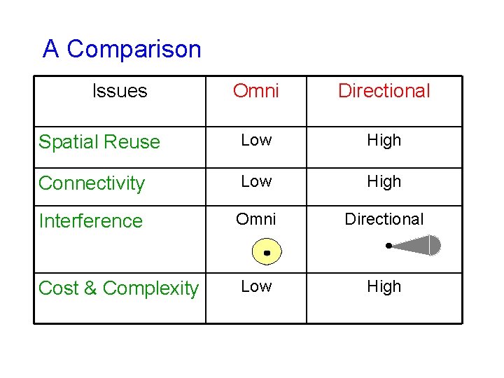
A Comparison Issues Omni Directional Spatial Reuse Low High Connectivity Low High Interference Omni Directional Cost & Complexity Low High
Question • How to exploit directional antennas in ad hoc networks ? – Medium access control – Routing
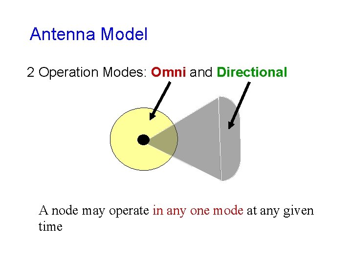
Antenna Model 2 Operation Modes: Omni and Directional A node may operate in any one mode at any given time
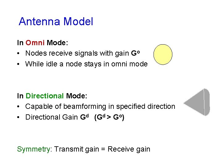
Antenna Model In Omni Mode: • Nodes receive signals with gain Go • While idle a node stays in omni mode In Directional Mode: • Capable of beamforming in specified direction • Directional Gain Gd (Gd > Go) Symmetry: Transmit gain = Receive gain
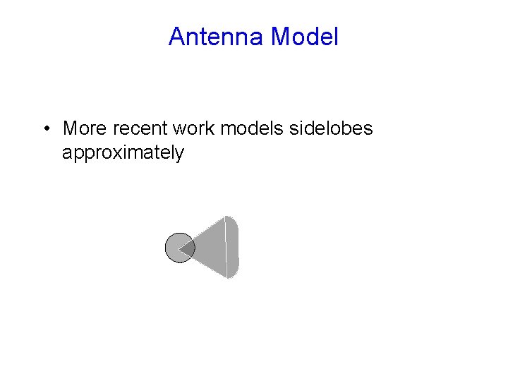
Antenna Model • More recent work models sidelobes approximately
Caveat Abstract antenna model Results only as good as the abstraction Need more accurate antenna models
Directional Communication Received Power (Transmit power) *(Tx Gain) * (Rx Gain) Directional gain is higher
Potential Benefits of Directional Antennas • Increase “range”, keeping transmit power constant • Reduce transmit power, keeping range comparable with omni mode • Realizing only the second benefit easier
Neighbors • Notion of a “neighbor” needs to be reconsidered – Similarly, the notion of a “broadcast” must also be reconsidered
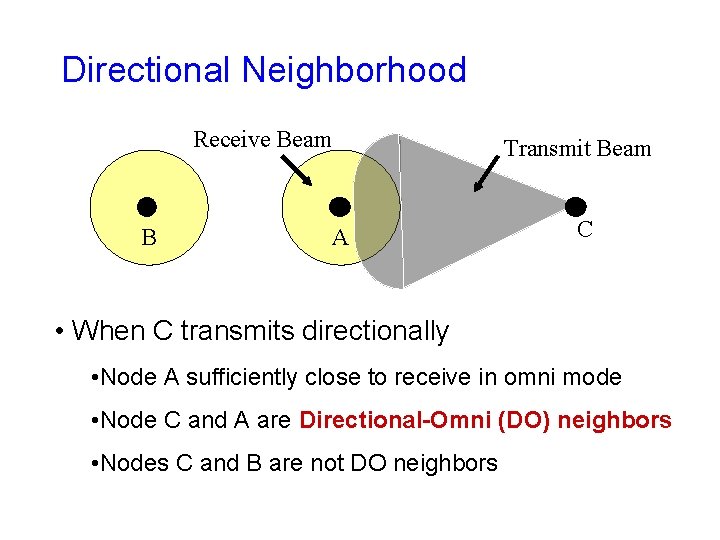
Directional Neighborhood Receive Beam B Transmit Beam A C • When C transmits directionally • Node A sufficiently close to receive in omni mode • Node C and A are Directional-Omni (DO) neighbors • Nodes C and B are not DO neighbors
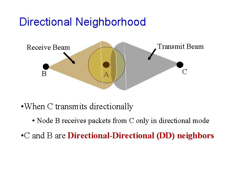
Directional Neighborhood Transmit Beam Receive Beam B A C • When C transmits directionally • Node B receives packets from C only in directional mode • C and B are Directional-Directional (DD) neighbors
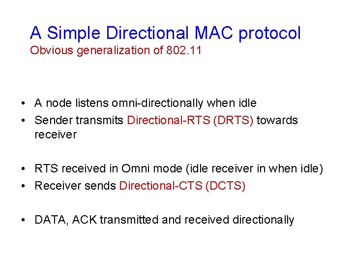
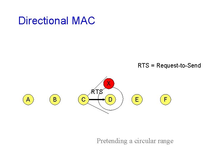
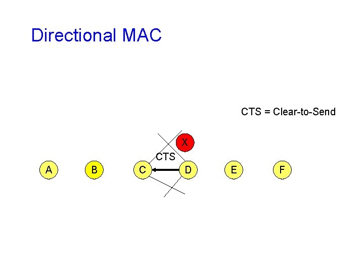
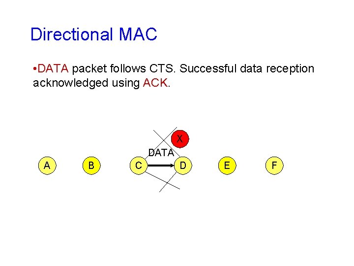
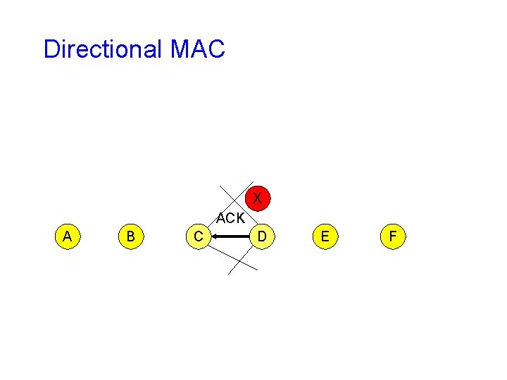
A Simple Directional MAC protocol Obvious generalization of 802. 11 • A node listens omni-directionally when idle • Sender transmits Directional-RTS (DRTS) towards receiver • RTS received in Omni mode (idle receiver in when idle) • Receiver sends Directional-CTS (DCTS) • DATA, ACK transmitted and received directionally
Directional MAC RTS = Request-to-Send X RTS A B C D E F Pretending a circular range
Directional MAC CTS = Clear-to-Send X CTS A B C D E F
Directional MAC • DATA packet follows CTS. Successful data reception acknowledged using ACK. X DATA A B C D E F
Directional MAC X ACK A B C D E F
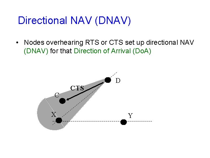
Directional NAV (DNAV) • Nodes overhearing RTS or CTS set up directional NAV (DNAV) for that Direction of Arrival (Do. A) C X CTS D Y
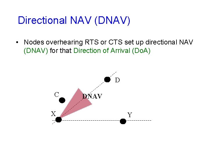
Directional NAV (DNAV) • Nodes overhearing RTS or CTS set up directional NAV (DNAV) for that Direction of Arrival (Do. A) D C X DNAV Y
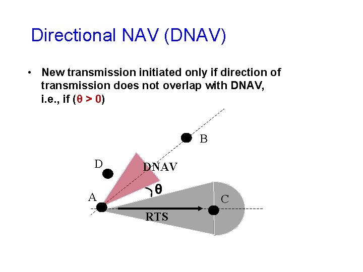
Directional NAV (DNAV) • New transmission initiated only if direction of transmission does not overlap with DNAV, i. e. , if (θ > 0) B D A DNAV θ RTS C
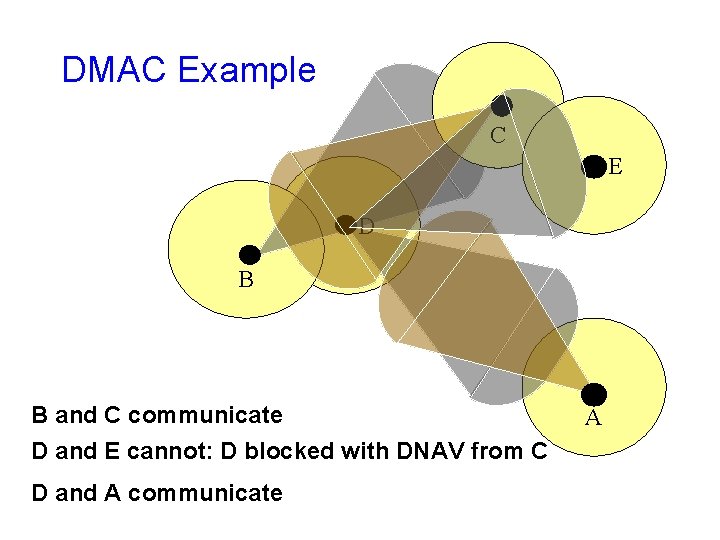
DMAC Example C E D B B and C communicate D and E cannot: D blocked with DNAV from C D and A communicate A
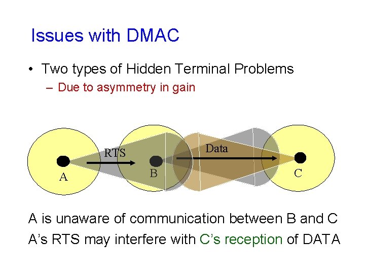
Issues with DMAC • Two types of Hidden Terminal Problems – Due to asymmetry in gain Data RTS A B C A is unaware of communication between B and C A’s RTS may interfere with C’s reception of DATA
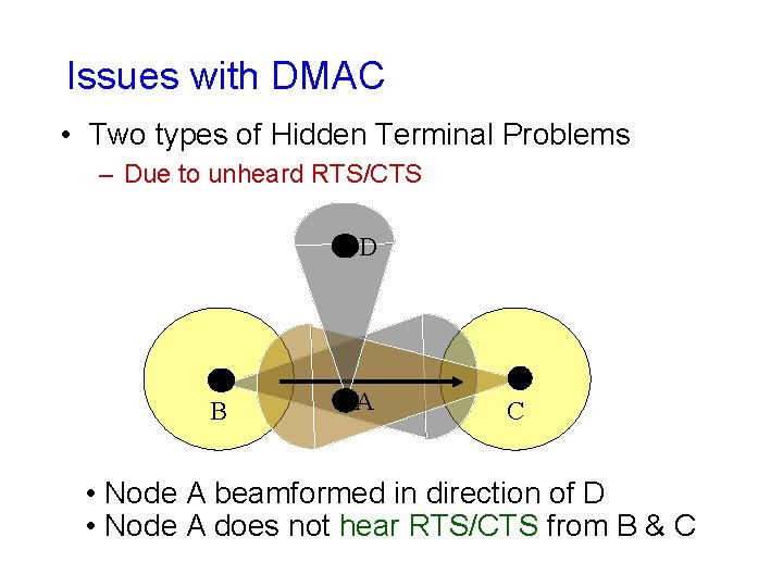
Issues with DMAC • Two types of Hidden Terminal Problems – Due to unheard RTS/CTS D B A C • Node A beamformed in direction of D • Node A does not hear RTS/CTS from B & C
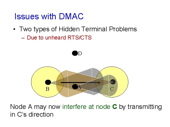
Issues with DMAC • Two types of Hidden Terminal Problems – Due to unheard RTS/CTS D B A C Node A may now interfere at node C by transmitting in C’s direction
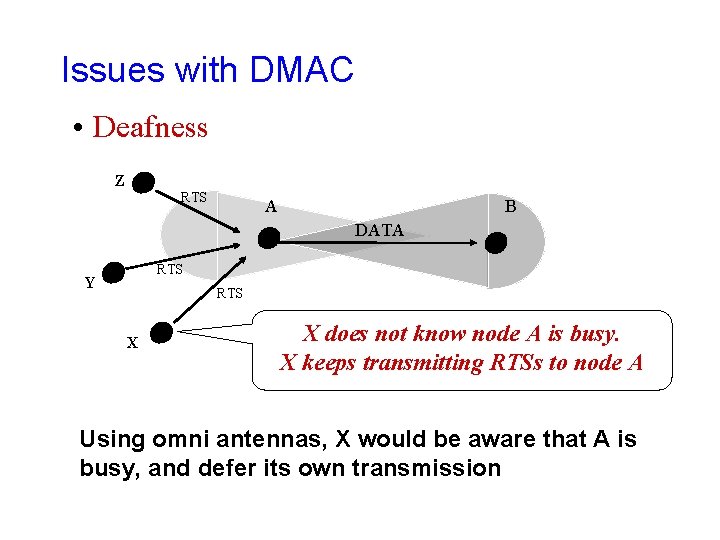
Issues with DMAC • Deafness Z RTS A B DATA RTS Y RTS X X does not know node A is busy. X keeps transmitting RTSs to node A Using omni antennas, X would be aware that A is busy, and defer its own transmission
Issues with DMAC • Uses DO links, but not DD links
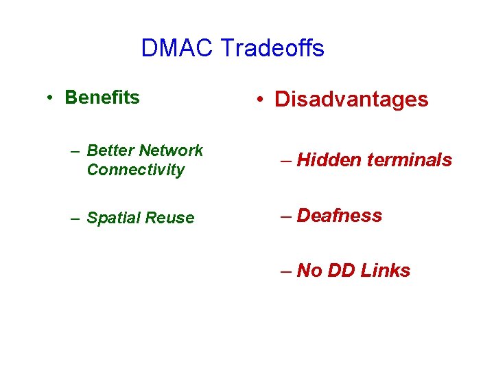
DMAC Tradeoffs • Benefits • Disadvantages – Better Network Connectivity – Hidden terminals – Spatial Reuse – Deafness – No DD Links
Enhancing DMAC • Are improvements possible to make DMAC more effective ? • One possible improvement: Make Use of DD Links
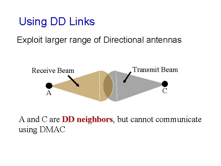
Using DD Links Exploit larger range of Directional antennas Receive Beam A Transmit Beam C A and C are DD neighbors, but cannot communicate using DMAC
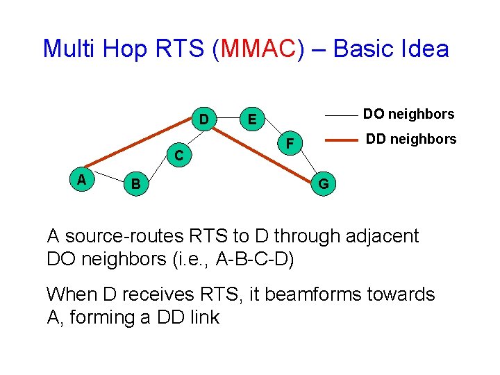
Multi Hop RTS (MMAC) – Basic Idea D C A B DO neighbors E DD neighbors F G A source-routes RTS to D through adjacent DO neighbors (i. e. , A-B-C-D) When D receives RTS, it beamforms towards A, forming a DD link
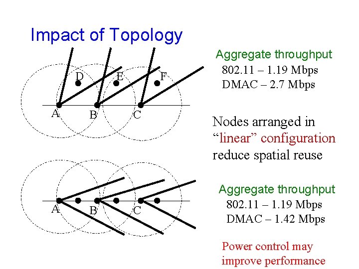
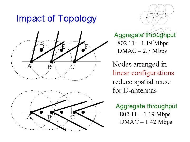
Impact of Topology D A A E B B F C C Aggregate throughput 802. 11 – 1. 19 Mbps DMAC – 2. 7 Mbps Nodes arranged in “linear” configuration reduce spatial reuse Aggregate throughput 802. 11 – 1. 19 Mbps DMAC – 1. 42 Mbps Power control may improve performance
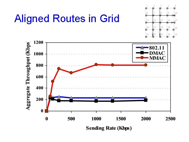
Aligned Routes in Grid
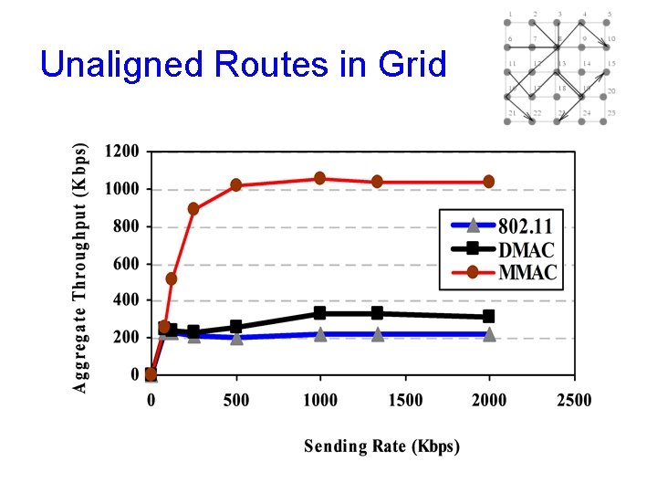
Unaligned Routes in Grid
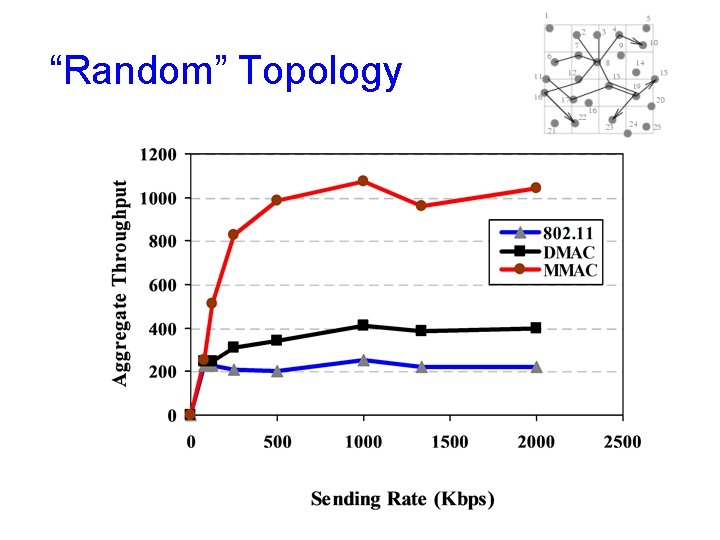
“Random” Topology
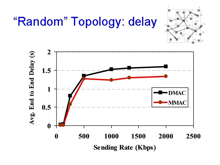
“Random” Topology: delay
MMAC - Concerns • Lower probability of RTS delivery • Multi-hop RTS may not reach DD neighbor due to deafness or collision • Neighbor discovery overheads may offset the advantages of MMAC
Directional MAC: Summary • Directional MAC protocols show improvement in aggregate throughput and delay – But not always • Performance dependent on topology – “Random” topology aids directional communication
Routing
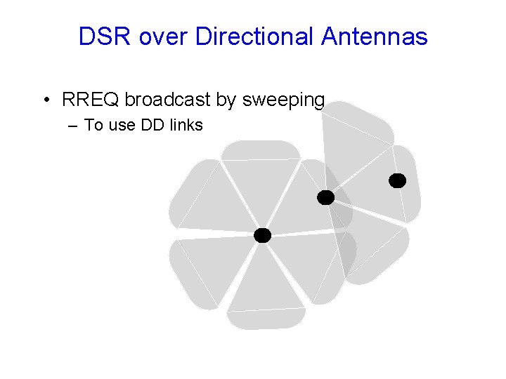
Routing Protocols • Many routing protocols for ad hoc networks rely on broadcast messages – For instance, flood of route requests (RREQ) • Using omni antennas for broadcast will not discover DD links • Need to implement broadcast using directional transmissions
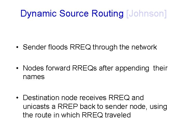
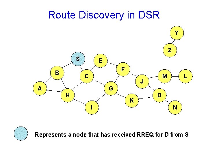
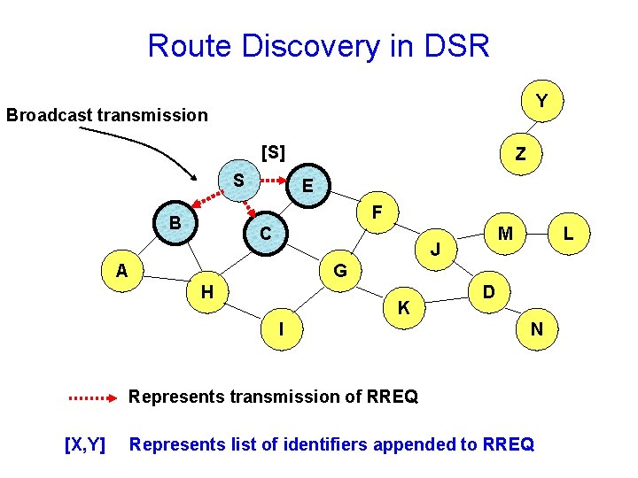
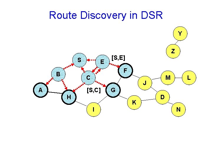
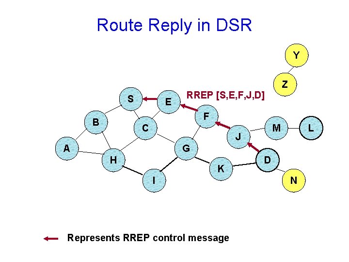
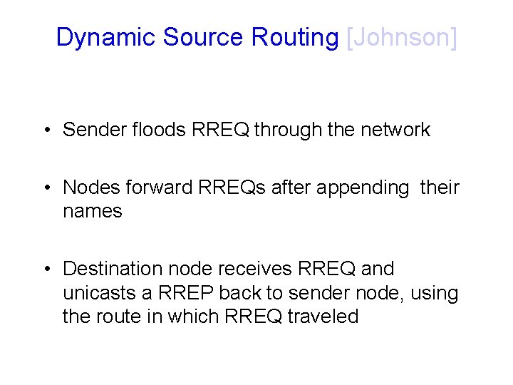
Dynamic Source Routing [Johnson] • Sender floods RREQ through the network • Nodes forward RREQs after appending their names • Destination node receives RREQ and unicasts a RREP back to sender node, using the route in which RREQ traveled
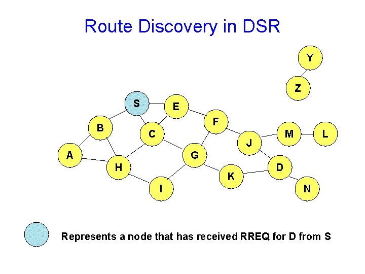
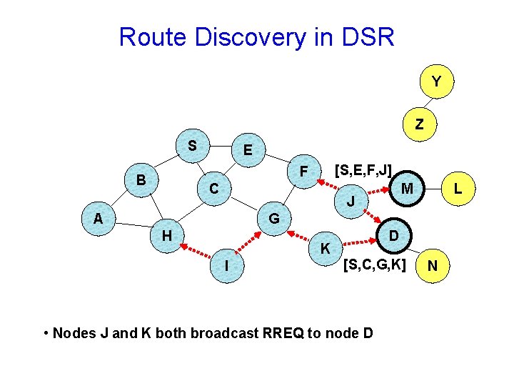
Route Discovery in DSR Y Z S E F B C M J A L G H K I D N Represents a node that has received RREQ for D from S
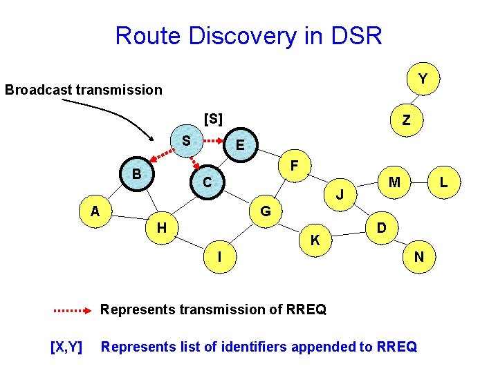
Route Discovery in DSR Y Broadcast transmission [S] S Z E F B C M J A L G H K I D N Represents transmission of RREQ [X, Y] Represents list of identifiers appended to RREQ
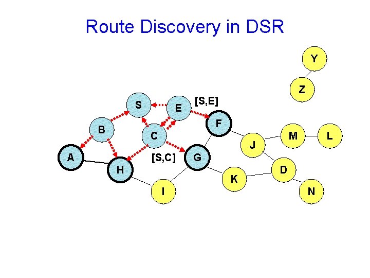
Route Discovery in DSR Y S E Z [S, E] F B C A M J [S, C] H G K I L D N
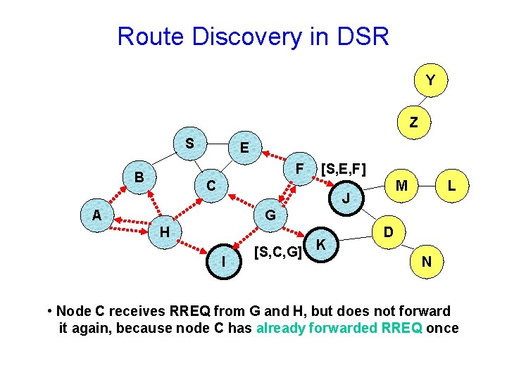
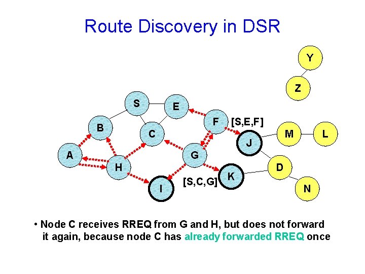
Route Discovery in DSR Y Z S E F B [S, E, F] C M J A L G H I [S, C, G] K D N • Node C receives RREQ from G and H, but does not forward it again, because node C has already forwarded RREQ once
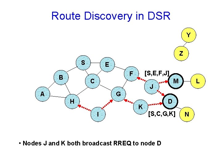
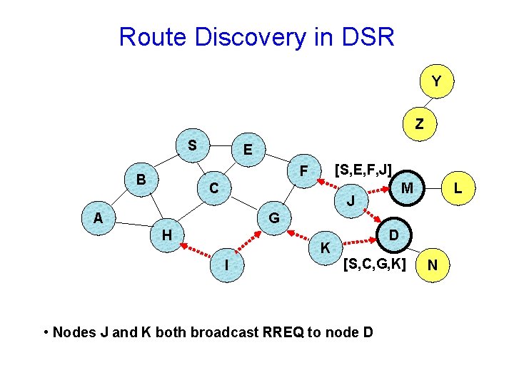
Route Discovery in DSR Y Z S E [S, E, F, J] F B C M J A L G H K I D [S, C, G, K] • Nodes J and K both broadcast RREQ to node D N
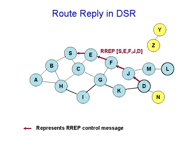
Route Reply in DSR Y S E Z RREP [S, E, F, J, D] F B C M J A L G H K I Represents RREP control message D N
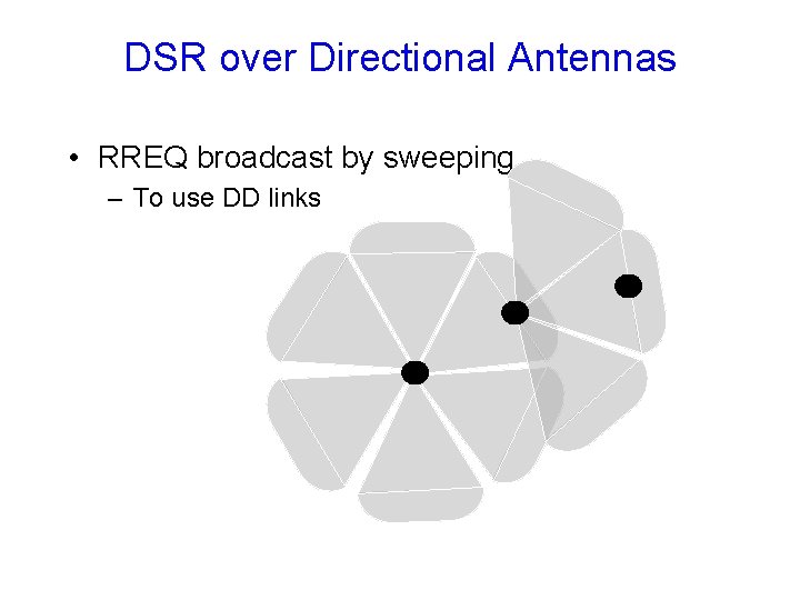
DSR over Directional Antennas • RREQ broadcast by sweeping – To use DD links
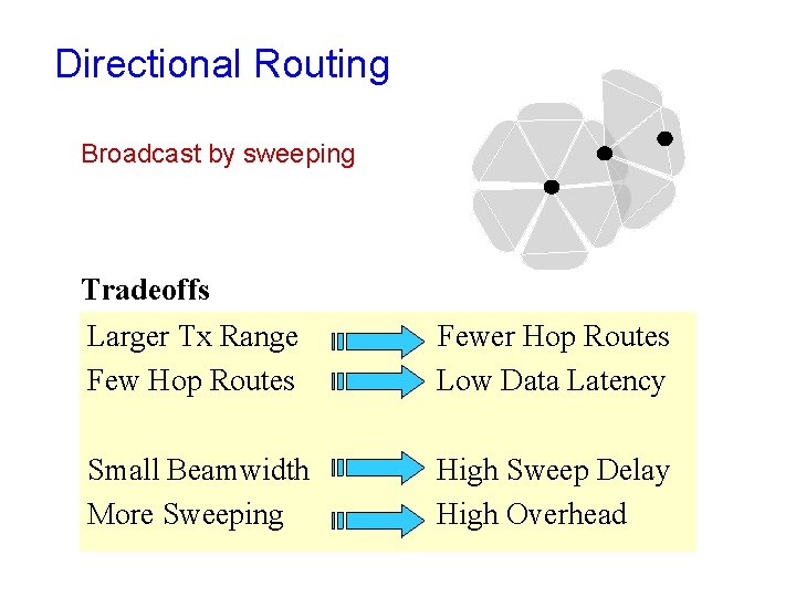
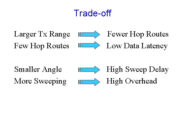
Directional Routing Broadcast by sweeping Tradeoffs Larger Tx Range Few Hop Routes Fewer Hop Routes Low Data Latency Small Beamwidth More Sweeping High Sweep Delay High Overhead
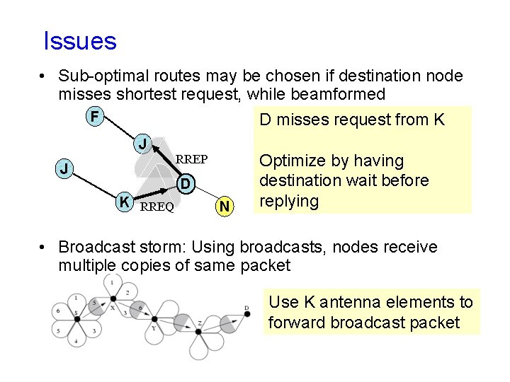
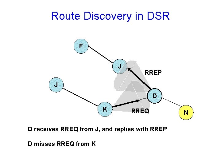
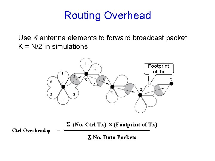
Issues • Sub-optimal routes may be chosen if destination node misses shortest request, while beamformed F D misses request from K J RREP J D K RREQ N Optimize by having destination wait before replying • Broadcast storm: Using broadcasts, nodes receive multiple copies of same packet Use K antenna elements to forward broadcast packet
Performance • Preliminary results indicate that routing performance can be improved using directional antennas
Conclusion • Directional antennas can potentially benefit • But also create difficulties in protocol design • Other issues – – Power control Need better models for directional antennas Capacity analysis Multi-packet reception Need to better understand physical layer
Thanks! Related papers at www. crhc. uiuc. edu/~nhv
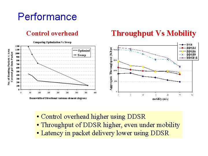
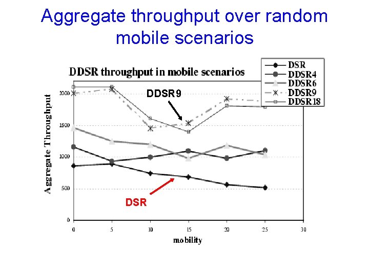
Performance Control overhead Throughput Vs Mobility • Control overhead higher using DDSR • Throughput of DDSR higher, even under mobility • Latency in packet delivery lower using DDSR
Routing using Directional Antennas
Dynamic Source Routing [Johnson] • Sender floods RREQ through the network • Nodes forward RREQs after appending their names • Destination node receives RREQ and unicasts a RREP back to sender node, using the route in which RREQ traveled
Route Discovery in DSR Y Z S E F B C M J A L G H K I D N Represents a node that has received RREQ for D from S
Route Discovery in DSR Y Broadcast transmission [S] S Z E F B C M J A L G H K I D N Represents transmission of RREQ [X, Y] Represents list of identifiers appended to RREQ
Route Discovery in DSR Y S E Z [S, E] F B C A M J [S, C] H G K I L D N
Route Discovery in DSR Y Z S E F B [S, E, F] C M J A L G H I [S, C, G] K D N • Node C receives RREQ from G and H, but does not forward it again, because node C has already forwarded RREQ once
Route Discovery in DSR Y Z S E [S, E, F, J] F B C M J A L G H K I D [S, C, G, K] • Nodes J and K both broadcast RREQ to node D N
Route Reply in DSR Y S E Z RREP [S, E, F, J, D] F B C M J A L G H K I Represents RREP control message D N
DSR over Directional Antennas • RREQ broadcast by sweeping – To use DD links
Route Discovery in DSR Y Z S E [S, E, F, J] F B C M J A L G H K I D [S, C, G, K] • Nodes J and K both broadcast RREQ to node D N
Trade-off Larger Tx Range Few Hop Routes Fewer Hop Routes Low Data Latency Smaller Angle More Sweeping High Sweep Delay High Overhead
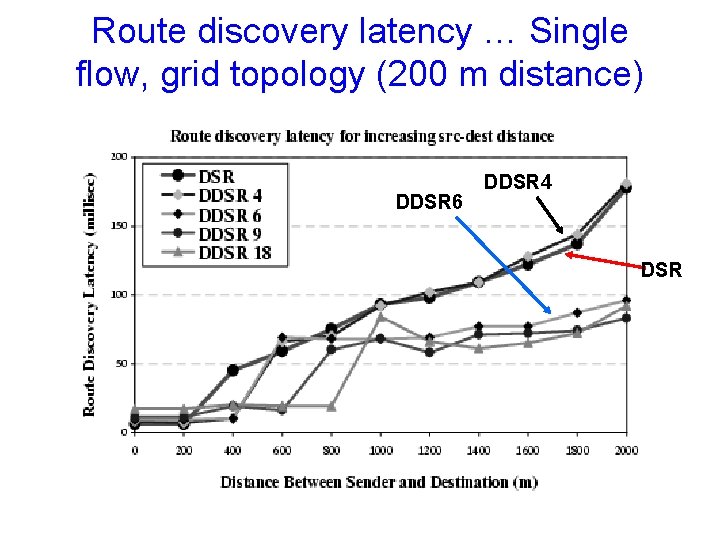
Route discovery latency … Single flow, grid topology (200 m distance) DDSR 6 DDSR 4 DSR
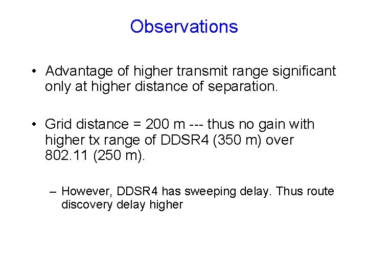
Observations • Advantage of higher transmit range significant only at higher distance of separation. • Grid distance = 200 m --- thus no gain with higher tx range of DDSR 4 (350 m) over 802. 11 (250 m). – However, DDSR 4 has sweeping delay. Thus route discovery delay higher
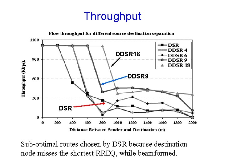
Throughput DDSR 18 DDSR 9 DSR Sub-optimal routes chosen by DSR because destination node misses the shortest RREQ, while beamformed.
Route Discovery in DSR F J RREP J D K RREQ D receives RREQ from J, and replies with RREP D misses RREQ from K N
Delayed RREP Optimization • Due to sweeping – earliest RREQ need not have traversed shortest hop path. – RREQ packets sent to different neighbors at different points of time • If destination replies to first arriving RREP, it might miss shorter-path RREQ • Optimize by having DSR destination wait before replying with RREP
Routing Overhead • Using omni broadcast, nodes receive multiple copies of same packet - Redundant !!! • Broadcast Storm Problem • Using directional Antennas – can do better ?
Routing Overhead Use K antenna elements to forward broadcast packet. K = N/2 in simulations Footprint of Tx Ctrl Overhead = (No. Ctrl Tx) (Footprint of Tx) No. Data Packets
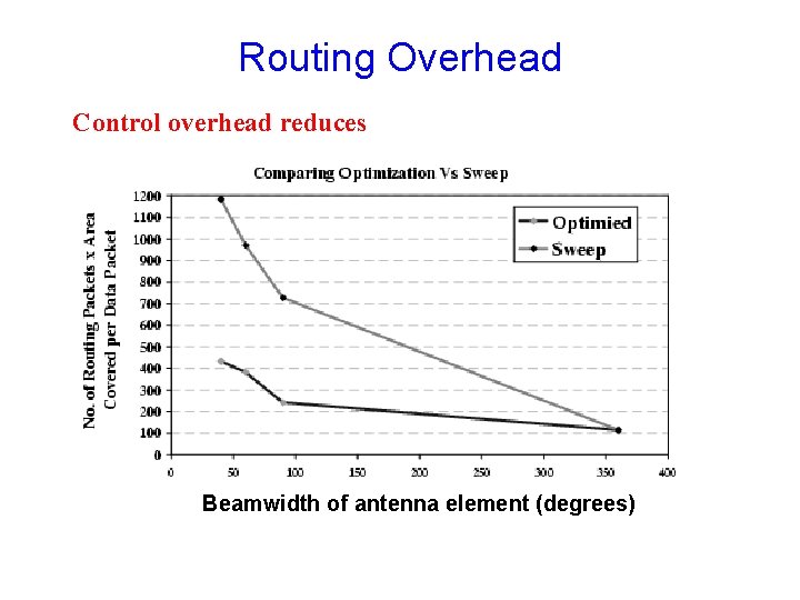
Routing Overhead Control overhead reduces Beamwidth of antenna element (degrees)
Directional Antennas over mobile scenarios • Frequent Link failures – Communicating nodes move out of transmission range • Possibility of handoff – Communicating nodes move from one antenna to another while communicating
Directional Antennas over mobile scenarios • Link lifetime increases using directional antennas. – Higher transmission range - link failures are less frequent • Handoff handled at MAC layer – If no response to RTS, MAC layer uses N adjacent antenna elements to transmit same packet – Route error avoided if communication re-established.
Aggregate throughput over random mobile scenarios DDSR 9 DSR
Observations • Randomness in topology aids DDSR. • Voids in network topology bridged by higher transmission range (prevents partition) • Higher transmission range increases link lifetime – reduces frequency of link failure under mobility • Antenna handoff due to nodes crossing antenna elements – not too serious
Conclusion • Directional antennas can improve performance • But suitable protocol adaptations necessary • Also need to use suitable antenna models • … plenty of problems remain
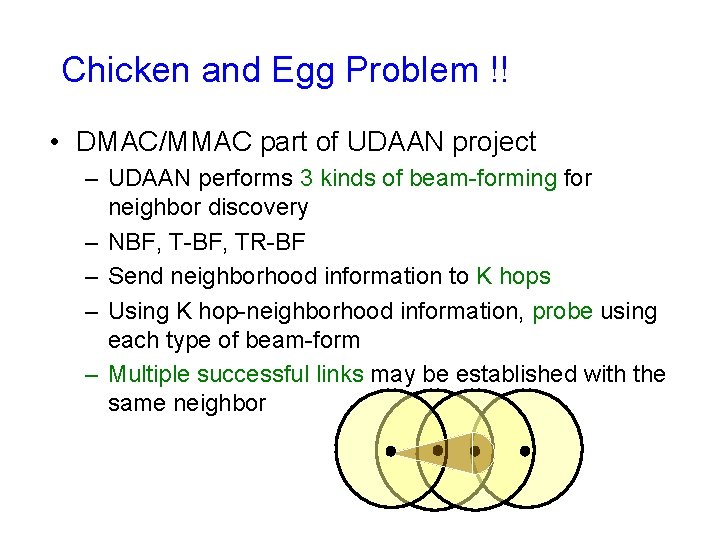
Chicken and Egg Problem !! • DMAC/MMAC part of UDAAN project – UDAAN performs 3 kinds of beam-forming for neighbor discovery – NBF, T-BF, TR-BF – Send neighborhood information to K hops – Using K hop-neighborhood information, probe using each type of beam-form – Multiple successful links may be established with the same neighbor
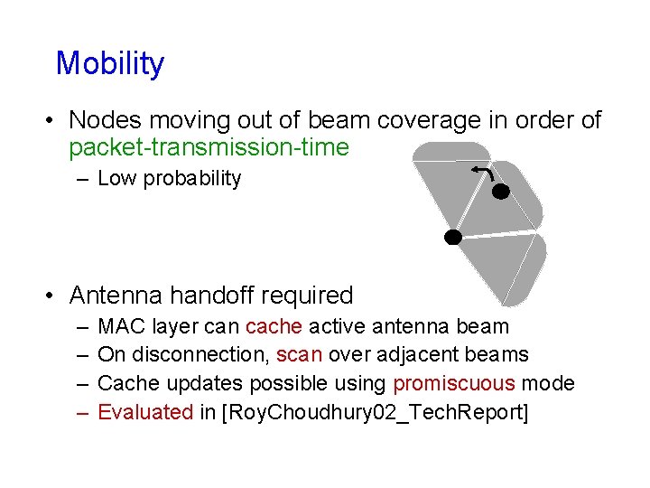
Mobility • Nodes moving out of beam coverage in order of packet-transmission-time – Low probability • Antenna handoff required – – MAC layer can cache active antenna beam On disconnection, scan over adjacent beams Cache updates possible using promiscuous mode Evaluated in [Roy. Choudhury 02_Tech. Report]
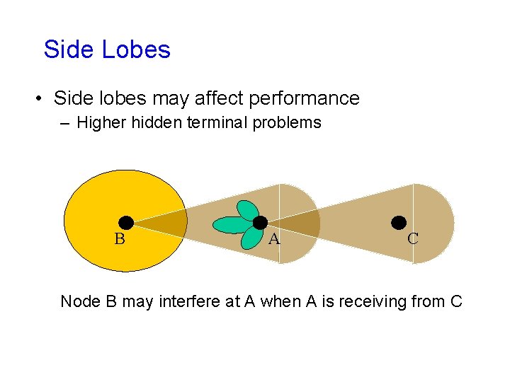
Side Lobes • Side lobes may affect performance – Higher hidden terminal problems B A C Node B may interfere at A when A is receiving from C
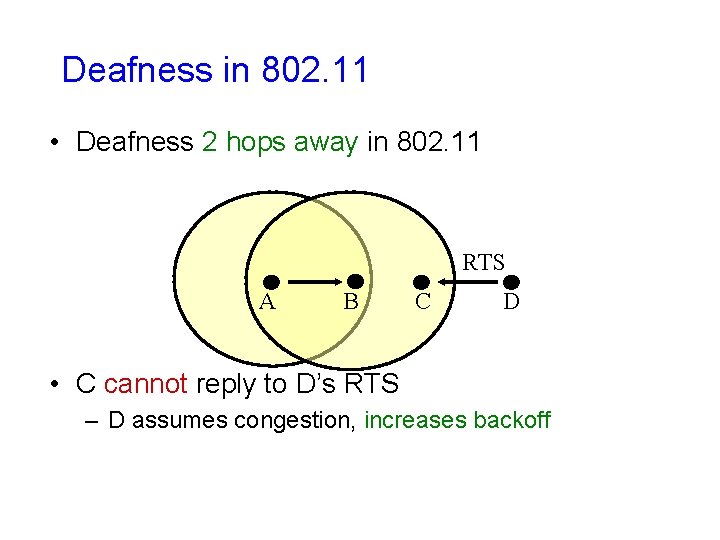
Deafness in 802. 11 • Deafness 2 hops away in 802. 11 RTS A B C D • C cannot reply to D’s RTS – D assumes congestion, increases backoff
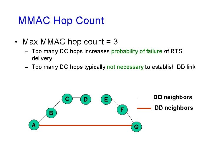
MMAC Hop Count • Max MMAC hop count = 3 – Too many DO hops increases probability of failure of RTS delivery – Too many DO hops typically not necessary to establish DD link C B A D DO neighbors E DD neighbors F G
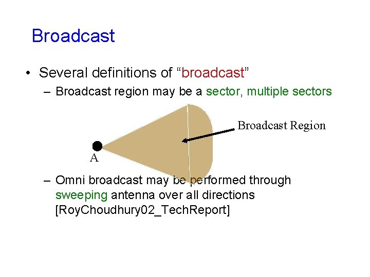
Broadcast • Several definitions of “broadcast” – Broadcast region may be a sector, multiple sectors Broadcast Region A – Omni broadcast may be performed through sweeping antenna over all directions [Roy. Choudhury 02_Tech. Report]
Do. A Detection • Signals received at each element combined with different weights at the receiver
Why DO ? • Antenna training required to beamform in appropriate direction – Training may take longer time than duration of pilot signal [Balanis 00_Tech. Report] – We assume long training delay • Also, quick Do. A detection does not make MMAC unnecessary
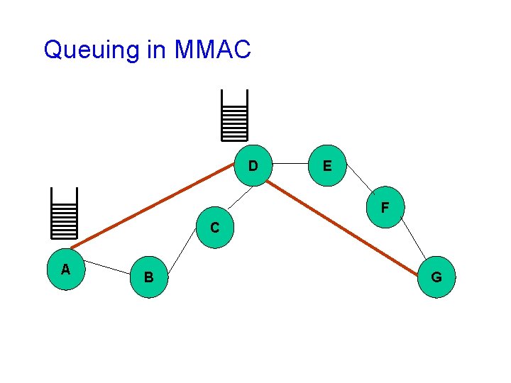
Queuing in MMAC D E F C A B G
Impact of Topology D A A E B B F C C Aggregate throughput 802. 11 – 1. 19 Mbps DMAC – 2. 7 Mbps Nodes arranged in linear configurations reduce spatial reuse for D-antennas Aggregate throughput 802. 11 – 1. 19 Mbps DMAC – 1. 42 Mbps
Organization • • • 802. 11 Basics Related Work Antenna Model MAC Routing Conclusion