ILC Final Focus 2014 02 26 ILC Final

 の概要 – TDR (Technical")


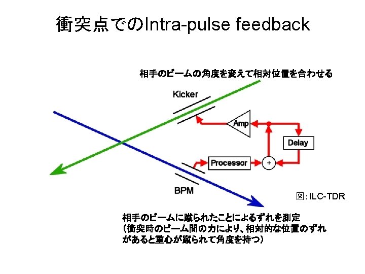
 h. kick Crab")
 ILC RDR parameter, by CAIN")


")


")

 at IP Extremely small vertical size (1: 80: 50000) length~300 mm")


 Chromatic, Geometrical Aberration correction Final Doublet")
 sqrt(exbx) hxs. E/E electron positron SF 6 755 0 0 SF 5")


 Model C ではルミノシティが10%程度減少する。")


")
")
 • Achievement of 37 nm beam size (Goal")
 at KEK Focal Point Extraction Line IP; ~40 nm beam")

 :位置と強さ 4 skew-sextupole corrector magnets:強さ Corrected coupling Linear")
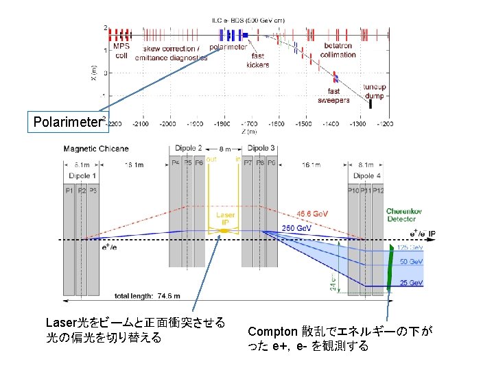
 Interference of two laser beams 電子ビームとの散乱で発生する ガンマ線の量を測定 q Example g 線強度")

 2013 winter")
 Fitted lines: Cannot be explained")
 – Demonstration of beam orbit stabilization")

")
- Slides: 139
ILC Final Focus を考える 訂正版 2014. 02. 26 久保浄
ILC Final Focus を考える • ILC BDS (Beam Delivery System) の概要 – TDR (Technical Design Report) から +a • • 衝突点でのビーム Final Focus Optics Final Focus のビーム調整 ATF での Final Focus Test
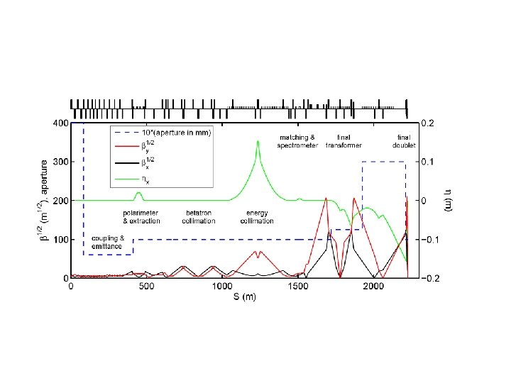
Beam Line Layout of BDS Final Focus
MPS coll: Machine Protection System Collimators Main Linac – BDS で aperture が小さくなる。
Skew correction / emittance diagnostics: 4 skew quadrupole magnets 4 laser wires (4 horizontal + 4 vertical beam size) Laser wire test at ATF extraction line, resolution 1 um
Laser wire monitor tested in ATF extraction beam line L. Nevay, et. al. , IPAC 2011 TUPC 158 Resolution ~ 1 micron or smaller L. Nevay, et. al. , ATF meeting 18 th May 2012 L. Corner, et. al, . ATF 2 project meeting 11 th Jan 2012
Tune-up and Emergency Extraction System Fast kicker: 問題が発生した時、以降のバンチをdumpに蹴り出す。 polarimeter, emittance diagnostics のBPMでenergy, orbit のずれを検出 以降のバンチを蹴りだす (下流に行ってしまうもの 1~2バンチ) バンチ間隔 550 ns Pulse magnet ビームパルス間(200 ms)でon-off Tuneup dump 上流のtuning 時などにもここのdumpにビームを捨てる Full power beam に対応 Beam sweeper
Collimation Betatron collimation 6 - 9 sx 40 - 60 sy half-gap ~1/0. 5 mm Energy collimation half gap 0. 5 - 1 mm hx 150 mm Betatron collimation Energy collimation
Collimation: Spoiler - Absorber Spoiler Absorber: 30 X 0 Spoiler: 0. 5 -1 X 0 ビームのコアが当たっても2 バンチまで耐えられる
Gap adjustable Spoiler TDR Copper ? Beryllium ? Beam Taper for reducing wakefield
Gap adjustable Spoiler B. D. Fell, et. al. , EPAC 08, Genoa, Italy, WEPP 168
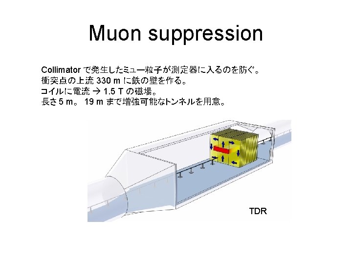
Muon suppression A. I. Drozhdin, et. al. , PAC 07, Albuquerque, THPMN 100
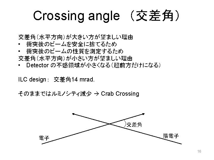
Crossing angle and crab crossing angle q (2 mrad in ILC) h. kick Crab crossing kick l. position kick 17
Luminosity vs. Crossing angle without crab (RDR param) ILC RDR parameter, by CAIN
Crab Cavity TDR
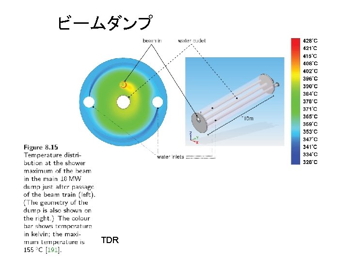
Extraction line IP Dump
Final Doublet + Extraction Quadrupole magnets
Final Quadrupole magnet + Sextupole magnet + Extraction Quadrupole magnets QD 0 : コイルを2つに分割 製作精度の向上(ID ~20 mm, Total L~ 3. 5 m) 低エネルギー運転でIPに近い方を強くできる TDR
Final Quadrupole magnet + Sextupole magnet + Extraction Quadrupole magnets TDR
TDR
Beam parameter at IP (Interaction Point)
TDR
TDR
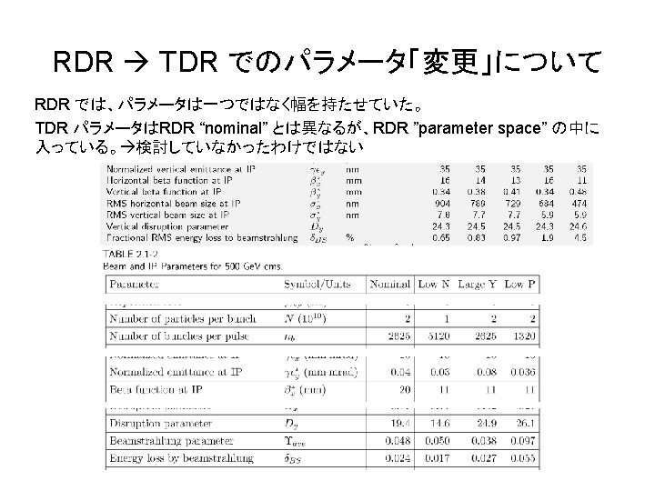
RDR (Reference Design Report)
Beam Parameters at IP for 250 Ge. V Ebeam • Vertical normalized emittance 35 nm (20 nm in DR) • Horizontal normalized emittance 10 um (5. 5 um in DR) • Betay* = 0. 48 mm (bunch length 0. 3 mm) – Hourglass effect, reasonable stability requirement, etc. – Far from Oide limit betay*~ 0. 015 mm • Betax* = 11 mm – Beam-beam • Beamstrahlung energy loss 4. 5% • Disruption parameter (vertical) 25
ILC beam (bunch) at IP Extremely small vertical size (1: 80: 50000) length~300 mm Particles/bunch 2 x 10¹⁰ hight~6 nm width~470 nm Beam direction 640 nm in RDR nominal
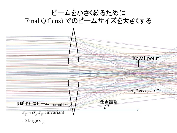
Hourglass effect - Focal depth of Beam Focusing Focal point Stronger focus smaller size at focal point shallow focal depth 33
Short focal depth Long focal depth Hourglass effect: Maximum luminosity: bunch length ~ focal depth. Need low emittance for high luminosity.
生出リミット Radiation in the focusing magnet Uncertain energy loss uncertain orbit downstream Quad magnet Stronger focus More uncertainty Larger beam size Normalized emittance 35 nm Optimum beta* ~ 0. 015 mm ILC design 0. 48 mm far from Oide-limit
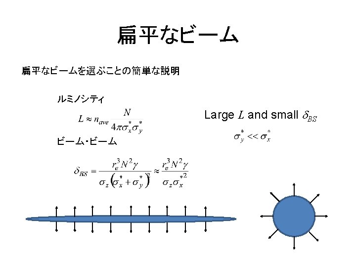
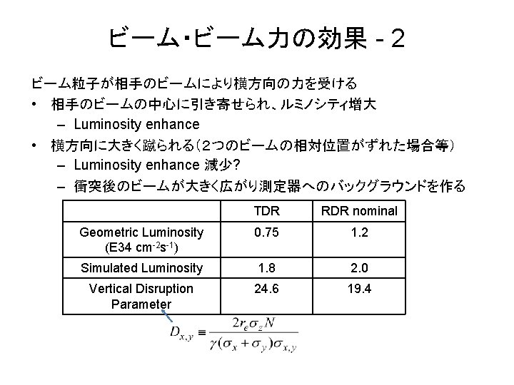
Beam-beam force の影響の例: Beamstrahlung ee+ • beamstrahlung makes energy spread in collisions. Affect quality of experimental data. • beamstrahlung parameter RDR (nominal): 2. 4% TDR: 4. 5 %
Expressions for luminosity hourglass effect beamstrarlung Luminosity can be a function of three parameters: number of colliding particles per time emittance and beamstrahlung energy loss
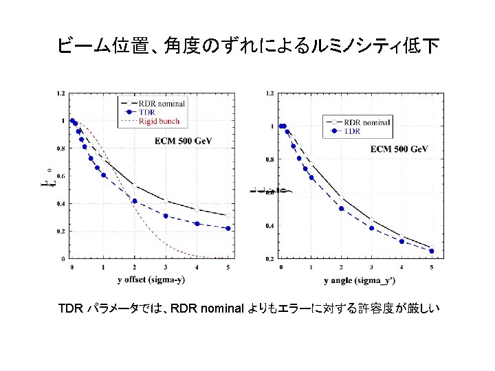
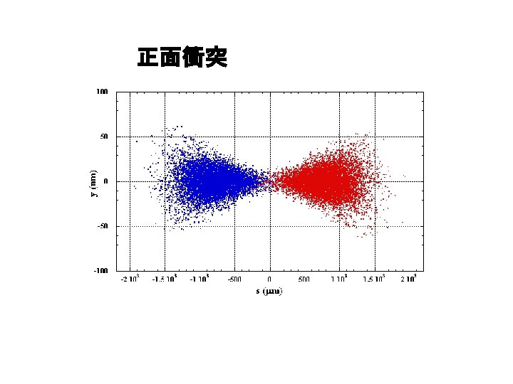
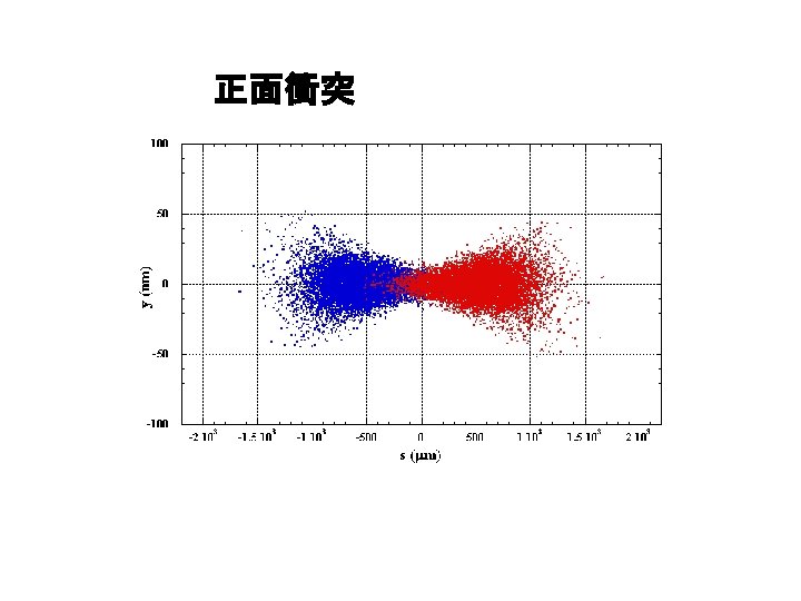
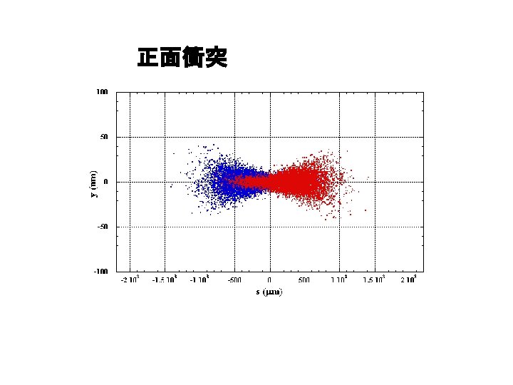
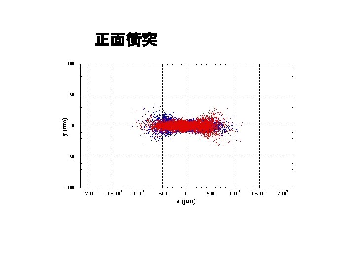
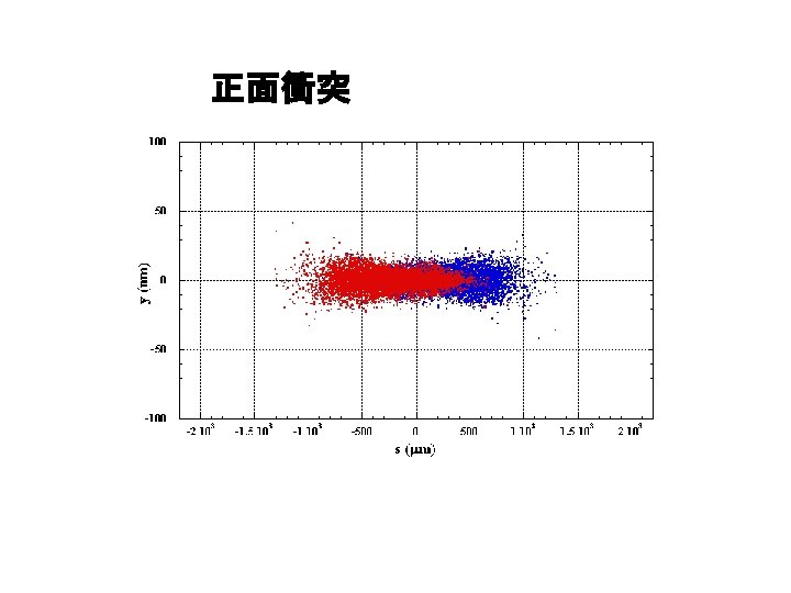
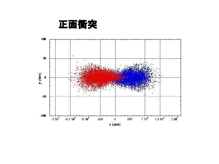
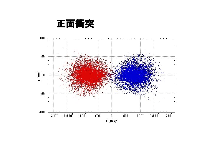
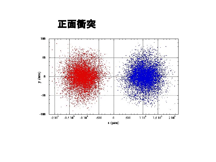
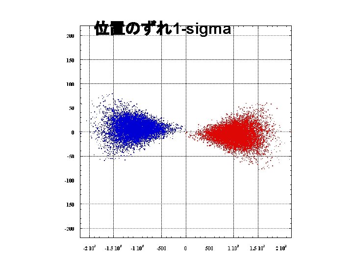
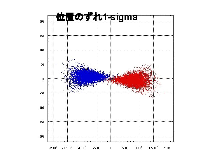
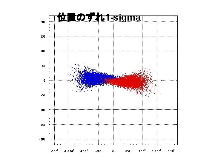
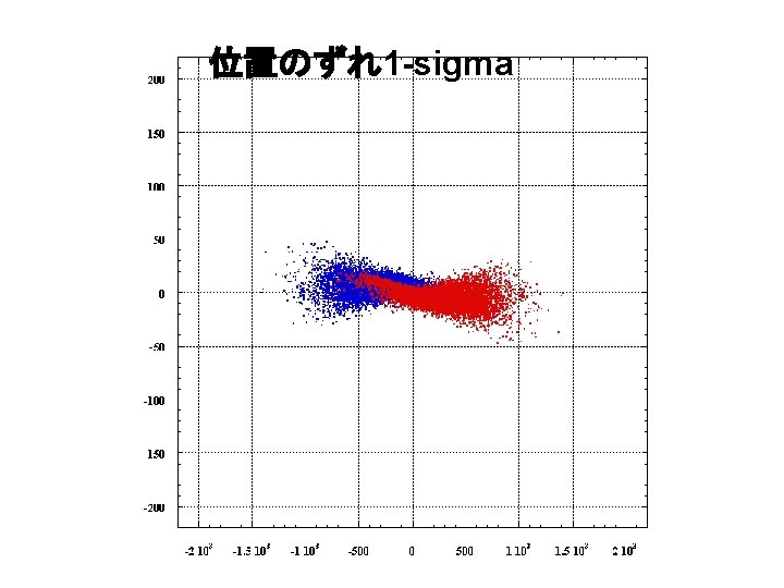
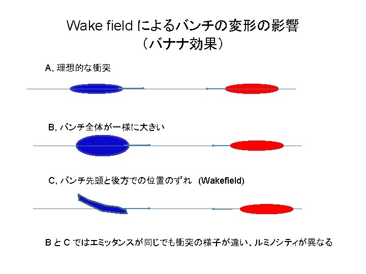
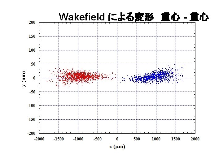
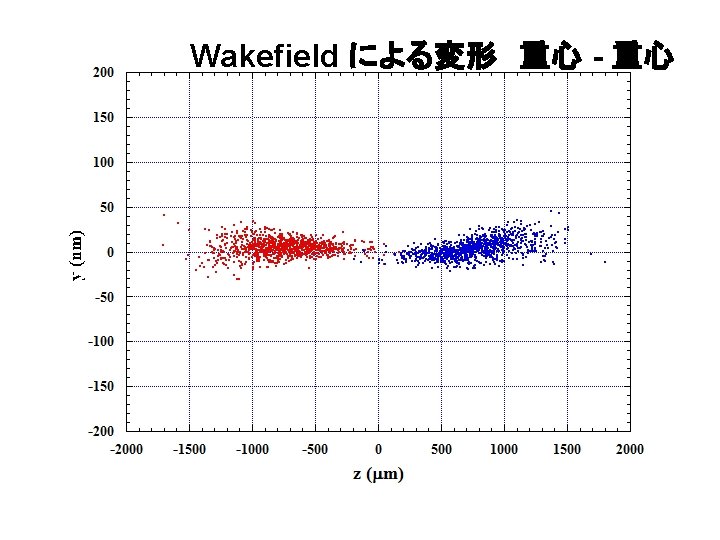
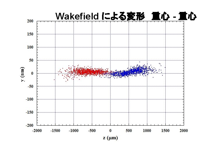
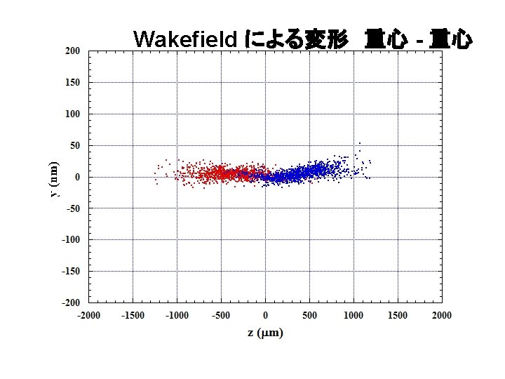
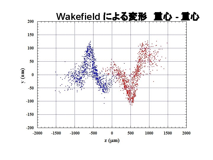
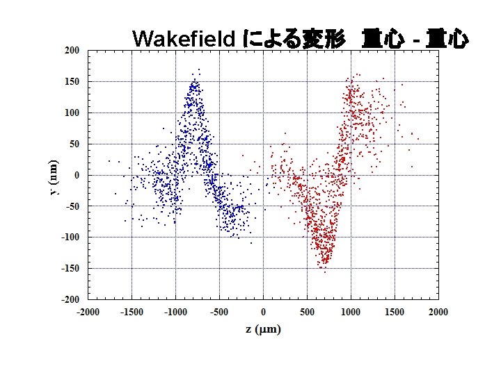
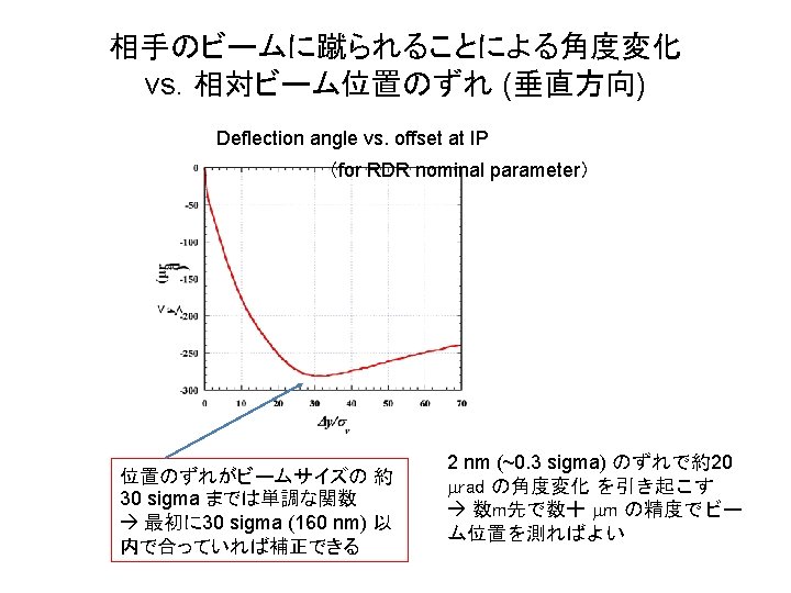
y offset y angle
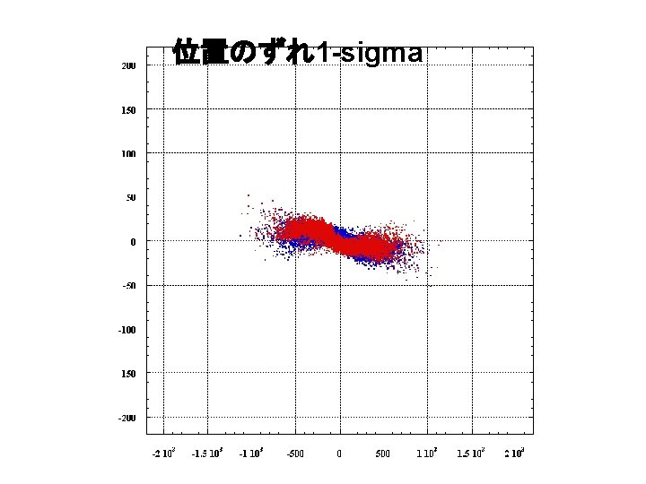
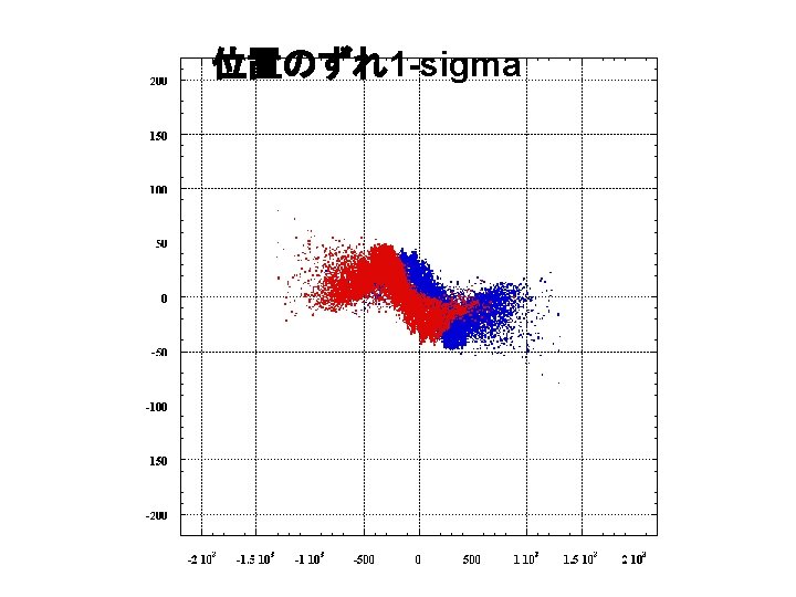
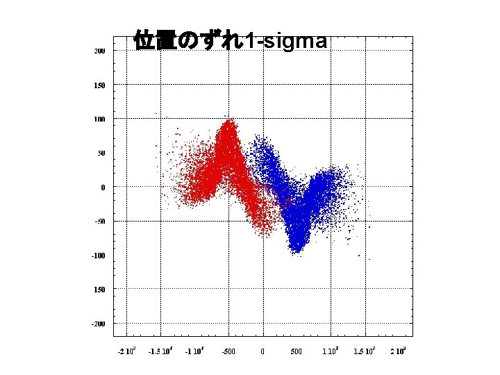
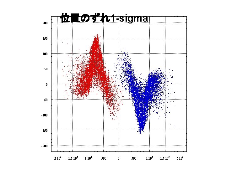
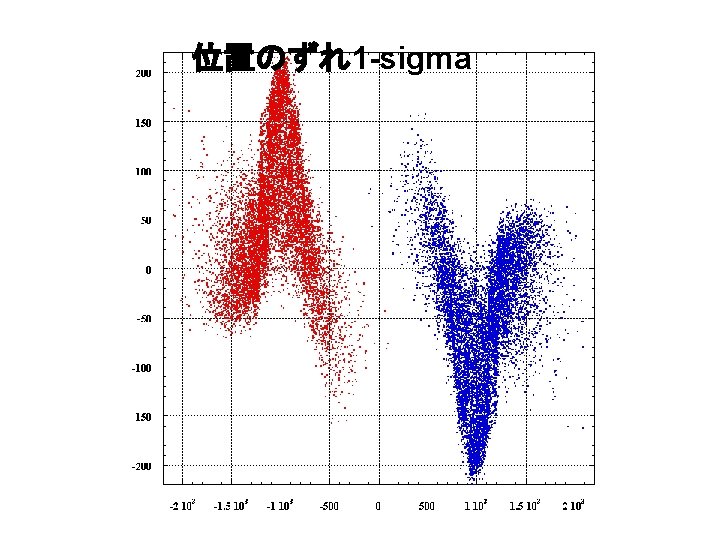
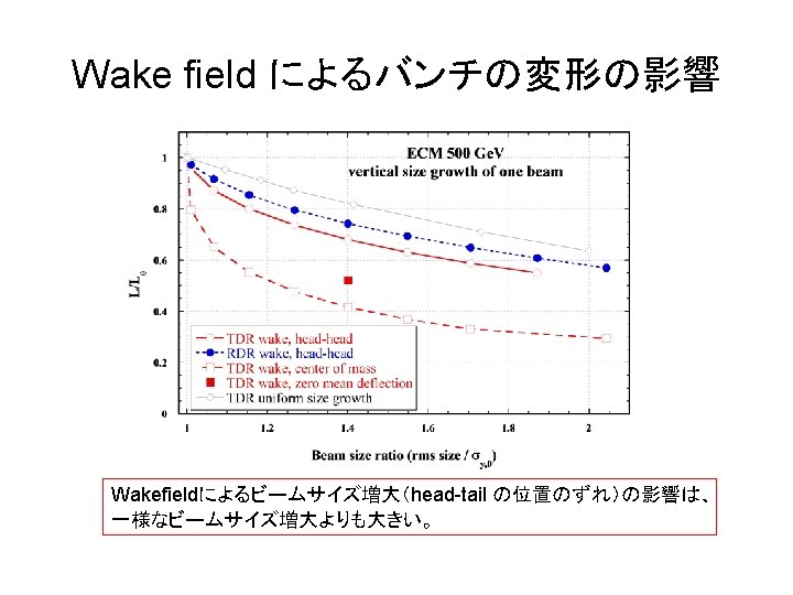
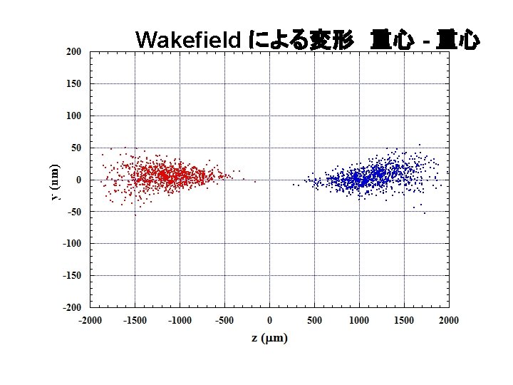
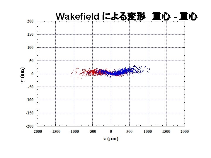
Wakefield による変形 head-head
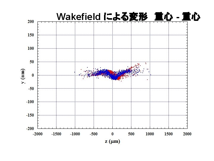
Wakefield による変形 head-head
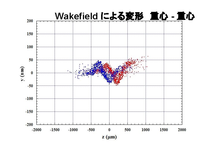
Wakefield による変形 head-head
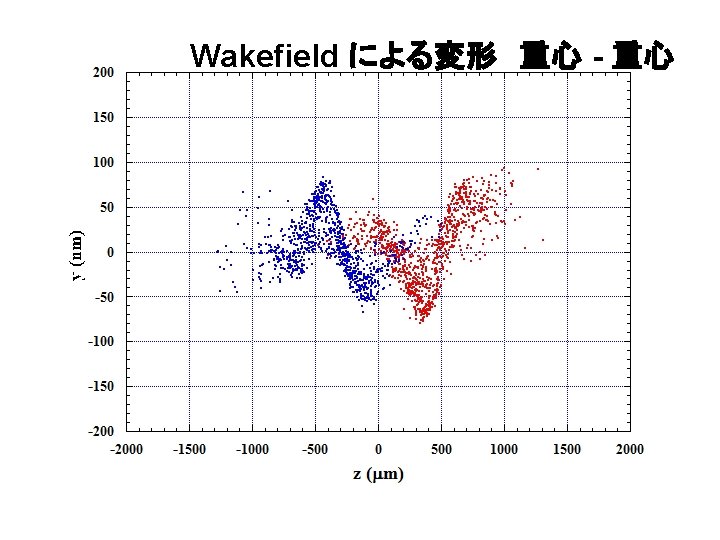
Wakefield による変形 head-head
Wakefield による変形 head-head
Wakefield による変形 head-head
Wakefield による変形 head-head
Wakefield による変形 head-head
Wakefield による変形 head-head
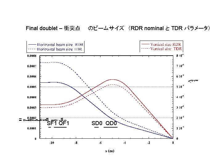
Final Focus Optics
Final doublet vertical horizontal
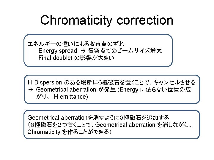
Final Focus Optics • Chromaticity Correction
Global correction Chromaticity のみを発生させる領域を別に作る 最終収束4極磁石 Chromatic aberration 衝突点 Chromaticity 1 Chromaticity 2 Mainly for x Mainly for y Chromaticity b 1/2 同じ強さの 6極磁場を対称に置くこ とでChromaticity を作り、 Geometrical aberration は消える hx 1 2 6極磁石 垂直、水平方向のchromaticity correction のため、2組必要
FF optics with global chromaticity correction Chromati city 1 Chromati city 2 P. Raimondi and A. Seryi, PRL Vol. 86 3779 (2001)
Local correction Final Q の隣に6極磁石を置き、Chromaticity を補正する。 発生したGeometrical aberration等は上流で補正 6極磁石 Geometric Correction 6極磁石 Chromatic Correction 最終収束4極磁石 Geometric Aberration 発生 Chromatic aberration 発生 衝突点 ~np Chromaticity Cancel Horizontal Dispersion
FF optics with local chromaticity correction (ILC TDR) Chromatic, Geometrical Aberration correction Final Doublet + Chromaticity correction IP
6極磁石中心でのエミッタンス、ディスパージョンの ビームサイズへの寄与 (mm) sqrt(exbx) hxs. E/E electron positron SF 6 755 0 0 SF 5 755 85 46 SD 4 482 54 29 SF 1 718 203 109 SD 0 383 108 58 sqrt(eyby) 30 30 50 30 47
各部のChromaticityへの寄与 Quadrupole magnets Sextupole magnets QD 0 の寄与を SD 0 でほぼ打ち消しているが、 完全に「Local」というわけではない
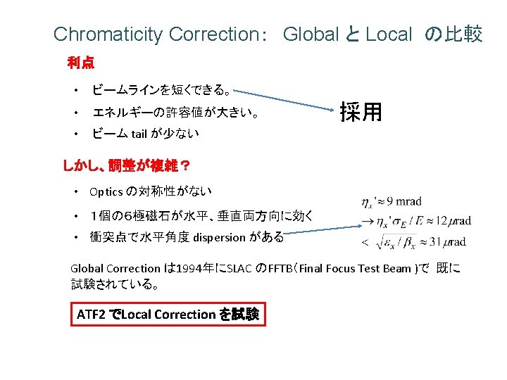
Local Correction Global Correction の比較 Local Correction の方が Energy Acceptance が大きい。 2001 Report on the Next Linear Collider: A report submitted to Snowmass '01 http: //www-project. slac. stanford. edu/lc/wkshp/snowmass 2001/ Local correction: beam halo が小さい Final Q 入り口での粒子の分布 P. Raimondi and A. Seryi, PRL VOLUME 86, NUMBER 17, p 3779 設計通りにできれば、Local Correction の方が性能が良い。
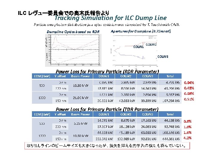
Final Focus Line で発生するEnergy Spread は Chromaticity Correction が効かない Dispersion を作り始める Bend の中とその下流で発生するenergy 変化 Position = Dispersion x Energy deviation という関係が崩れる Energy change << 1/ Chromaticity of Final Q ~ 1/10000 でなければならない。 Roughly estimated energy spread induced by each effect Space charge 7 E-11 Resistive wall wake 1. 1 E-5 Incoherent SR 1. 5 E-5 Coherent SR < 1. 3. E-6 Crab cavities wake 1 E-6 Cavity BPM wake 1. 4 E-5** copper coated stainless steel beam pipe Weak bending magnets ~ 0. 04 T **ATF 2 cavity BPM design assumed. Can be reduced by careful design.
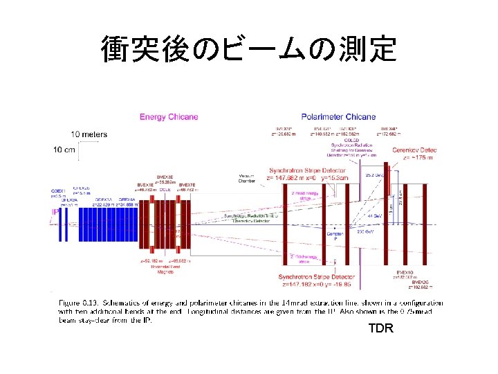
Y. Nosochkov, et. al. , “ILC EXTRACTION LINE FOR 14 MRAD CROSSING ANGLE” SLAC-PUB-11591 Conclusion: “. . . The tracking simulations showed that the losses of primary electrons and BS photons are acceptable in the considered nominal and high-L options except the 1 Te. V CM high-L option (c 25) which should be excluded from consideration. . ” ~RDR nominal ~TDR
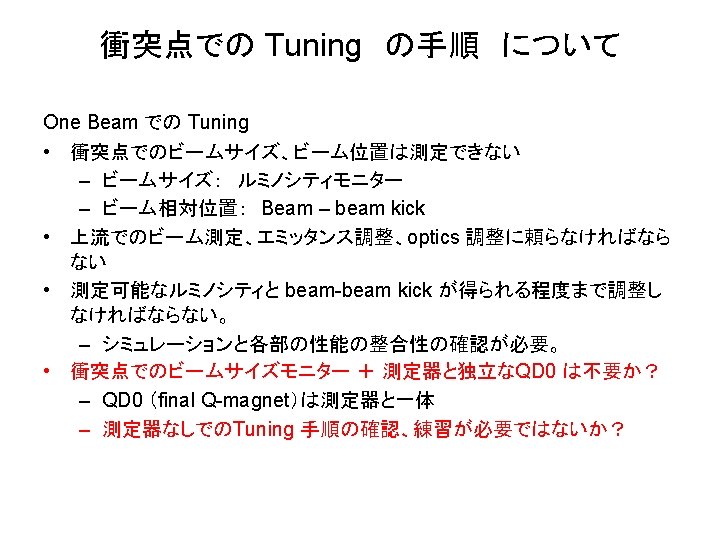
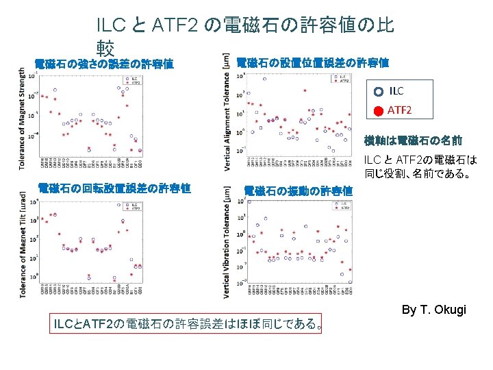
衝突点でのビームサイズ調整 • Beam Based Alignment • ほとんどの磁石は精密な可動台の上に置かれる • Optics 補正、Dispersion 補正 • 上流のビームサイズモニター 初期の調整手順について後述 • BPM • ビームサイズ調整ノブ 垂直ビームサイズ調整ノブ: sextupole magnets (on movers) の位置と強さ Corrected coupling Linear knob (線形オプティク ス調整) Horizontal move of sextupole magnets Vertical move of sextupole magnets yy’ (Focal Position) Ey (Dispersion) x’y Non-linear knob Strength change of sextupole magnets x’yy’ Eyy’
Ground motion model A, B, C, K を使ったシミュレーション例 (TDR PartI p 162) Model C ではルミノシティが10%程度減少する。 ほとんどの影響はBDSで発生する。 TDR Ground motion model A, B, C: International Linear Collider Technical Review Committee, Second Report, SLAC-R-606, 2003.
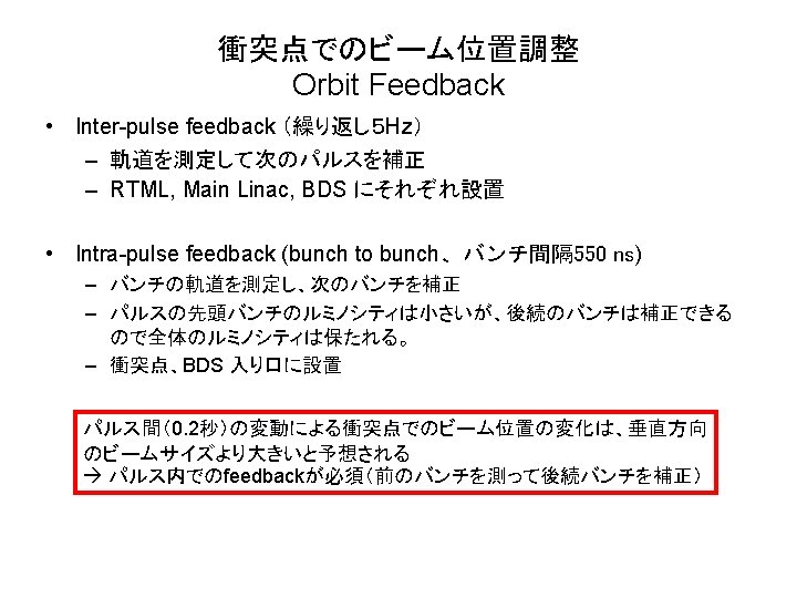
Luminosity of head bunch is small Orbit feed back recovers luminosity Scan angle etc. searching higher luminosity
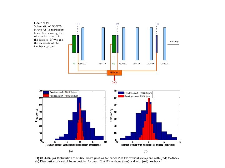
Beam Stabilization at ATF-EXT ー Intra-train Fast Feedbackー FONT feedback EXT-FONT by stripline BPM, result 2014/Jan - latency ~133 ns ILC bunch spacing 550 ns (nominal) 550/2 ns (upgrade) Feed backの速さ は問題ない Slide from Terunuma FONT group, slide from Terunuma
QD 0 + SD 0 + QDEX 1 beam “push pull” beam
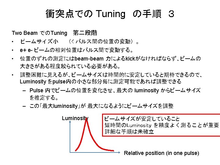
Luminosity Max. Luminosity Beam position scan Beam size knob change Max. Luminosity Beam size knob
Fast Luminosity monitor The ILC luminosity can be measured with a precision of 10− 3 or better by measuring the Bhabha rate in the polar-angle region from 30– 90 mrad. Two detectors are located just in front of the final doublets. The Lumi. Cal covers the range from 30– 90 mrad and the Beam. Cal covers the range from 5– 30 mrad. At 500 Ge. V centre-of-mass energy, the expected rate in the Lumi. Cal region is 10 Bhabhas per bunch train, which is too low to permit its use as an intra-train diagnostic for tuning and feedback. At smaller polar angles of 5 -30 mrad the rate or energy deposition of beamstrahlung e+e− pairs can be measured and provides a fast luminosity diagnostic. The expected rate in this region is 15 000 pairs (and 50 Te. V energy deposition) per bunch crossing. Furthermore, the spatial distributions of pairs in this region can be used to determine beam-collision parameters such as transverse sizes and bunch lengths.
Si. D forward region (from TDR)
ILD forward region (from TDR)
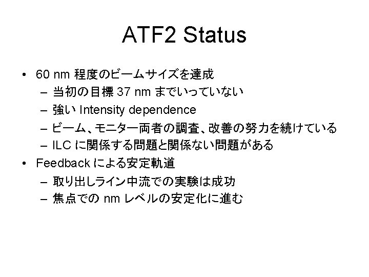
ATF での Final Focus Test (ATF 2) • Achievement of 37 nm beam size (Goal 1) – Demonstration of a compact final focus system based on local chromaticity correction • Control of beam position (Goal 2) – Demonstration of beam orbit stabilization with nanometer precision at the IP • Establishment of beam jitter controlling techniques at the nano-meter level with an ILC-like beam
Accelerator Test Facility (ATF) at KEK Focal Point Extraction Line IP; ~40 nm beam Final Focus Test Line ATF Damping Ring (140 m) Photo-cathode RF Gun ATF Linac (1. 3 Ge. V)
ILC FF ATF 2 FF
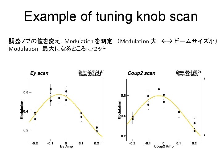
ビーム調整: 垂直ビームサイズ調整ノブ 5 sextupole magnets (on movers) :位置と強さ 4 skew-sextupole corrector magnets:強さ Corrected coupling Linear knob (線形オプティク ス調整) Horizontal move of sextupole magnets Vertical move of sextupole magnets yy’ (Focal Position) Ey (Dispersion) x’y Non-linear knob Strength change of sextupole magnets x’yy’ Strength change of skew sextupole magnets xxy Eyy’ Exy EEy yy’y’
焦点でのビームサイズ測定 Shintake-monitor, (IP-BSM) Interference of two laser beams 電子ビームとの散乱で発生する ガンマ線の量を測定 q Example g 線強度 Fringe scan Fringe phase Scan interference fringe position. Measure modulation.
Status of Goal 1 History of measured beam size Goal Modulation With 30 deg. mode With 2~8 deg. mode Modulation With 174 deg. mode No significant improvement in the period from autumn 2013 to Jan. 2014, which was mostly for IPBPM commissioning.
December 2012: first observation of fringe with 174 deg mode (<70 nm) 2013 winter - spring: Establish tuning procedure, better result (60 -65 nm) (Only with low bunch intensity) Results of 10 consecutive measurements after tuning 2012 Dec. 2013 March 2012/12/21 These histograms do not consider systematic error of the beam size monitor.
Intensity Dependence example Different in different weeks. (? ) Fitted lines: Cannot be explained by intrabeam scattering in DR, etc. .
• Control of beam position (Goal 2) – Demonstration of beam orbit stabilization with nanometer precision at the IP • Establishment of beam jitter controlling techniques at the nano-meter level with an ILC-like beam
Beam Stabilization at ATF-EXT ー Intra-train Fast Feedbackー FONT feedback EXT-FONT by stripline BPM, result 2014/Jan IP-FONT - latency ~133 ns by IP Cavity BPM expected (from results in EXT) FB OFF: jitter 14. 7 nm FB ON: jitter 2. 6 nm ? Slide from Terunuma FONT group, slide from Terunuma
IP nm beam position stabilize system IP-FONT – Monitor: Cavity BPM(designed resolution 2 nm) – Stlipline BPMs (resolution 0. 4 um) were used for the beam test in EXT Slide from Terunuma 137