EEE 161 IMPEDANCE MATCHING Recall What do we


 •")
 •")


 Cont.")
")


")


 WTG Read")


 • Using Smith Chart design two transmission line impedance matching")


- Slides: 121
EEE 161 IMPEDANCE MATCHING
Recall • What do we know about Power?
Objective • Students will be able to – explain why is the impedance matching needed – How real power changes from the input to the output of a lossless transmission line – What is the requirement for maximum available power from the generator? – What is the requirement for the minimum reflected power from the load?
Why do we look at power transfer at RF? • At lower frequencies we look at voltage gain or current gain • At Radio Frequencies (RF) we look at the power transfer • At low frequencies the voltage at one end of a cable is the same as the voltage at the other side of the cable • At RF the voltage at the input of the cable is not the same as the voltage at the output, BUT: the delivered power at the input port is the same as the power delivered to the load (no power is dissipated in reactive elements)
Wave propagation on a TL
Impedance matching • We need to maximize power transfer between source and the load • Maximum power transfer occurs when the impedance of the load and the generator are complex conjugate of each other. • This maximizes V
Instantaneous Power Flow
Average Power
Conjugate match maximizes ZL=Zo Minimizes reflection
Incident, Reflected and Delivered Power • Seemingly, we have two requirements: • 1) • 2) For maximum power transfer To minimize reflected power What is the input impedance Zin=? if ZL=Zo? Look at the Smith Chart. Where is ZL (normalized)?
Incident, Reflected and Absorbed Power • Seemingly, we have two requirements: • 1) • 2) Maximizes Minimizes Available power from the generator • When Zl=Zo, and Zg=Zo, then we have the best of both worlds!
Graded Quiz IM#1 A transmitter operated at 20 MHz, Vg=100 V with 50Ω internal impedance is connected to an antenna load through 6. 33 m of the line. The line is a lossless 50Ω, β=0. 595 rad/m. The antenna impedance at 20 MHz measures ZL=36+j 20 Ω. a) What is the electrical length of the line? (length=0. 6 λ ) b) How much power is delivered to the line? Hint: Find the input impedance, then Pav, in=1/2 Re{V (I )*}=1/2 Re{Z I (I )*}=1/2 R *|I |^2 c) What is the time-average power absorbed by Z ? P =1/2 R * |I |^2 d) If Z is matched to 50 Ohm line, what is the input impedance of the line, and how much average power is delivered to the line and load? in in in l l l in l l
At the load z=0
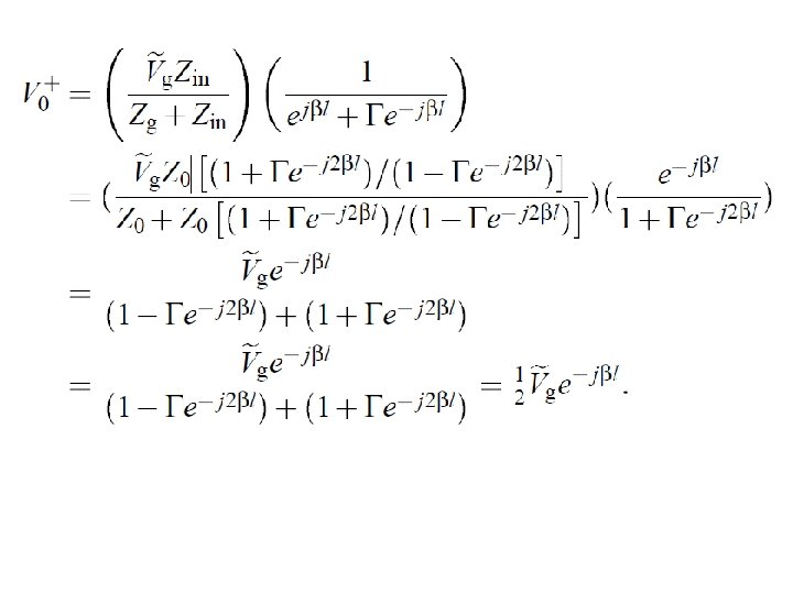
Answers Note that the “real” power at the load and the “real” power at the generator are the same.
(cont. ) Cont.
(cont. )
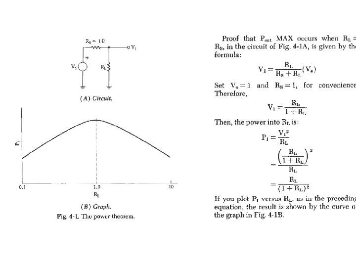
Why are we doing impedance matching? MAXIMUM POWER TRANSFER
SIMPLEST IMPEDANCE MATCHING CASE
Objective • Students will be able to – Design a lumped element impedance matching network for the load impedance Z=1+j. X or Z=1 -j. X (removing reactance only)
Guided Exercise • The load impedance is given ZL=50+j 50. Find the impedance matching network to match this impedance to 50 Ohm generator.
First Normalize the Impedance • 50 Ohm Generator (or transmission line)
Which circle would you use to go to the center “Game” move the Zl to the center of the Smith Chart using only circles that are centered on the x-axis. Why? Because we only want to add reactances or susceptances to ZL.
Independent Exercise • Find the impedance matching network to match impedance ZL=50 -j 100 Ω to 50Ω generator. • Describe how is the load impedance transformed using Smith Chart • Sketch the circuit: load impedance, the impedance matching circuit and the generator
Motivation • What if we have to match a dipole antenna to 50 Ω line? • How is this impedance different than the previous one?
Motivation • This impedance does not have the real part equal to 50 Ω. • We have to transform real and imaginary parts!
MIXED IMPEDANCE MATCHING NETWORK
Objective • Students will be able to – Design a mixed transmission line and lumped element impedance matching network for any load impedance
Mixed impedance matching network • Add a line to the load so that the – impedance at the input of the line is Zin=1+j. X or 1 -j. X (make the resistance = 50 Ohms) – OR admittance at the input of the line is Yin=1+j. B or 1 -j. B (make the conductance 1/50 Si. ) • Then add a lumped element in series or parallel to remove the reactive part of the impedance
Guided Example • Using Smith Chart Design TWO different mixed impedance matching networks to match ZL=25+j 50 Ω impedance to a 50 -Ω line.
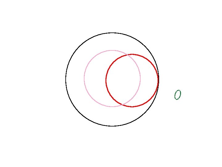
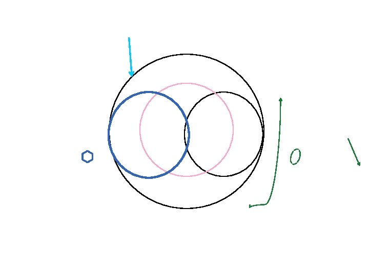
Where all the points on the Smith Chart where the input impedance can be =1 or input admittance can be =1 Where all the points on the Smith Chart where THIS TL can have real part of input impedance or admittance =1. How long should the line be so that the real part of the input impedance is equal to 50 (norm. 1)?
Now add the reactance in series or parallel to cancel the reactive impedance at the input of the transmission line!
Now add the reactance in series or parallel to cancel the reactive impedance at the input of the transmission line!
What are we trying to do?
Guided Example • Using Smith Chart Design TWO different mixed impedance matching networks to match ZL=25+j 50 Ω impedance to a 50 -Ω line.
Solution 1
Solution 1 on Smith Chart
Solution 1 on Smith Chart
Solution 1 on Smith Chart
Solution 1 on Smith Chart Read the reference position (0. 135 λ) WTG Read the input impedance position (0. 425 λ) WTG
Solution 2
Graded Quiz IM#2 • Using Smith Chart design two mixed impedance matching networks to match a half -wave dipole with input impedance ZL=74+j 42. 5 Ω to a 50 -Ω line. • One should consider R=1 and the other G=1 Jargon alert: I say “input impedance of the dipole”, because I am looking into the dipole, and its impedance is the load impedance to the transmission line.
TRANSMISSION LINE IMPEDANCE MATCHING CIRCUIT
Transmission Line Impedance Matching Circuit • Add a line to the load so that the – input impedance of the line is 1+j. X or 1 -j. X – OR input admittance of the line is 1+j. B or 1 -j. B • Add a stub to remove reactive impedance j. X or JB
What is a stub? • Stubs are transmission lines with short circuit or open circuit loads • Input impedance will be reactive
Find the input impedance of a open line l=0. 125λ
Find the input impedance of What a will happen if the line is a open line l=0. 125λ little shorter/longer, longer than 0. 25
General statement about input impedance?
Guided/Independent Exercise (IM#3 prep) • Using Smith Chart design two transmission line impedance matching networks to match a half-wave dipole with input impedance ZL=74+j 42. 5 Ohms to a 50 -Ohm line. • Hint: Just replace lumped elements with stubs
How do we design the stub to look like inductor of Z=j 0. 8?
Graded Quiz IM#3 • Use the solution of IM#2 to make two purely transmission line impedance matching circuits. { Hint: In your IM#2 replace the lumped element with a shorted or open stub. }
• Why only transmission lines • Pictures of lumped elements
LUMPED ELEMENT IMPEDANCE MATCHING CIRCUIT
Objective • Students will be able to – Design a lumped element impedance matching network for any load impedance
Lumped Element matching network • Add an element in series or parallel to ZL so that the – impedance at the input of the line is Zin=1+j. X or 1 -j. X (make the resistance = 50 Ohms) – OR admittance at the input of the line is Yin=1+j. B or 1 -j. B (make the conductance 1/50 Si. • Then add a lumped element in series or parallel to remove the reactive part of the impedance
Guided Example • Using Smith Chart Design TWO different lumped element impedance matching networks to match 100+j 200 impedance to a 50 Ohm line.
First we normalize ZL
Solution 1
Solution 2
Solution 2
Solution 2
Solution 2
Graded Quiz IM#4 • Using Smith Chart design four lumped element matching networks to match an antenna with input impedance ZL=40+j 100 Ohms to a 100 Ohm line. • Hint: Outline the paths on the Smith Chart first!
Assignments • Homework 5 needs to be completed soon