TOPIC 4 THREE PHASE CIRCUIT SINGLE PHASE TWO


 surrounded by a")


 –")
 –")


 is the current in each")


 LINE VOLTAGE (VL)")


 LINE CURRENTS (IL)")


, reactive power (Q), and complex power (S) at")


- Slides: 98
TOPIC 4: THREE PHASE CIRCUIT
SINGLE PHASE TWO WIRE
SINGLE PHASE SYSTEM • A generator connected through a pair of wire to a load – Single Phase Two Wire. • Vp is the magnitude of the source voltage, and is the phase.
SINGLE PHASE THREE WIRE
SINGLE PHASE SYSTEM • Most common in practice: two identical sources connected to two loads by two outer wires and the neutral: Single Phase Three Wire. • Terminal voltages have same magnitude and the same phase.
POLYPHASE SYSTEM • Circuit or system in which AC sources operate at the same frequency but different phases are known as polyphase.
TWO PHASE SYSTEM THREE WIRE
POLYPHASE SYSTEM • Two Phase System: – A generator consists of two coils placed perpendicular to each other – The voltage generated by one lags the other by 90.
POLYPHASE SYSTEM • Three Phase System: – A generator consists of three coils placed 120 apart. – The voltage generated are equal in magnitude but, out of phase by 120. • Three phase is the most economical polyphase system.
THREE PHASE FOUR WIRE
IMPORTANCE OF THREE PHASE SYSTEM • All electric power is generated and distributed in three phase. – One phase, two phase, or more than three phase input can be taken from three phase system rather than generated independently. – Melting purposes need 48 phases supply.
IMPORTANCE OF THREE PHASE SYSTEM • Uniform power transmission and less vibration of three phase machines. – The instantaneous power in a 3 system can be constant (not pulsating). – High power motors prefer a steady torque especially one created by a rotating magnetic field.
IMPORTANCE OF THREE PHASE SYSTEM • Three phase system is more economical than the single phase. – The amount of wire required for a three phase system is less than required for an equivalent single phase system. – Conductor: Copper, Aluminum, etc
THREE PHASE GENERATION
FARADAYS LAW • Three things must be present in order to produce electrical current: a) Magnetic field b) Conductor c) Relative motion • • Conductor cuts lines of magnetic flux, a voltage is induced in the conductor Direction and Speed are important
GENERATING A SINGLE PHASE S N Motion is parallel to the flux. No voltage is induced.
GENERATING A SINGLE PHASE S x N Motion is 45 to flux. Induced voltage is 0. 707 of maximum.
GENERATING A SINGLE PHASE S x N Motion is perpendicular to flux. Induced voltage is maximum.
GENERATING A SINGLE PHASE S x N Motion is 45 to flux. Induced voltage is 0. 707 of maximum.
GENERATING A SINGLE PHASE S N Motion is parallel to flux. No voltage is induced.
GENERATING A SINGLE PHASE S x N Notice current in the conductor has reversed. Motion is 45 to flux. Induced voltage is 0. 707 of maximum.
GENERATING A SINGLE PHASE S x N Motion is perpendicular to flux. Induced voltage is maximum.
GENERATING A SINGLE PHASE S x N Motion is 45 to flux. Induced voltage is 0. 707 of maximum.
GENERATING A SINGLE PHASE S N Motion is parallel to flux. No voltage is induced. Ready to produce another cycle.
THREE PHASE GENERATOR
GENERATOR WORK • The generator consists of a rotating magnet (rotor) surrounded by a stationary winding (stator). • Three separate windings or coils with terminals a-a’, b-b’, and c-c’ are physically placed 120 apart around the stator.
• As the rotor rotates, its magnetic field cuts the flux from the three coils and induces voltages in the coils. • The induced voltage have equal magnitude but of phase by 120.
GENERATION OF THREE-PHASE AC S x x N
THREE-PHASE WAVEFORM Phase 1 120 Phase 2 Phase 3 120 240 Phase 2 lags phase 1 by 120. Phase 3 lags phase 1 by 240. Phase 2 leads phase 3 by 120. Phase 1 lags phase 3 by 120.
GENERATION OF 3 VOLTAGES Phase 1 Phase 2 Phase 3 The algebraic sum of the instantaneous voltages of the three phases equals zero. Phase 1 is ready to go positive. Phase 2 is going more negative. Phase 3 is going less positive. S x x N
THREE PHASE QUANTITIES
BALANCED 3 VOLTAGES • Balanced three phase voltages: – same magnitude (VM ) – 120 phase shift
BALANCED 3 CURRENTS • Balanced three phase currents: – same magnitude (IM ) – 120 phase shift
PHASE SEQUENCE POSITIVE SEQUENCE NEGATIVE SEQUENCE
PHASE SEQUENCE
EXAMPLE • Determine the phase sequence of the set voltages: Ans: Negative Sequence
BALANCED VOLTAGE AND LOAD • Balanced Phase Voltage: all phase voltages are equal in magnitude and are out of phase with each other by 120. • Balanced Load: the phase impedances are equal in magnitude and in phase.
THREE PHASE CIRCUIT • POWER – The instantaneous power is constant
THREE PHASE CIRCUIT • Three Phase Power,
THREE PHASE QUANTITIES QUANTITY SYMBOL Phase current I Line current IL Phase voltage V Line voltage VL
PHASE VOLTAGES and LINE VOLTAGES • Phase voltage is measured between the neutral and any line: line to neutral voltage • Line voltage is measured between any two of the three lines: line to line voltage.
PHASE CURRENTS and LINE CURRENTS • Line current (IL) is the current in each line of the source or load. • Phase current (I ) is the current in each phase of the source or load.
THREE PHASE CONNECTION
SOURCE-LOAD CONNECTION SOURCE LOAD CONNECTION Wye Y-Y Wye Delta Y- Delta Wye -Y
SOURCE-LOAD CONNECTION • Common connection of source: WYE – Delta connected sources: the circulating current may result in the delta mesh if the three phase voltages are slightly unbalanced. • Common connection of load: DELTA – Wye connected load: neutral line may not be accessible, load can not be added or removed easily.
WYE CONNECTION
WYE CONNECTED GENERATOR
WYE CONNECTED LOAD OR
BALANCED Y-Y CONNECTION
PHASE CURRENTS AND LINE CURRENTS • In Y-Y system:
PHASE VOLTAGES, V • Phase voltage is measured between the neutral and any line: line to neutral voltage Van Vbn Vcn
PHASE VOLTAGES, V
LINE VOLTAGES, VL • Line voltage is measured between any two of the three lines: line to line voltage. Vab Vca Vbc
LINE VOLTAGES, VL
PHASE VOLTAGE (V ) LINE VOLTAGE (VL)
PHASE DIAGRAM OF VL AND V
PROPERTIES OF PHASE VOLTAGE • All phase voltages have the same magnitude, V = l. Vanl = l. Vbnl = l. Vcnl • Out of phase with each other by 120
PROPERTIES OF LINE VOLTAGE • All line voltages have the same magnitude, VL = l. Vabl = l. Vbcl = l. Vcal • Out of phase with each other by 120
RELATIONSHIP BETWEEN V and VL 1. Magnitude 2. Phase - VL LEAD their corresponding V by 30
EXAMPLE • Calculate the line currents
Single Phase Equivalent Circuit • Phase ‘a’ equivalent circuit 5 -j 2
DELTA CONNECTION
DELTA CONNECTED SOURCES
DELTA CONNECTED LOAD OR
BALANCED - CONNECTION
PHASE VOLTAGE AND LINE VOLTAGE • In - system, line voltages equal to phase voltages:
PHASE CURRENTS, I • Line voltages are equal to the voltages across the load impedances.
PHASE CURRENTS, I • The phase currents are obtained:
LINE CURRENTS, IL • The line currents are obtained from the phase currents by applying KCL at nodes A, B, and C.
LINE CURRENTS, IL
PHASE CURRENTS (I ) LINE CURRENTS (IL)
PHASE DIAGRAM OF IL AND I
PROPERTIES OF PHASE CURRENT • All phase currents have the same magnitude, • Out of phase with each other by 120
PROPERTIES OF LINE CURRENT • All line currents have the same magnitude, • Out of phase with each other by 120
RELATIONSHIP BETWEEN I and IL 1. Magnitude 2. Phase - VL LAG their corresponding V by 30
EXAMPLE A balanced delta connected load having an impedance 20 -j 15 is connected to a delta connected, positive sequence generator having Vab = 330 0 V. Calculate the phase currents of the load and the line currents.
Given Quantities
Phase Currents
Line Currents
BALANCED WYE-DELTA SYSTEM
EXAMPLE A balanced positive sequence Yconnected source with Van=100 10 V is connected to a -connected balanced load (8+j 4) per phase. Calculate the phase and line currents.
Given Quantities • Balanced WYE source – Van= 100 10 V • Balanced DELTA load – Z = 8+j 4
Phase Currents VAB= voltage across Z = Vab= source line voltage
Phase Currents
Line Currents
DELTA TO WYE CONVERSION
THREE PHASE POWER MEASUREMENT
FOUR WIRE SYSTEM • Each phase measured separately:
THREE PHASE THREE WIRE SYSTEM The three phase power is the sum of the two wattmeters reading
EXAMPLE Determine the total power (P), reactive power (Q), and complex power (S) at the source and at the load
Single Phase Equivalent Circuit • Phase ‘a’ equivalent circuit 5 -j 2
Known Quantities • V =Van = 110 0 V • ZY = 10+j 8 • Zline =5 -j 2
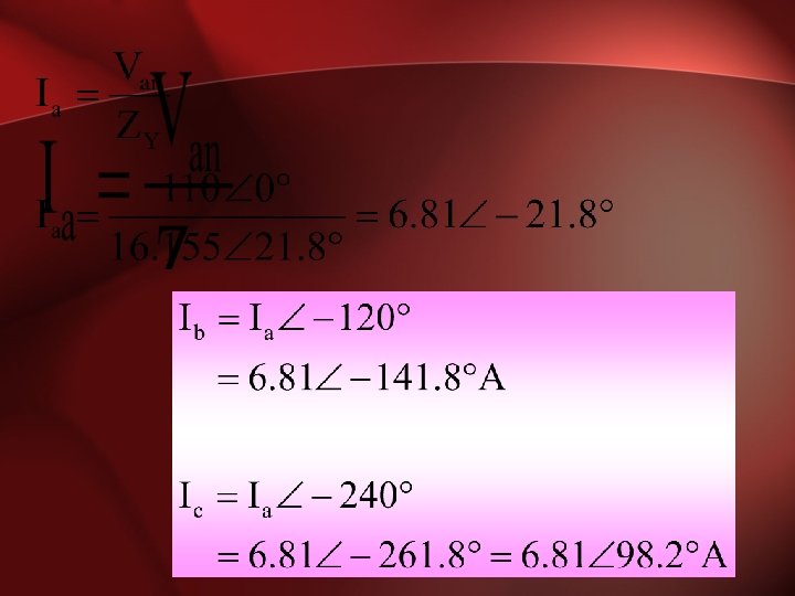
Line/Phase Currents
Source & Load Power
EXAMPLE A three phase motor can be regarded as a balanced Y-load. A three phase motor draws 5. 6 k. W when the line voltage is 220 V and the line current is 18. 2 A. Determine the power factor of the motor
Known Quantities • PLoad =5600 W • VL = 220 V • IL = 18. 2 A
Power factor • Power factor = cos |S| Q P