
DREAM IDEA PLAN IMPLEMENTATION Present to Amirkabir University

DREAM IDEA PLAN IMPLEMENTATION

Present to: Amirkabir University of Technology (Tehran Polytechnic) & Semnan University Dr. Kourosh Kiani 2 Email: kkiani 2004@yahoo. com Email: Kourosh. kiani@aut. ac. ir Web: aut. ac. com

i(t) R 2 a + _ R 1 c d b R 3 R 4 v(t) + + _
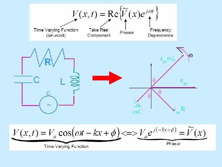
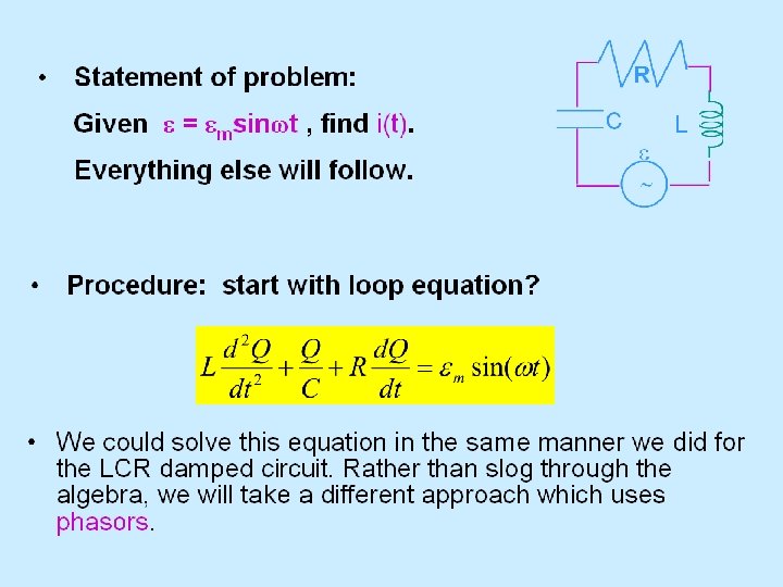
Steady-State Sinusoidal Analysis • Also known as AC steady-state • Any steady state voltage or current in a linear circuit with a sinusoidal source is a sinusoid. – This is a consequence of the nature of particular solutions for sinusoidal forcing functions. • All AC steady state voltages and currents have the same frequency as the source. • In order to find a steady state voltage or current, all we need to know is its magnitude and its phase relative to the source – We already know its frequency. • Usually, an AC steady state voltage or current is given by the particular solution to a differential equation.
The Good News! • We do not have to find this differential equation from the circuit, nor do we have to solve it. • Instead, we use the concepts of phasors and complex impedances. • Phasors and complex impedances convert problems involving differential equations into circuit analysis problems.
Phasors • A phasor is a complex number that represents the magnitude and phase of a sinusoidal voltage or current. • Remember, for AC steady state analysis, this is all we need to compute-we already know the frequency of any voltage or current.
Complex Impedance • Complex impedance describes the relationship between the voltage across an element (expressed as a phasor) and the current through the element (expressed as a phasor). • Impedance is a complex number. • Impedance depends on frequency. • Phasors and complex impedance allow us to use Ohm’s law with complex numbers to compute current from voltage and voltage from current.
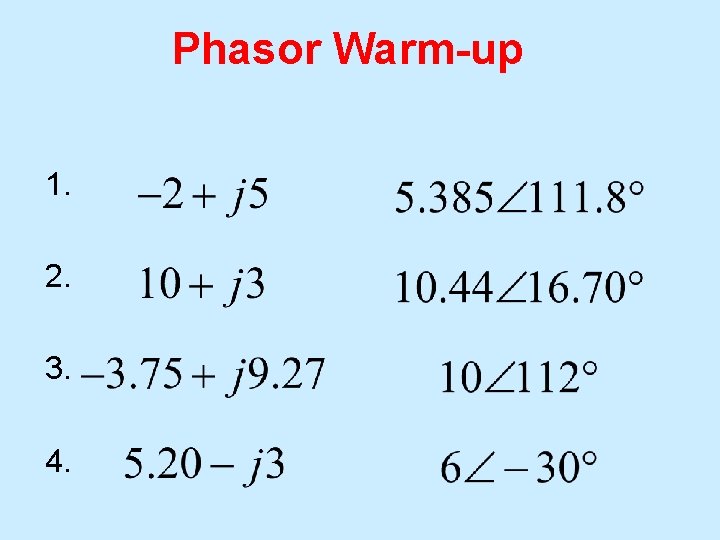
Phasor Warm-up 1. 2. 3. 4.
Phasor Relationships for Circuit Elements • We talk about AC circuits as being in the frequency domain when we use phasors. • How do we apply phasor relationships for voltage and current to the passive elements (resistors, capacitors, inductors)?
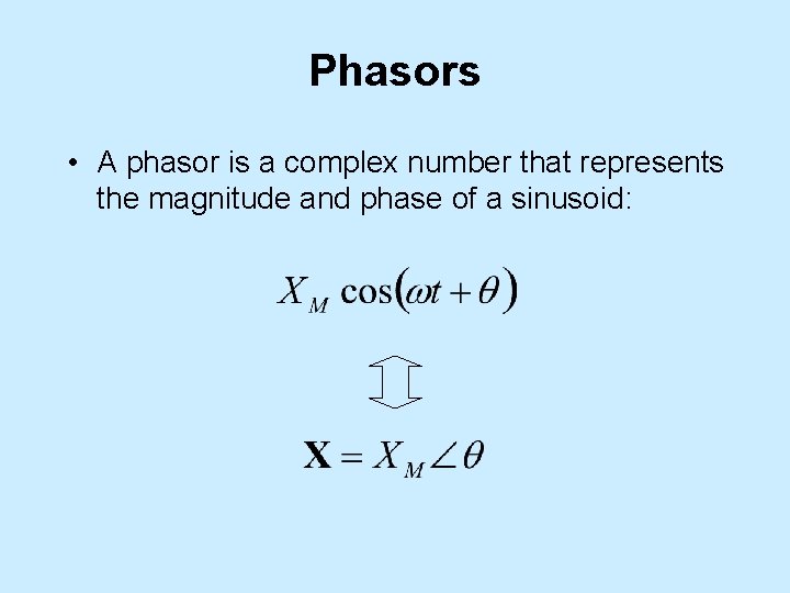
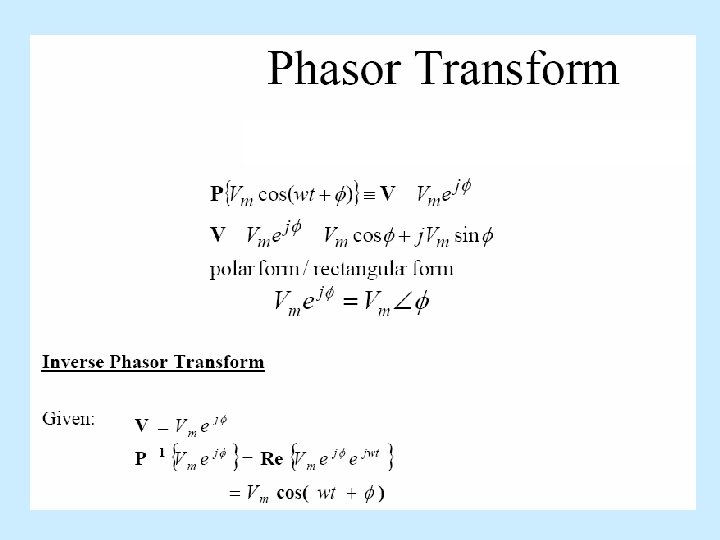
Phasors • A phasor is a complex number that represents the magnitude and phase of a sinusoid:
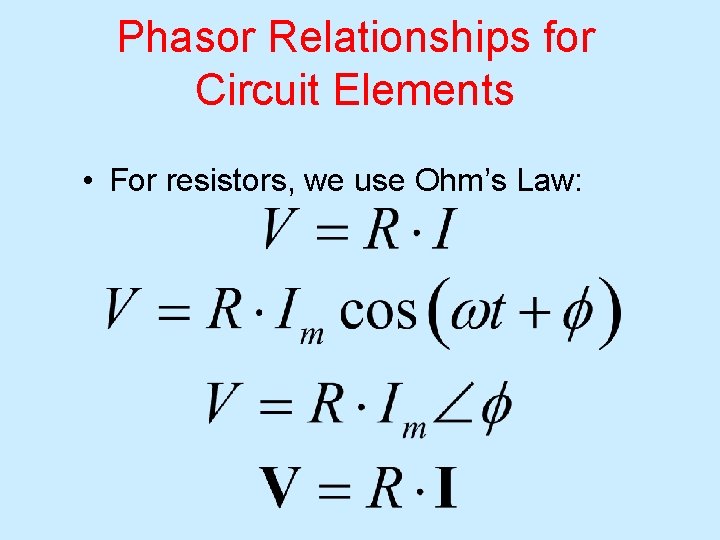
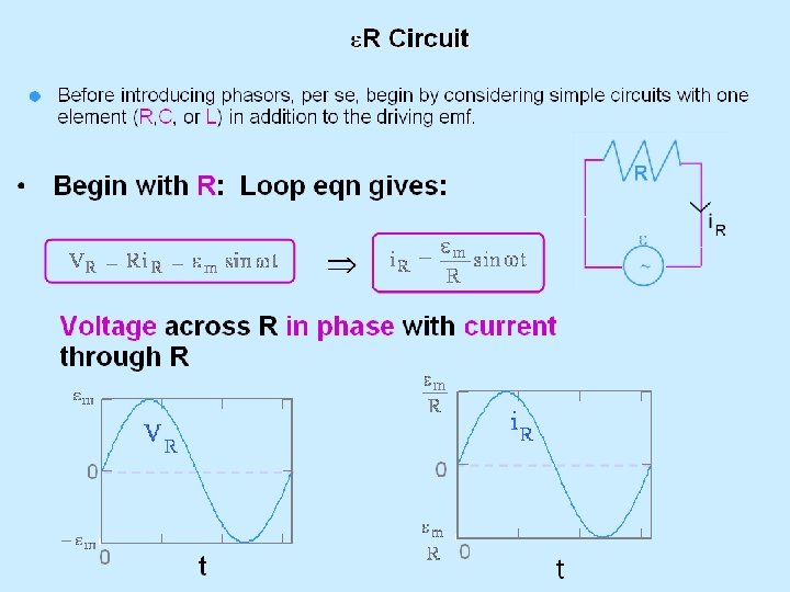
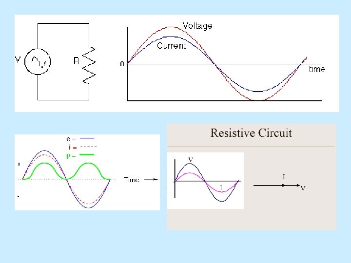
Phasor Relationships for Circuit Elements • For resistors, we use Ohm’s Law:

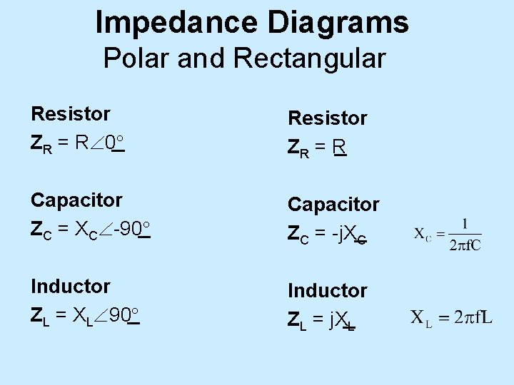
Impedance Diagrams Polar and Rectangular Resistor Z R = R 0 Resistor ZR = R Capacitor ZC = XC -90 Capacitor ZC = -j. XC Inductor ZL = XL 90 Inductor ZL = j. XL
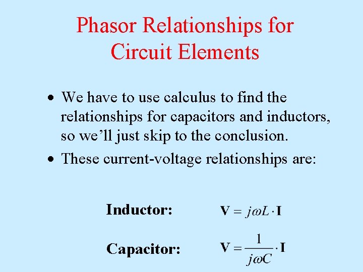
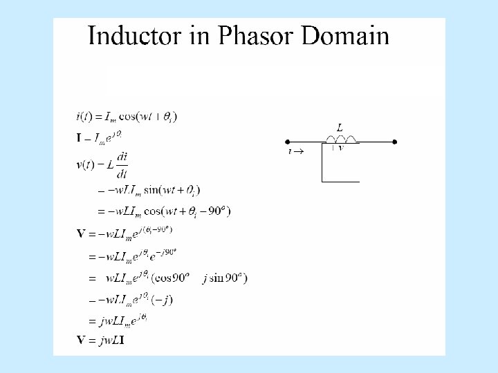
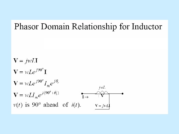
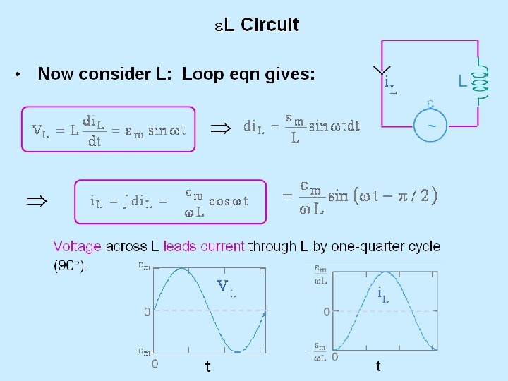
Phasor Relationships for Circuit Elements We have to use calculus to find the relationships for capacitors and inductors, so we’ll just skip to the conclusion. These current-voltage relationships are: Inductor: Capacitor:
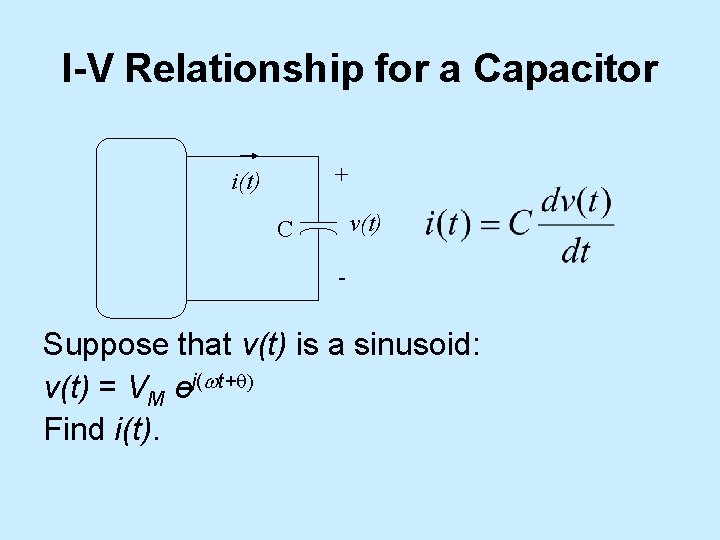
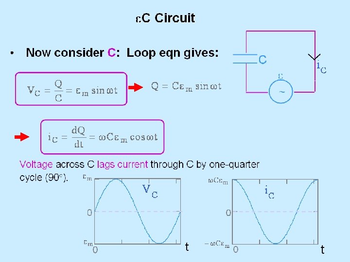
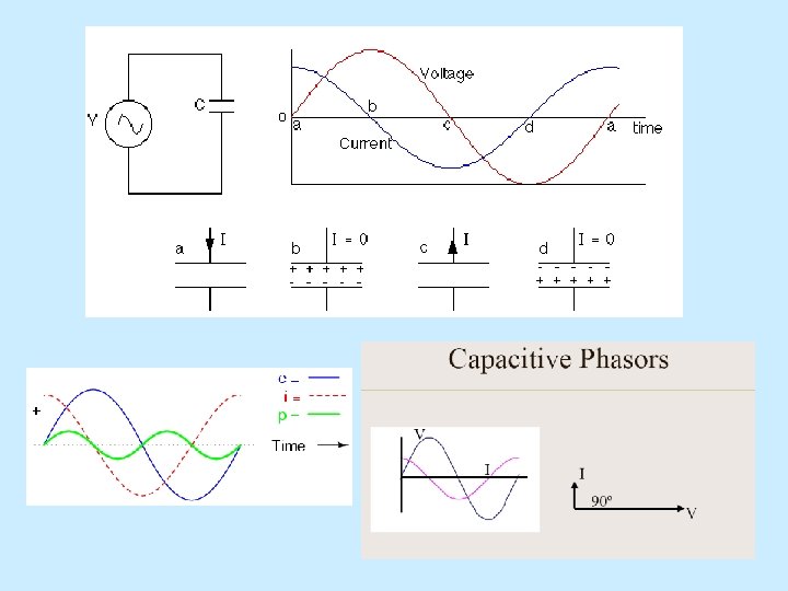
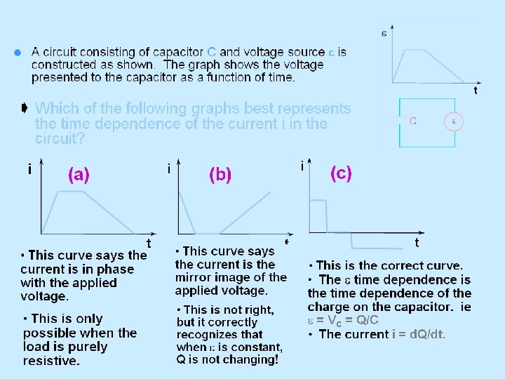
I-V Relationship for a Capacitor + i(t) v(t) C - Suppose that v(t) is a sinusoid: v(t) = VM ej(wt+q) Find i(t).
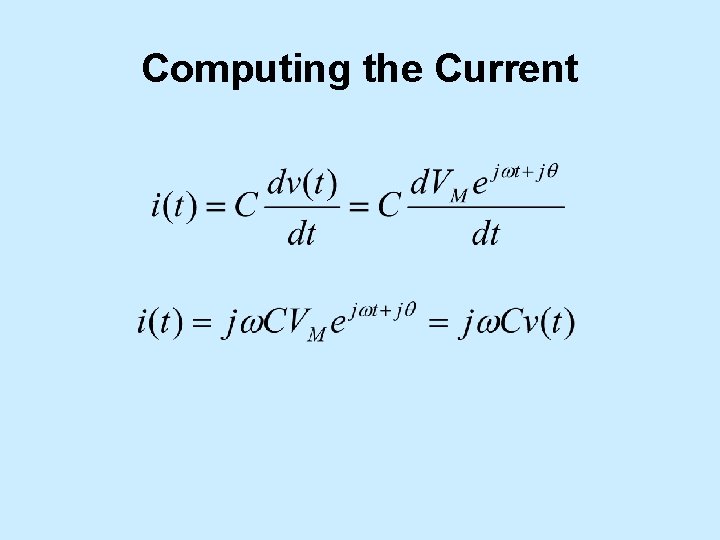
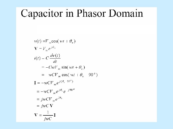
Computing the Current
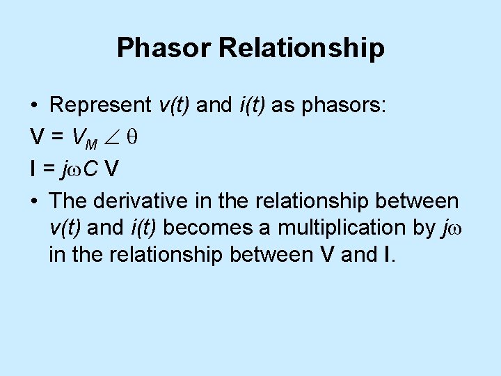
Phasor Relationship • Represent v(t) and i(t) as phasors: V = VM q I = jw. C V • The derivative in the relationship between v(t) and i(t) becomes a multiplication by jw in the relationship between V and I.
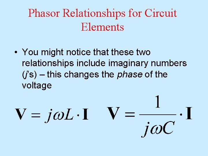
Phasor Relationships for Circuit Elements • You might notice that these two relationships include imaginary numbers (j’s) – this changes the phase of the voltage
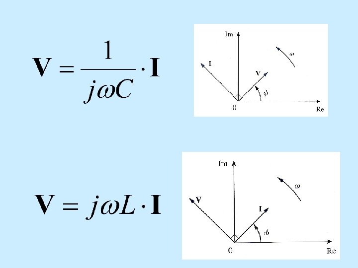
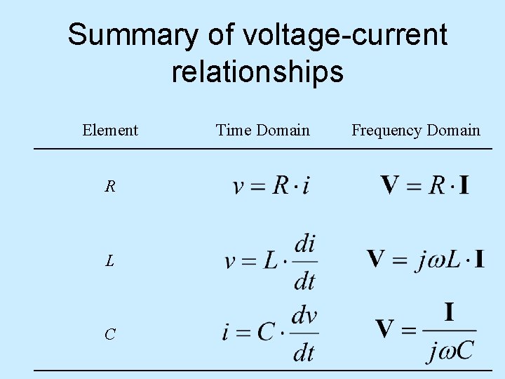
Summary of voltage-current relationships Element R L C Time Domain Frequency Domain
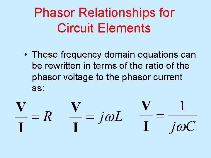
Phasor Relationships for Circuit Elements • These frequency domain equations can be rewritten in terms of the ratio of the phasor voltage to the phasor current as:
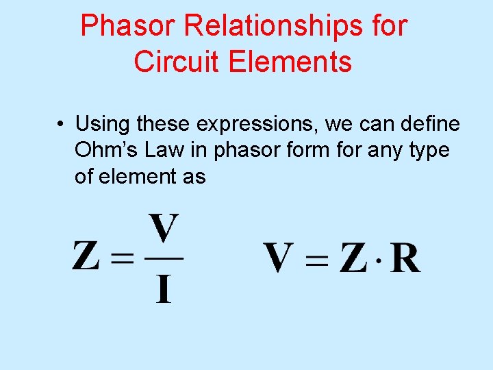
Phasor Relationships for Circuit Elements • Using these expressions, we can define Ohm’s Law in phasor form for any type of element as
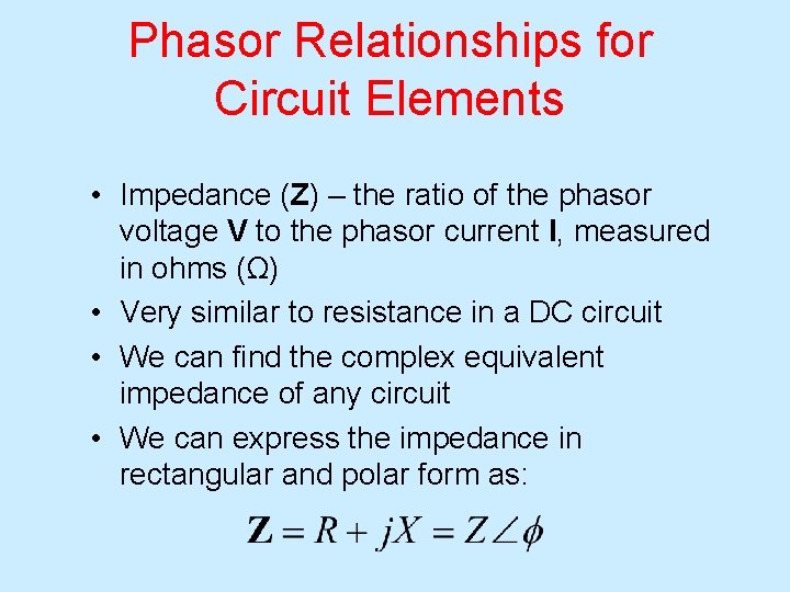
Phasor Relationships for Circuit Elements • Impedance (Z) – the ratio of the phasor voltage V to the phasor current I, measured in ohms (Ω) • Very similar to resistance in a DC circuit • We can find the complex equivalent impedance of any circuit • We can express the impedance in rectangular and polar form as:
Impedance • AC steady-state analysis using phasors allows us to express the relationship between current and voltage using a formula that looks likes Ohm’s law: V=IZ • Z is called impedance.

Impedance (cont’d) Impedance depends on the frequency w. Impedance is (often) a complex number. Impedance is not a phasor (why? ). Impedance allows us to use the same solution techniques for AC steady state as we use for DC steady state. • Impedance in series/parallel can be combined as resistors • •
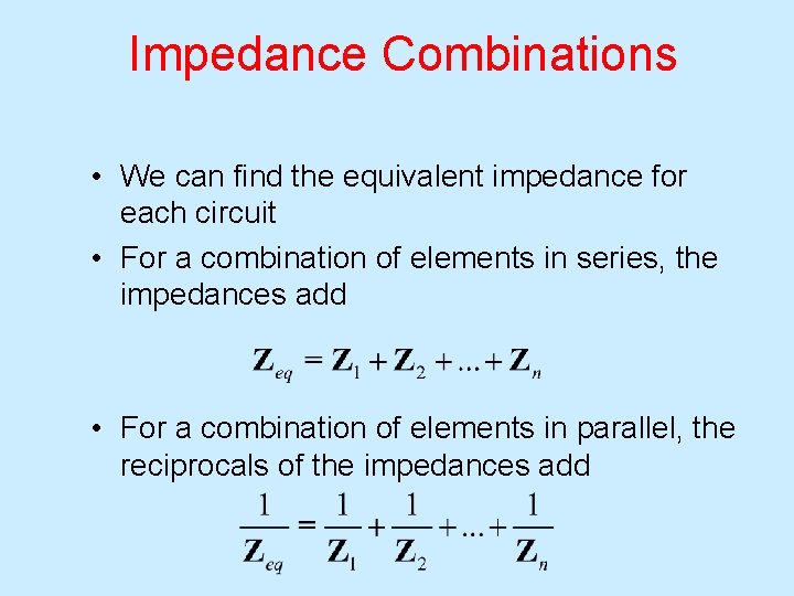
Impedance Combinations • We can find the equivalent impedance for each circuit • For a combination of elements in series, the impedances add • For a combination of elements in parallel, the reciprocals of the impedances add
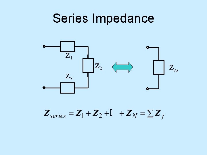
Series Impedance Z 1 Z 2 Z 3 Zeq
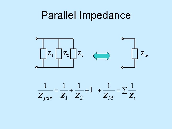
Parallel Impedance Z 1 Z 2 Z 3 Zeq
Kirchoff’s Laws in the Frequency Domain • Kirchoff’s current and voltage laws are the same in the frequency domain as they are in DC circuits – only this time the current and voltages are phasors • These laws can be used in the frequency domain to analyze AC circuits as long as the circuit has only one angular frequency

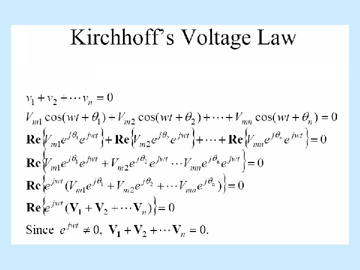
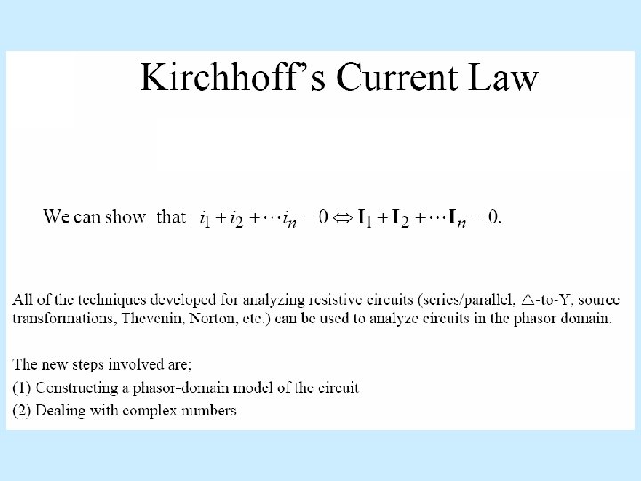
Kirchoff’s Laws in the Frequency Domain • Kirchoff’s Voltage Law: • Kirchoff’s Current Law: (or Current In = Current Out)
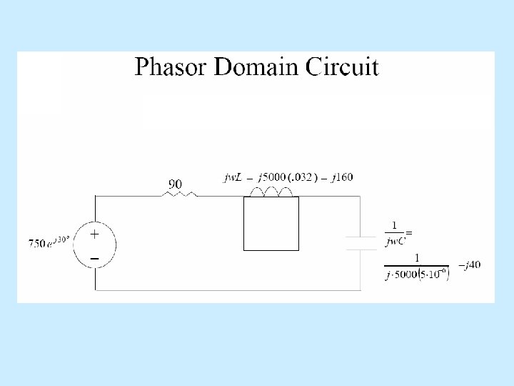

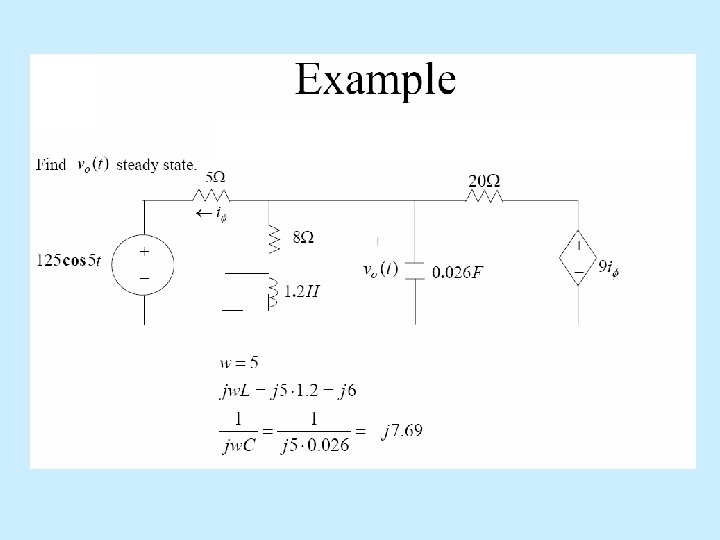
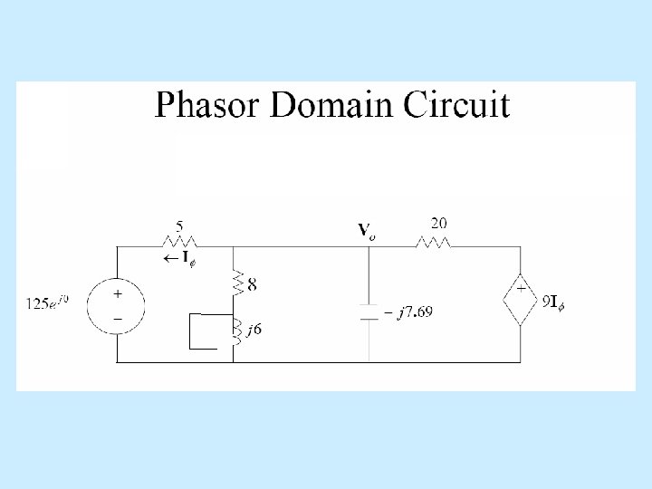
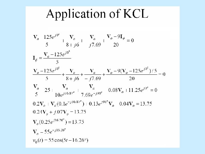
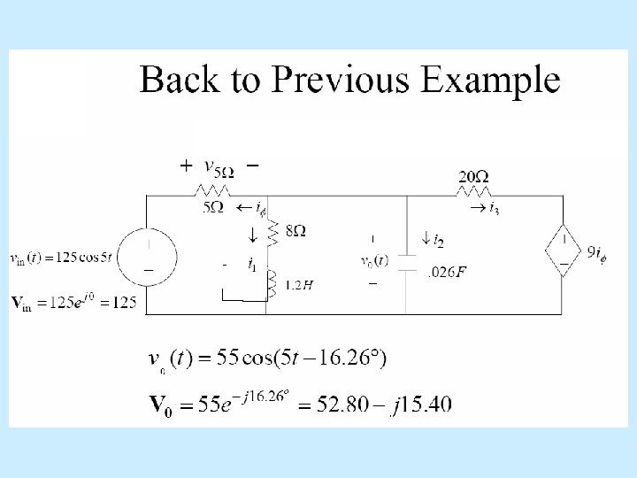
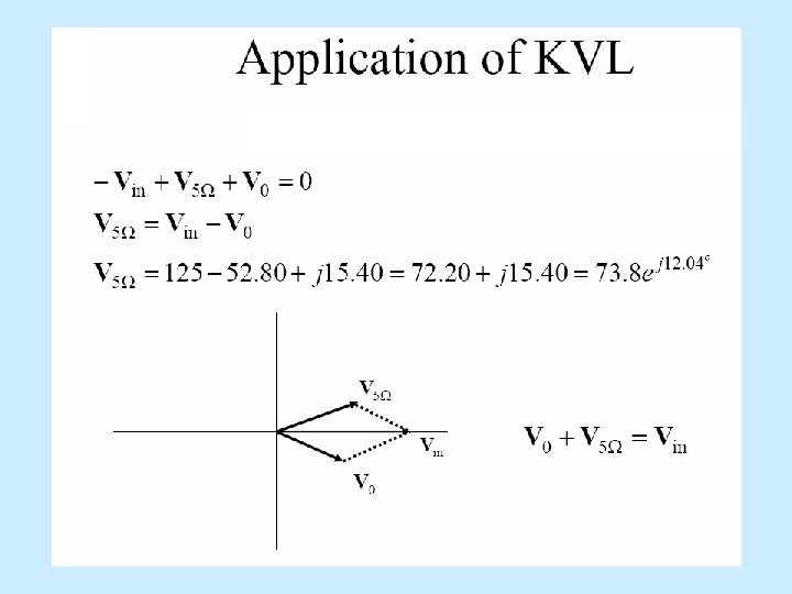
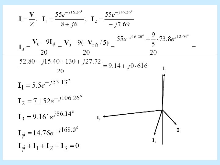
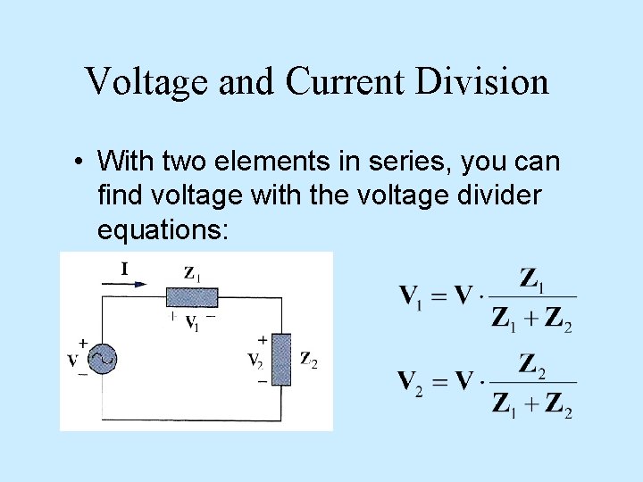
Voltage and Current Division • With two elements in series, you can find voltage with the voltage divider equations:
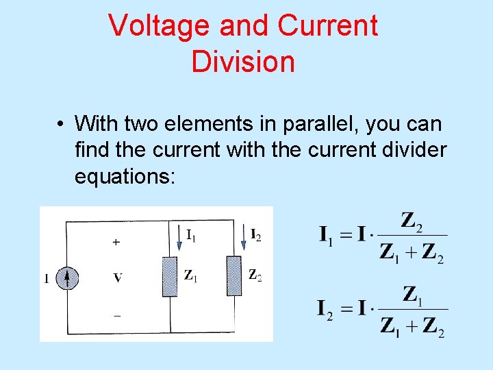
Voltage and Current Division • With two elements in parallel, you can find the current with the current divider equations:
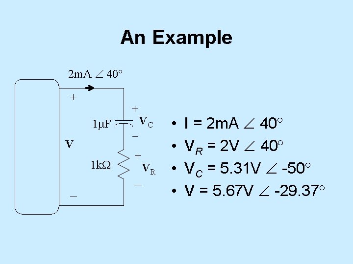
An Example 2 m. A 40 + + 1 m. F V 1 k. W – – VC + – VR • • I = 2 m. A 40 VR = 2 V 40 VC = 5. 31 V -50 V = 5. 67 V -29. 37
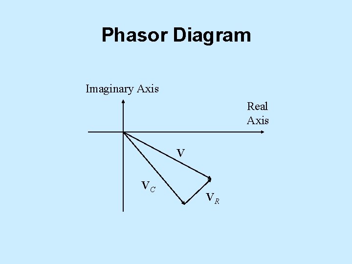
Phasor Diagram Imaginary Axis Real Axis V VC VR
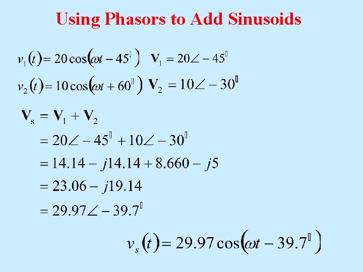
Using Phasors to Add Sinusoids
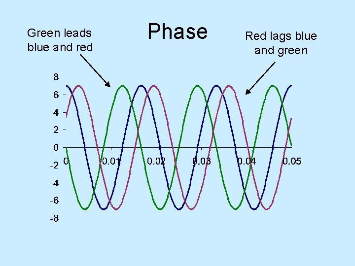
Green leads blue and red Phase Red lags blue and green
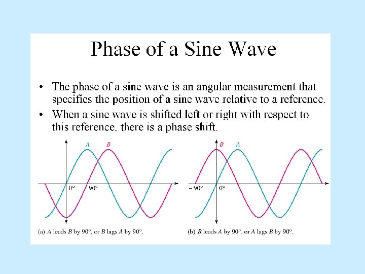
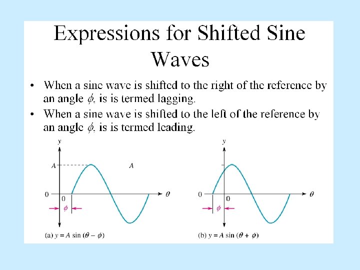
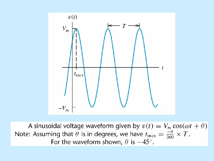
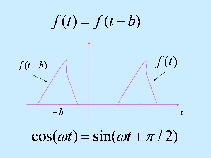


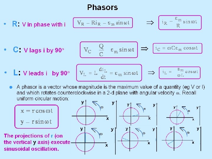
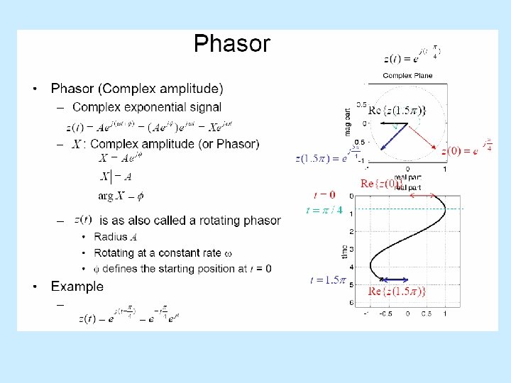
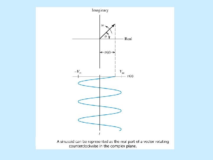
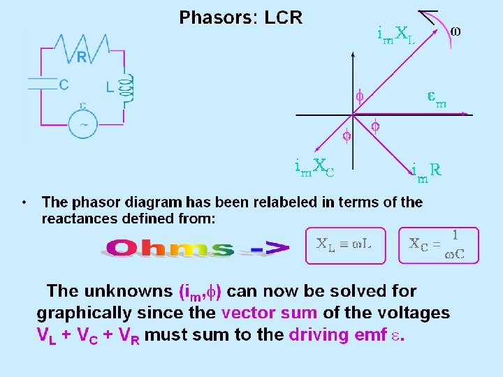
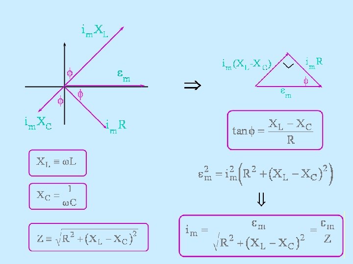
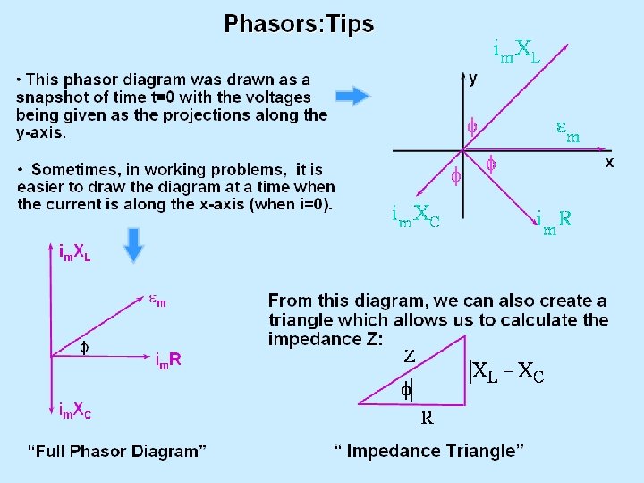
Sinusoids can be visualized as the realaxis projection of vectors rotating in the complex plane. The phasor for a sinusoid is a snapshot of the corresponding rotating vector at t = 0.
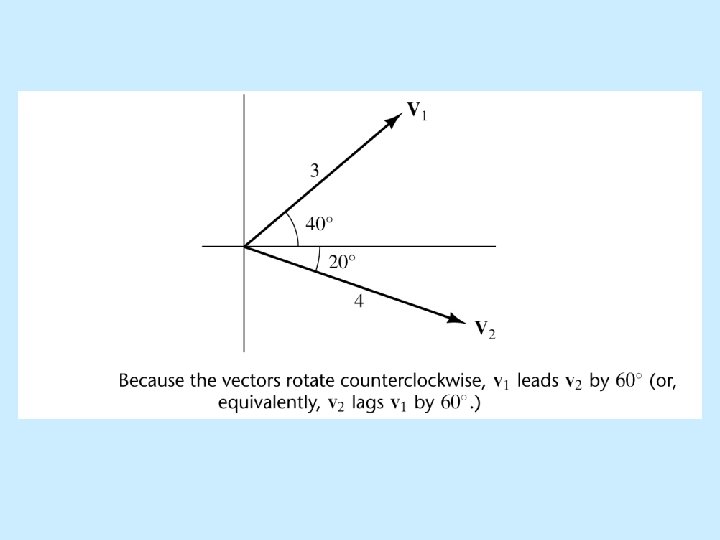
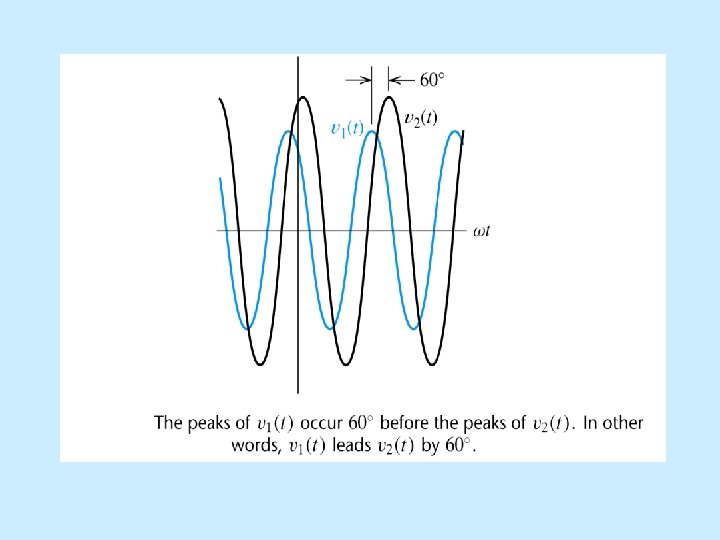

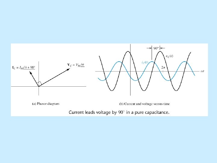
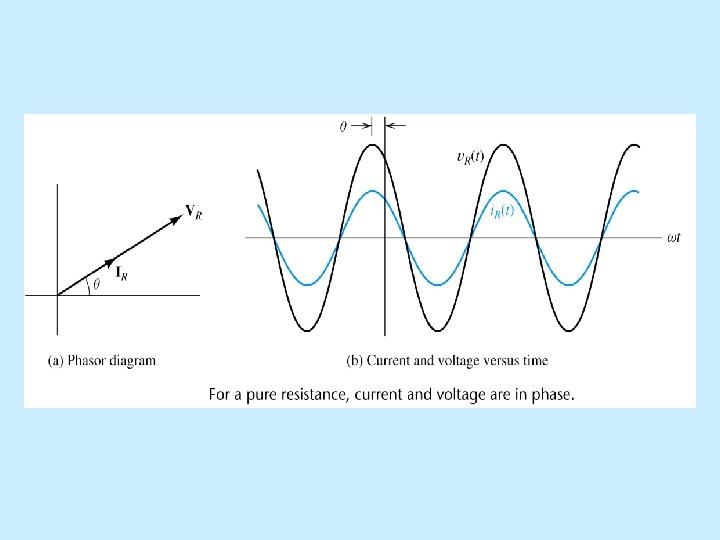
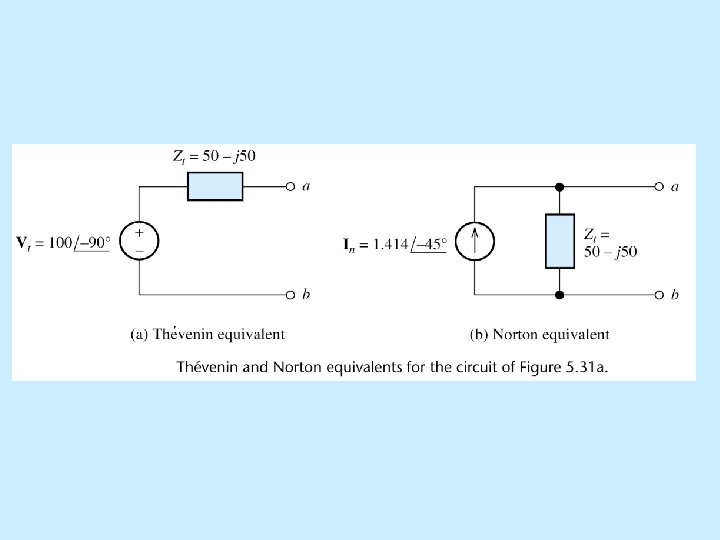
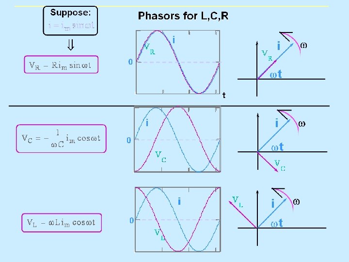
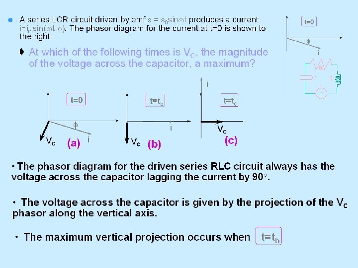
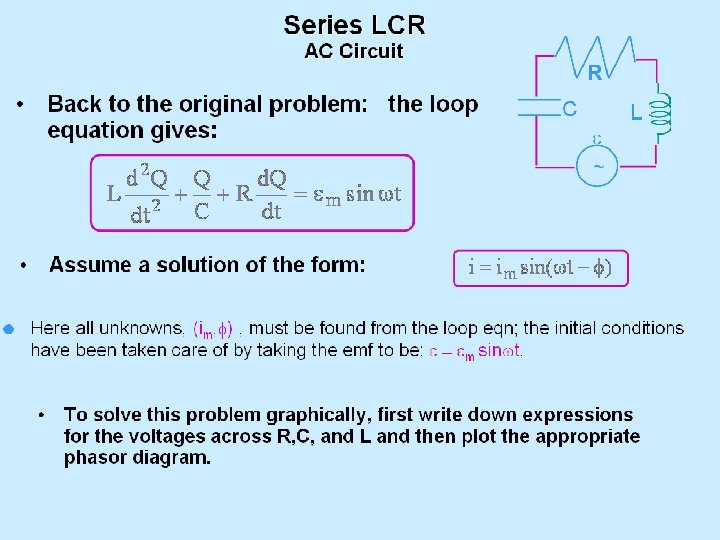
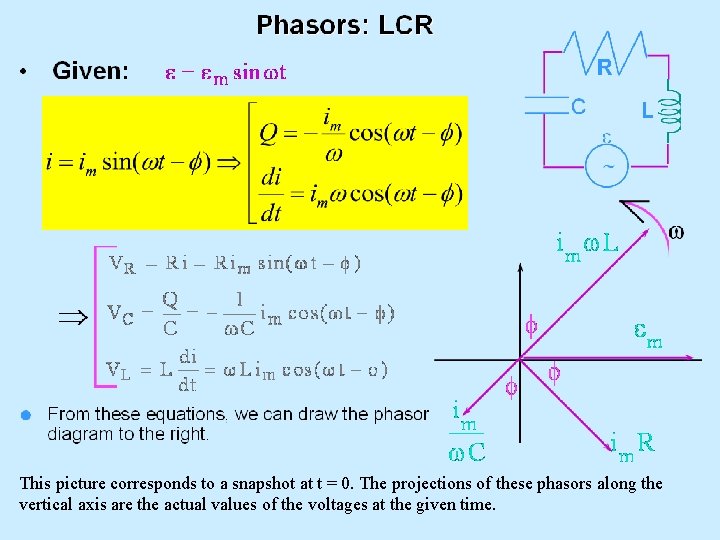
This picture corresponds to a snapshot at t = 0. The projections of these phasors along the vertical axis are the actual values of the voltages at the given time.

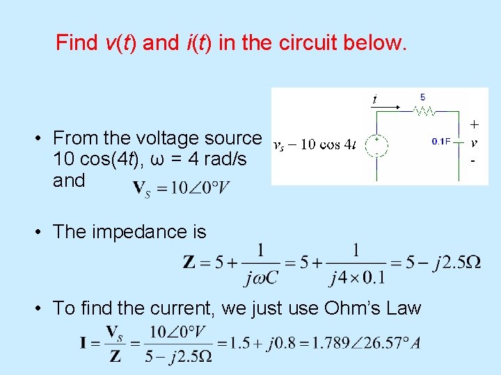
Find v(t) and i(t) in the circuit below. • From the voltage source 10 cos(4 t), ω = 4 rad/s and • The impedance is • To find the current, we just use Ohm’s Law

Find v(t) and i(t) in the circuit below. • The voltage across the capacitor is • Converting I and V to the time domain, we get

Determine v(t) and i(t). • The voltage phasor is • The equivalent impedance is
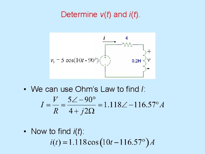
Determine v(t) and i(t). • We can use Ohm’s Law to find I: • Now to find i(t):

Determine v(t) and i(t). • To find VL, we use Ohm’s Law again, across the inductor:
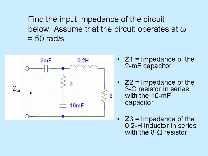
Find the input impedance of the circuit below. Assume that the circuit operates at ω = 50 rad/s. • Z 1 = Impedance of the 2 -m. F capacitor • Z 2 = Impedance of the 3 -Ω resistor in series with the 10 -m. F capacitor • Z 3 = Impedance of the 0. 2 -H inductor in series with the 8 -Ω resistor
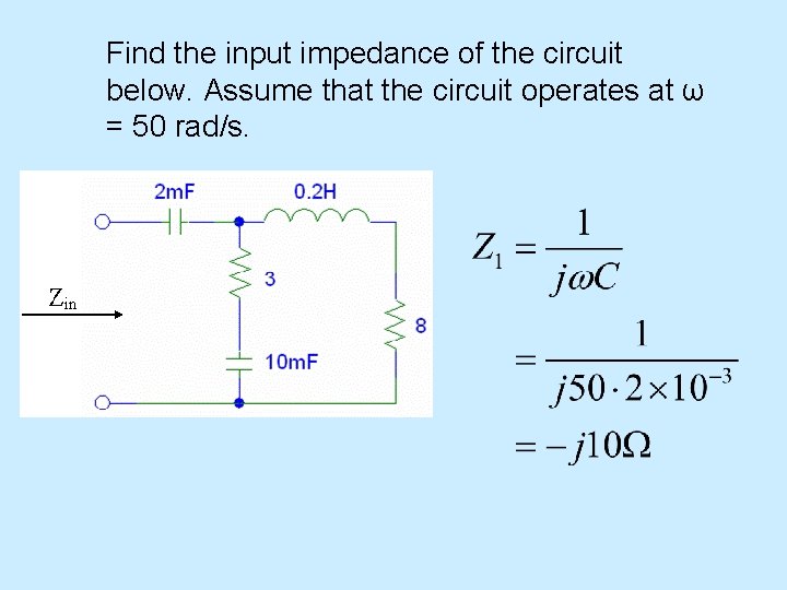
Find the input impedance of the circuit below. Assume that the circuit operates at ω = 50 rad/s.
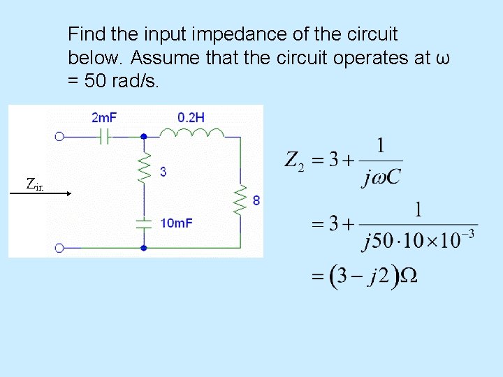
Find the input impedance of the circuit below. Assume that the circuit operates at ω = 50 rad/s.
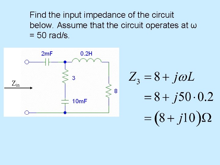
Find the input impedance of the circuit below. Assume that the circuit operates at ω = 50 rad/s.
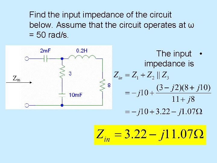
Find the input impedance of the circuit below. Assume that the circuit operates at ω = 50 rad/s. The input • impedance is
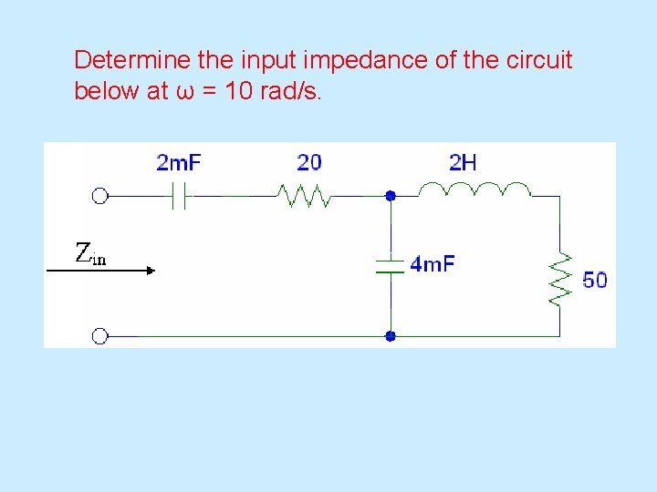
Determine the input impedance of the circuit below at ω = 10 rad/s.
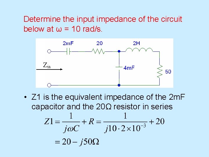
Determine the input impedance of the circuit below at ω = 10 rad/s. • Z 1 is the equivalent impedance of the 2 m. F capacitor and the 20Ω resistor in series

Determine the input impedance of the circuit below at ω = 10 rad/s. • Z 2 is the impedance of the 4 m. F capacitor
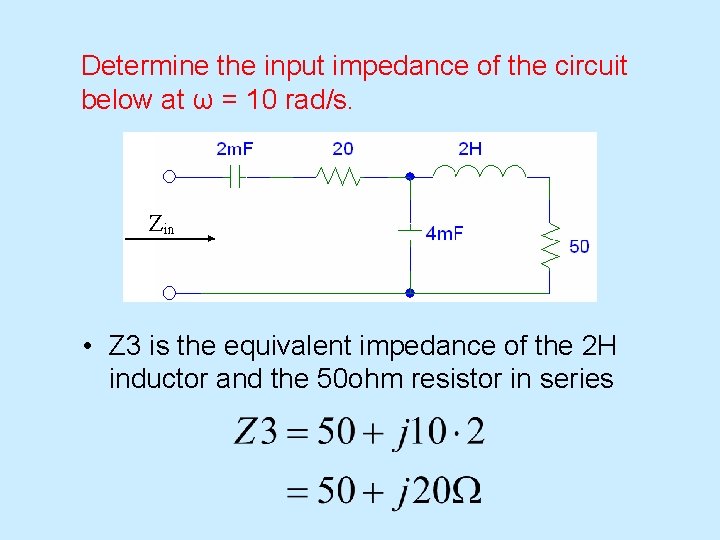
Determine the input impedance of the circuit below at ω = 10 rad/s. • Z 3 is the equivalent impedance of the 2 H inductor and the 50 ohm resistor in series

Determine the input impedance of the circuit below at ω = 10 rad/s. • Now Zin is the combination of Z 1, Z 2, & Z 3:

Example: Single Loop Circuit 10 V 0 + - 20 k. W 1 m. F + - VC w = 377 Find VC How do we find VC? First compute impedances for resistor and capacitor: ZR = 20 k. W 0 ZC = 1/j (377 1 m. F) = 2. 65 k. W -90
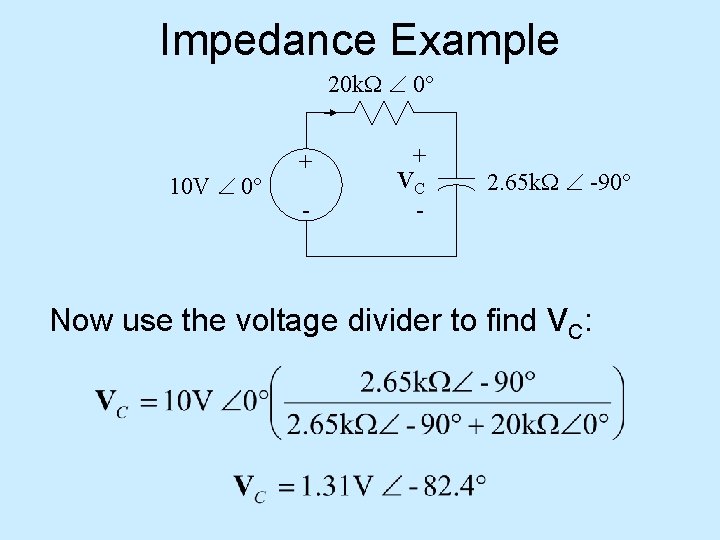
Impedance Example 20 k. W 0 10 V 0 + - + VC - 2. 65 k. W -90 Now use the voltage divider to find VC:
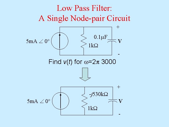
Low Pass Filter: A Single Node-pair Circuit + 5 m. A 0 0. 1 m. F 1 k. W V - Find v(t) for w=2 p 3000 + -j 530 k. W 5 m. A 0 V 1 k. W -

Find the Equivalent Impedance + 5 m. A 0 Zeq V -
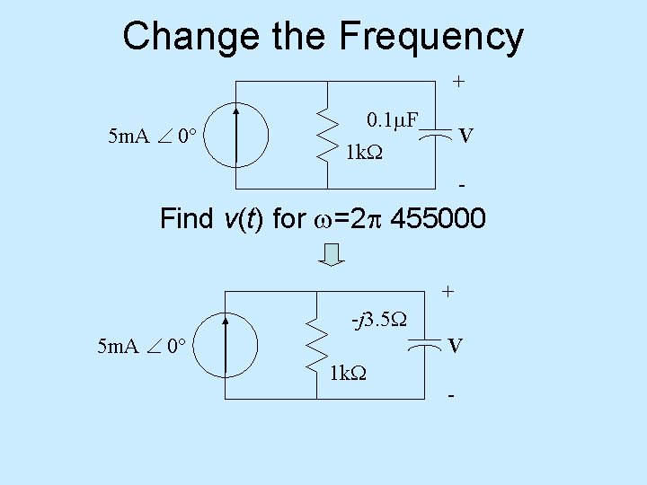
Change the Frequency + 5 m. A 0 0. 1 m. F 1 k. W V - Find v(t) for w=2 p 455000 + -j 3. 5 W 5 m. A 0 V 1 k. W -
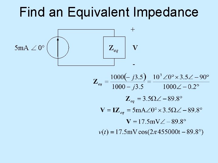
Find an Equivalent Impedance + 5 m. A 0 Zeq V -


Questions? Discussion? Suggestions ?

- Slides: 110