
Lecture 03 AC RESPONSE REACTANCE N IMPEDANCE AC






- Slides: 44
Lecture 03: AC RESPONSE ( REACTANCE N IMPEDANCE )
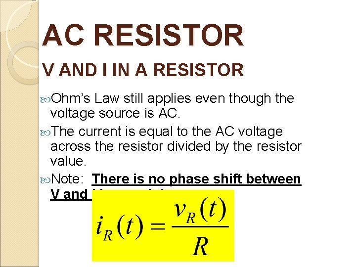
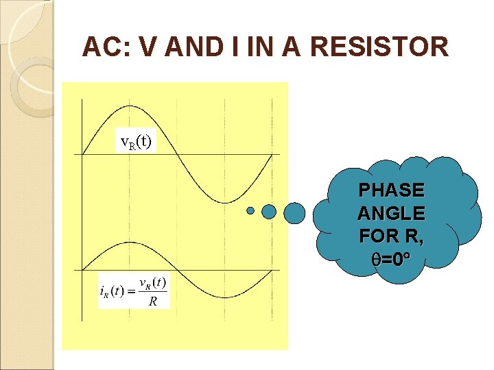
AC RESISTOR V AND I IN A RESISTOR Ohm’s Law still applies even though the voltage source is AC. The current is equal to the AC voltage across the resistor divided by the resistor value. Note: There is no phase shift between V and I in a resistor.
AC: V AND I IN A RESISTOR v. R(t) PHASE ANGLE FOR R, =0
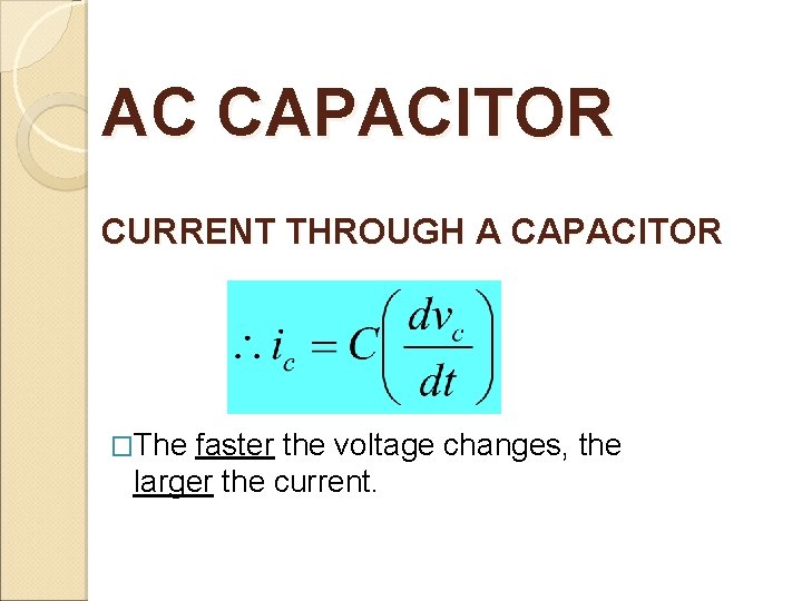
AC CAPACITOR CURRENT THROUGH A CAPACITOR �The faster the voltage changes, the larger the current.
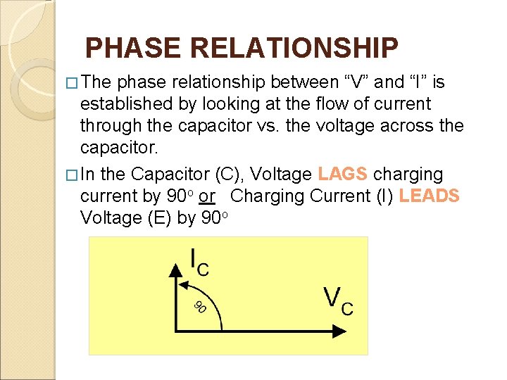
PHASE RELATIONSHIP � The phase relationship between “V” and “I” is established by looking at the flow of current through the capacitor vs. the voltage across the capacitor. � In the Capacitor (C), Voltage LAGS charging current by 90 o or Charging Current (I) LEADS Voltage (E) by 90 o
Graph v. C(t) and i. C(t) vc(t) 90° ic (t) Note: Phase relationship of I and V in a capacitor
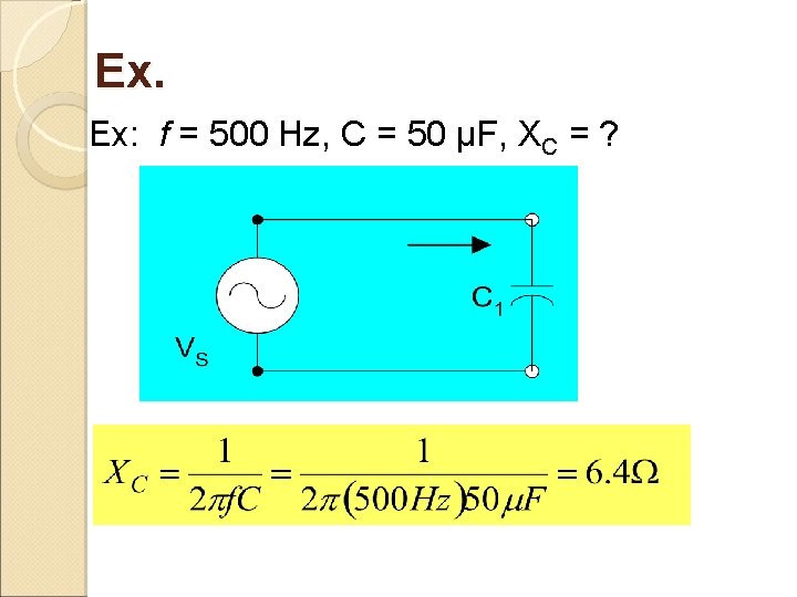
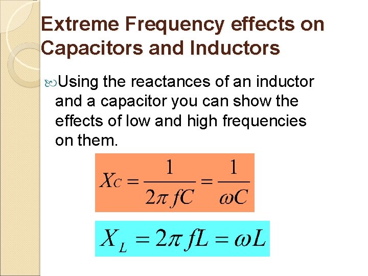
CAPACITIVE REACTANCE In resistor, the Ohm’s Law is V=IR, where R is the opposition to current. We will define Capacitive Reactance, XC, as the opposition to current in a capacitor. XC will have units of Ohms. Note inverse proportionality to f and C. Magnitude of XC
Ex. Ex: f = 500 Hz, C = 50 µF, XC = ?
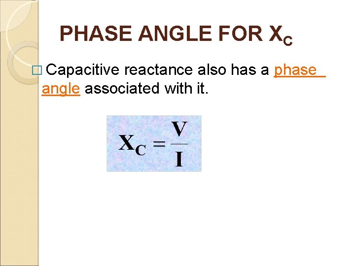
PHASE ANGLE FOR XC � Capacitive reactance also has a phase angle associated with it.
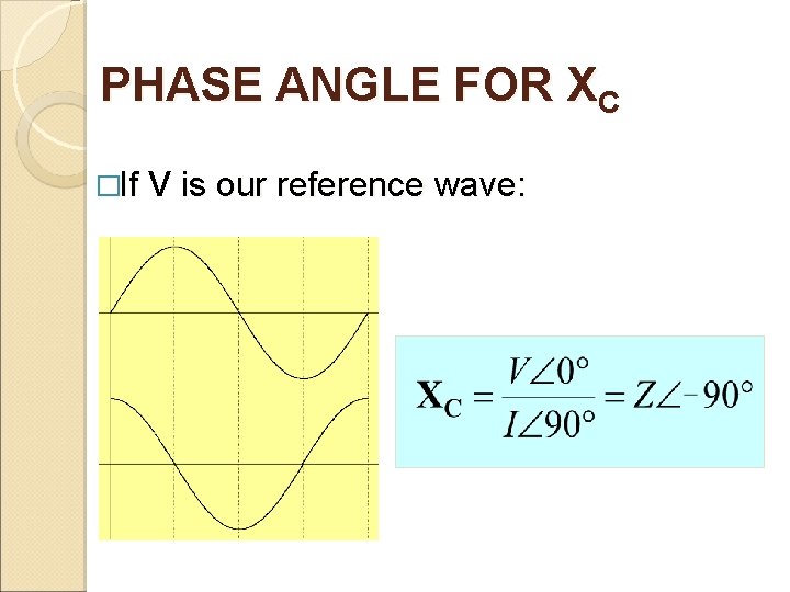
PHASE ANGLE FOR XC �If V is our reference wave:
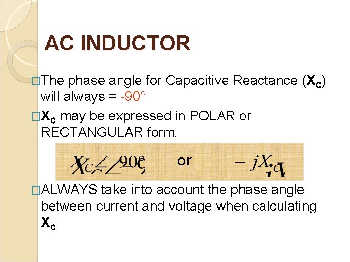
AC INDUCTOR �The phase angle for Capacitive Reactance (XC) will always = -90° �XC may be expressed in POLAR or RECTANGULAR form. or �ALWAYS take into account the phase angle between current and voltage when calculating XC
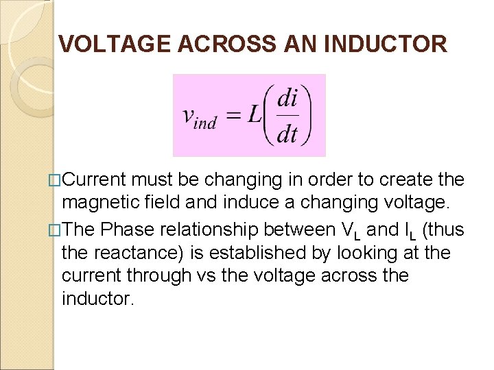
VOLTAGE ACROSS AN INDUCTOR �Current must be changing in order to create the magnetic field and induce a changing voltage. �The Phase relationship between VL and IL (thus the reactance) is established by looking at the current through vs the voltage across the inductor.
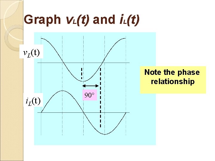
Graph v. L(t) and i. L(t) v. L(t) Note the phase relationship i. L(t) 90°
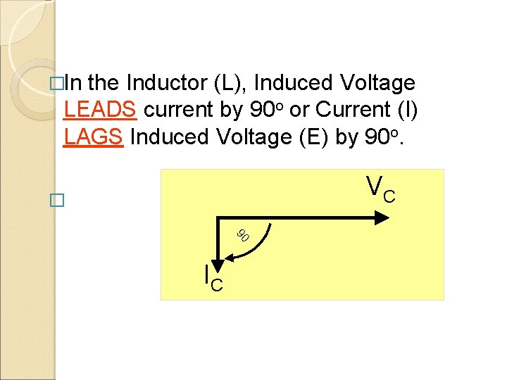
�In the Inductor (L), Induced Voltage LEADS current by 90 o or Current (I) LAGS Induced Voltage (E) by 90 o. VC � 90 IC
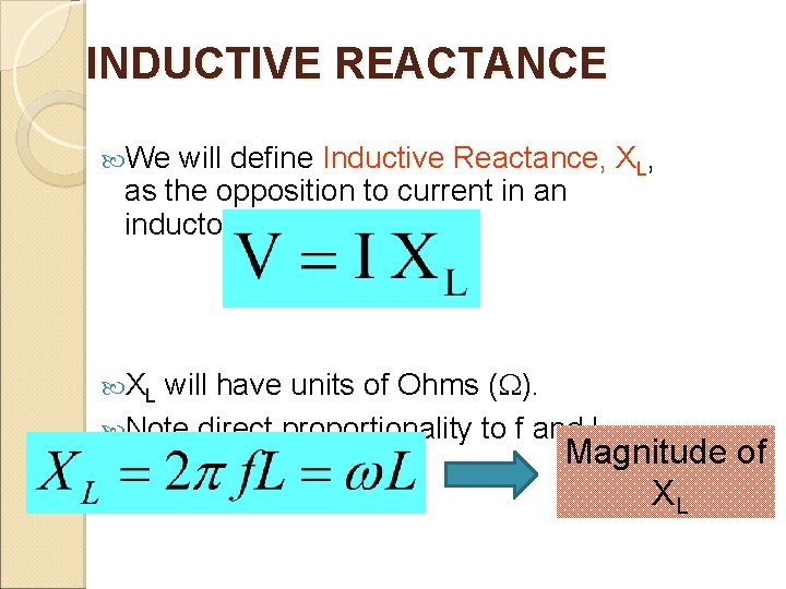
INDUCTIVE REACTANCE We will define Inductive Reactance, XL, as the opposition to current in an inductor. XL will have units of Ohms (W). Note direct proportionality to f and L. Magnitude of XL
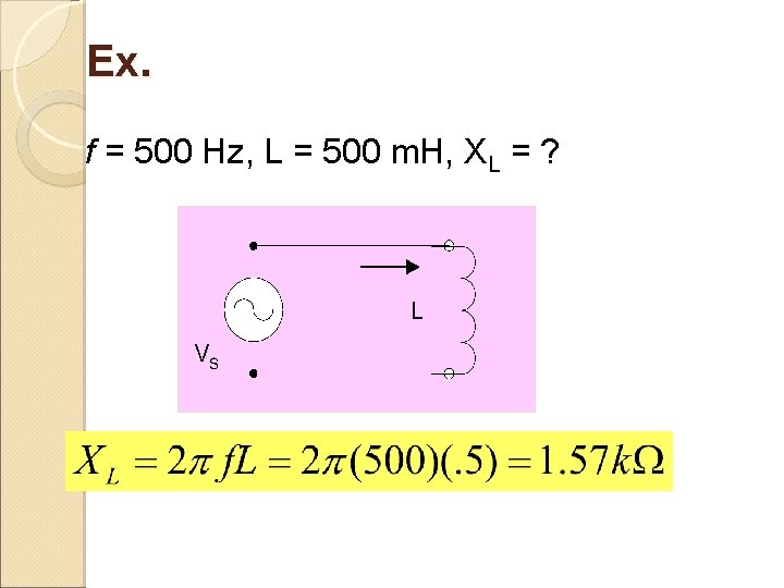
Ex. f = 500 Hz, L = 500 m. H, XL = ?
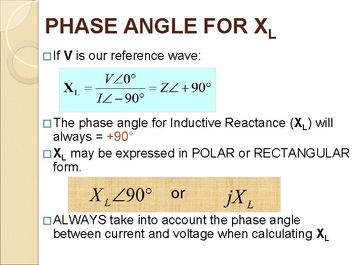
PHASE ANGLE FOR XL � If V is our reference wave: � The phase angle for Inductive Reactance (XL) will always = +90° � XL may be expressed in POLAR or RECTANGULAR form. or � ALWAYS take into account the phase angle between current and voltage when calculating XL
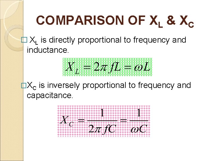
COMPARISON OF XL & XC � XL is directly proportional to frequency and inductance. �XC is inversely proportional to frequency and capacitance.
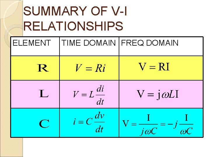
SUMMARY OF V-I RELATIONSHIPS ELEMENT TIME DOMAIN FREQ DOMAIN
Extreme Frequency effects on Capacitors and Inductors Using the reactances of an inductor and a capacitor you can show the effects of low and high frequencies on them.
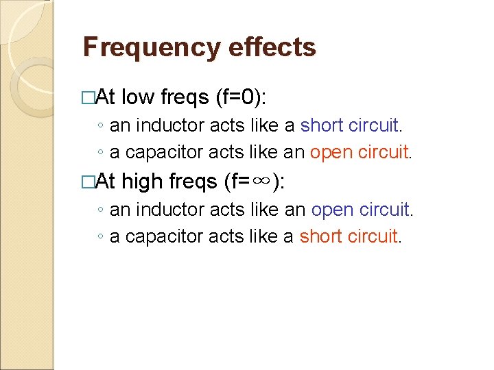
Frequency effects �At low freqs (f=0): ◦ an inductor acts like a short circuit. ◦ a capacitor acts like an open circuit. �At high freqs (f=∞): ◦ an inductor acts like an open circuit. ◦ a capacitor acts like a short circuit.
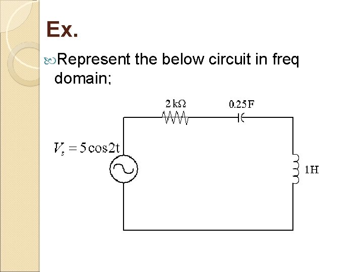
Ex. Represent domain; the below circuit in freq
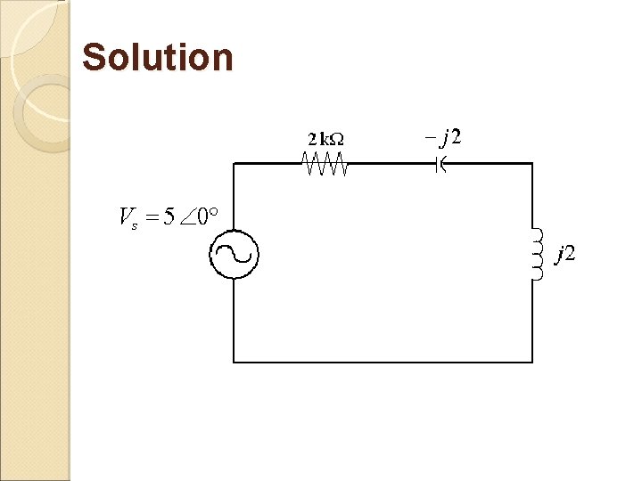
Solution =2 rad/s: Time domain Freq domain R=2Ω C = 0. 25 F XC = -j(1/ C) = -j 2 Ω L=1 H XL = j 2 Ω Vs = 5 cos 2 t Vs = 5<0
Solution
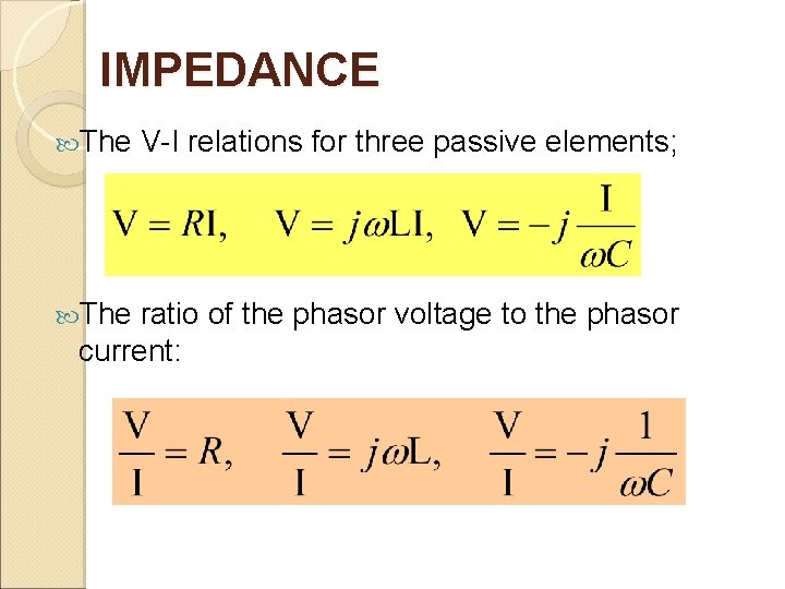
IMPEDANCE The V-I relations for three passive elements; ratio of the phasor voltage to the phasor current:
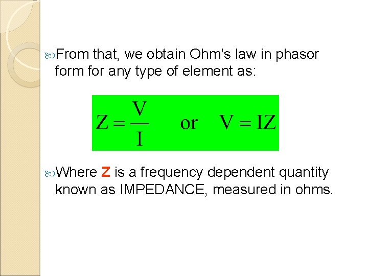
From that, we obtain Ohm’s law in phasor form for any type of element as: Where Z is a frequency dependent quantity known as IMPEDANCE, measured in ohms.
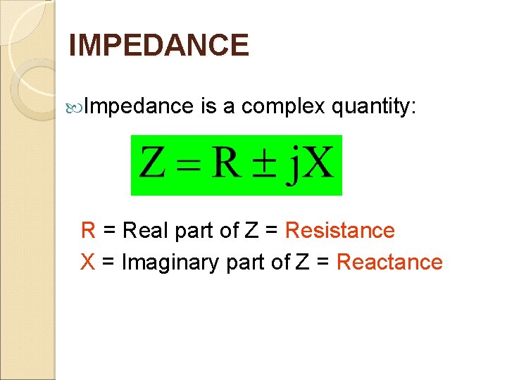
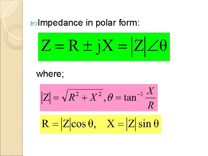
IMPEDANCE Impedance is a complex quantity: R = Real part of Z = Resistance X = Imaginary part of Z = Reactance
Impedance where; in polar form:
IMPEDANCES SUMMARY Impedance Phasor form: Rectangular form ZR R+j 0 ZL 0+j. XL ZC 0 -j. XC
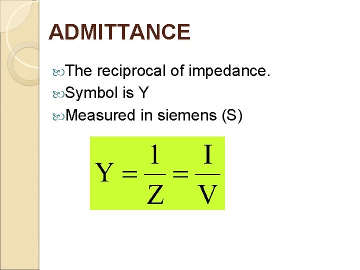
ADMITTANCE The reciprocal of impedance. Symbol is Y Measured in siemens (S)
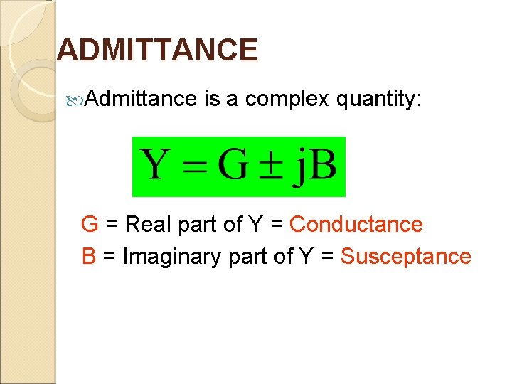
ADMITTANCE Admittance is a complex quantity: G = Real part of Y = Conductance B = Imaginary part of Y = Susceptance
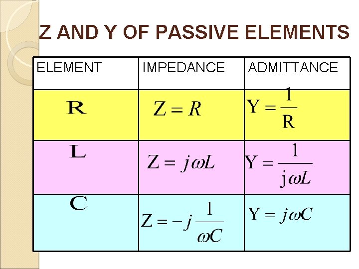
Z AND Y OF PASSIVE ELEMENTS ELEMENT IMPEDANCE ADMITTANCE
TOTAL IMPEDANCE FOR AC CIRCUITS �To compute total circuit impedance in AC circuits, use the same techniques as in DC. The only difference is that instead of using resistors, you now have to use complex impedance, Z.
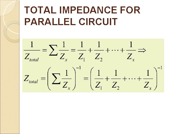
TOTAL IMPEDANCE FOR PARALLEL CIRCUIT
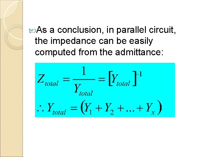
As a conclusion, in parallel circuit, the impedance can be easily computed from the admittance:
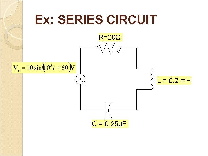
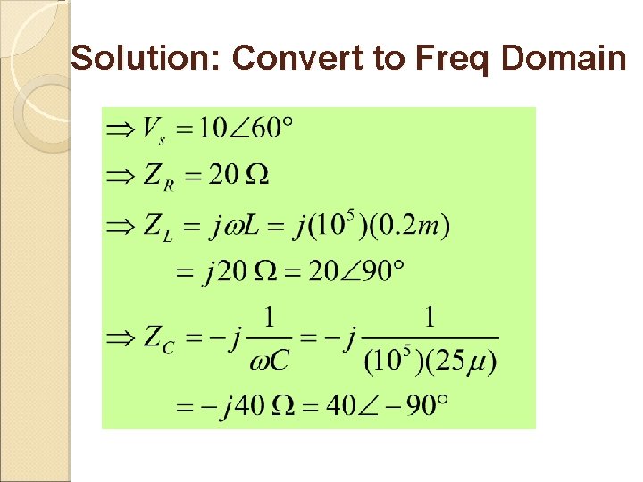
Ex: SERIES CIRCUIT R=20Ω L = 0. 2 m. H C = 0. 25μF
Solution: Convert to Freq Domain
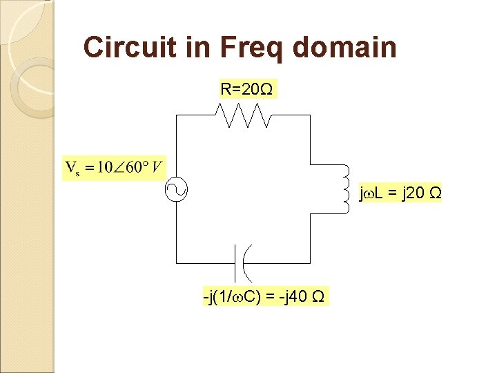
Circuit in Freq domain R=20Ω j L = j 20 Ω -j(1/ C) = -j 40 Ω
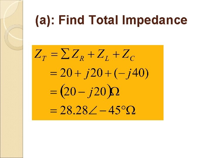
(a): Find Total Impedance
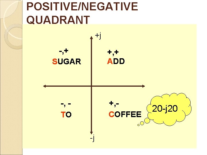
POSITIVE/NEGATIVE QUADRANT +j -, + SUGAR +, + ADD -, TO +, COFFEE -j 20
(b): Draw Impedance Triangle R j XC -j ZT R ZT XC
(c): Find is, v. R, v. C, v. L
Cont…. (c): Find is, v. R, v. C, v. L Remember to convert to RMS values when converting from sinusoid to phasors.
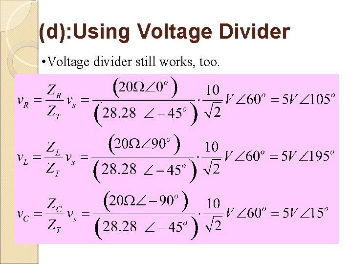
(d): Using Voltage Divider • Voltage divider still works, too.