Protection of Power Systems 8 Impedance Distance Relays
 Relays")


 Relays n Coordinating time-delay overcurrent relays can also be")


, a modified impedance relay is obtained by offsetting the")


, the n n impedance to")

- Slides: 43
Protection of Power Systems 8. Impedance (Distance) Relays
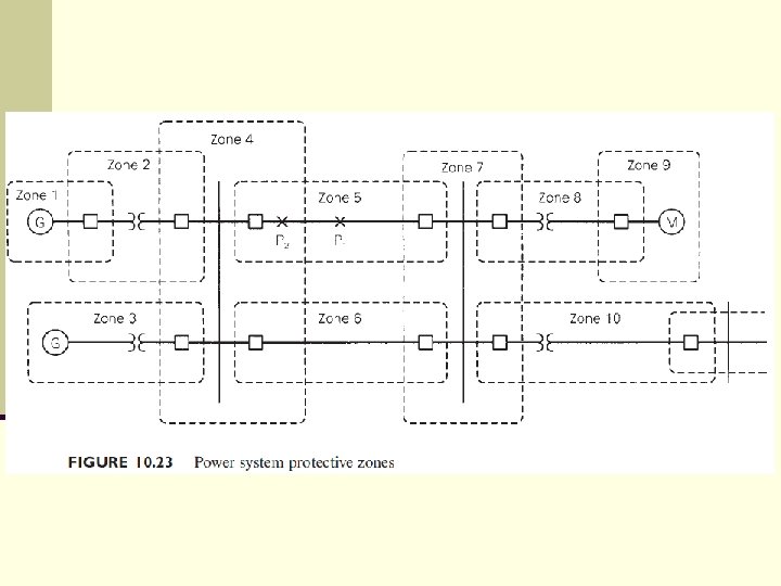
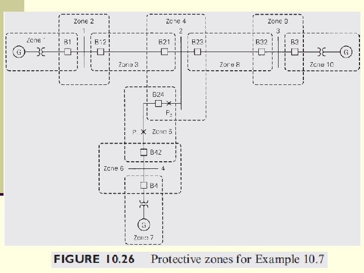
Zones of Protection n Protection of simple systems has been discussed so far. n For more general power system configurations, a fundamental concept is the division of a system into protective zones. n If a fault occurs anywhere within a zone, action will be taken to isolate that zone from the rest of the system. n Zones are defined for: generators, transformers, buses, transmission and distribution lines, and motors.
n Figure 10. 23 illustrates the protective zone concept. n Each zone is defined by a closed, dashed line. n Zone 1, for example, contains a generator and connecting leads to a transformer. n In some cases a zone may contain more than one component. n For example, zone 3 contains a generatortransformer unit and connecting leads to a bus, and zone 10 contains a transformer and a line.
n Protective zones have the following characteristics: Zones are overlapped. n Circuit breakers are located in the overlap regions. n For a fault anywhere in a zone, all circuit breakers in that zone open to isolate the fault. n Neighboring zones are overlapped to avoid the possibility of unprotected areas. n Without overlap the small area between two neighboring zones would not be located in any zone and thus would not be protected. n
n Since isolation during faults is done by circuit n n breakers, they should be inserted between equipment in a zone and each connection to the system. That is, breakers should be inserted in each overlap region. As such, they identify the boundaries of protective zones. For example, zone 5 in Figure 10. 23 is connected to zones 4 and 7. Therefore, a circuit breaker is located in the overlap region between zones 5 and 4, as well as between zones 5 and 7.
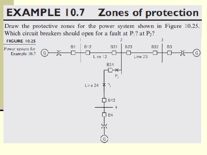
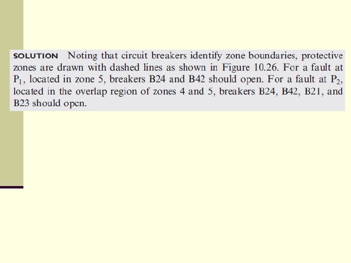
n If a fault occurs anywhere within a zone, action is n n taken to open all breakers in that zone. For example, if a fault occurs at P 1 on the line in zone 5, then the two breakers in zone 5 should open. If a fault occurs at P 2 within the overlap region of zones 4 and 5, then all five breakers in zones 4 and 5 should open. Clearly, if a fault occurs within an overlap region, two zones will be isolated and a larger part of the system will be lost from service. To minimize this possibility, overlap regions are kept as small as possible.
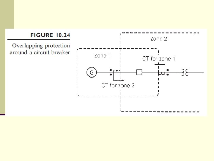
n Overlap is accomplished by having two sets of instrument transformers and relays for each circuit breaker. n For example, the breaker in Figure 10. 24 shows two CTs, one for zone 1 and one for zone 2. n Overlap is achieved by the order of the arrangement: first the equipment in the zone, second the breaker, and then the CT for that zone.
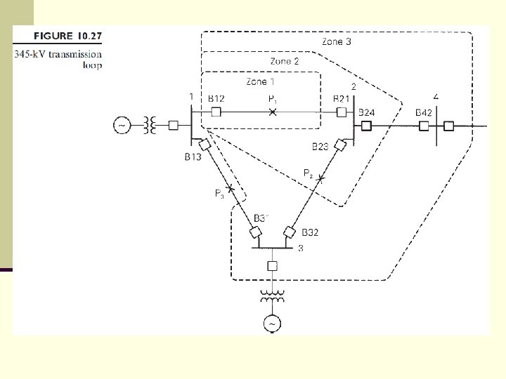
Line Protection with Impedance (Distance) Relays n Coordinating time-delay overcurrent relays can also be difficult for some radial systems. n If there are too many radial lines and buses, the time delay for the breaker closest to the source becomes excessive. n Also, directional overcurrent relays are difficult to coordinate in transmission loops with multiple sources. n Consider the use of these relays for the transmission loop shown in Figure 10. 27.
n For a fault at P 1, we want the B 21 relay to operate n n faster than the B 32 relay. For a fault at P 2, we want B 32 faster than B 13. And for a fault at P 3, we want B 13 faster than B 21. Proper coordination, which depends on the magnitudes of the fault currents, becomes a tedious process. Furthermore, when consideration is given to various lines or sources out of service, coordination becomes extremely difficult.
n To overcome these problems, relays that respond to a voltage-to-current ratio can be used. n Note that during a three-phase fault, current increases while bus voltages close to the fault decrease. n If, for example, current increases by a factor of 5 while voltage decreases by a factor of 2, then the voltage-to-current ratio decreases by a factor of 10. n That is, the voltage-to-current ratio is more sensitive to faults than current alone.
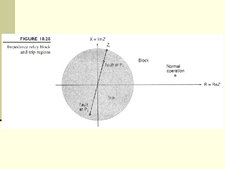
n A relay that operates on the basis of voltage-ton n current ratio is called an impedance relay. It is also called a distance relay or a ratio relay. Impedance relay block and trip regions are shown in Figure 10. 28, where the impedance Z is defined as the voltage-to-current ratio at the relay location. The relay trips for Z < Zr , where Zr is an adjustable relay setting. The impedance circle that defines the border between the block and trip regions passes through Zr.
n A straight line called the line impedance locus is shown for the impedance relay in Figure 10. 28. n This locus is a plot of positive sequence line impedances, predominantly reactive, as viewed between the relay location and various points along the line. n The relay setting Zr is a point in the R-X plane through which the impedance circle that defines the trip-block boundary must pass.
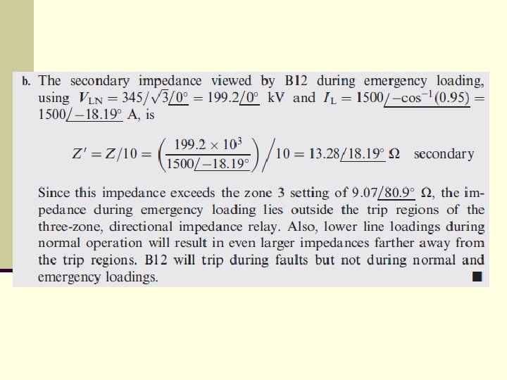
n Consider an impedance relay for breaker B 12 in Figure 10. 27, for which Z = V 1/I 12. n During normal operation, load currents are usually much smaller than fault currents, and the ratio Z has a large magnitude (and some arbitrary phase angle). n Therefore, Z will lie outside the circle of Figure 10. 28, and the relay will not trip during normal operation.
n During a three-phase fault at P 1, however, Z appears to relay B 12 to be the line impedance from the B 12 relay to the fault. n If Zr in Figure 10. 28 is set to be larger than the magnitude of this impedance, then the B 12 relay will trip. n Also, during a three-phase fault at P 3, Z appears to relay B 12 to be the negative of the line impedance from the relay to the fault. n If Zr is larger than the magnitude of this impedance, the B 12 relay will trip.
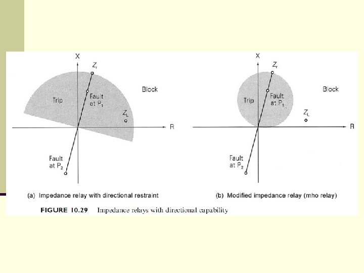
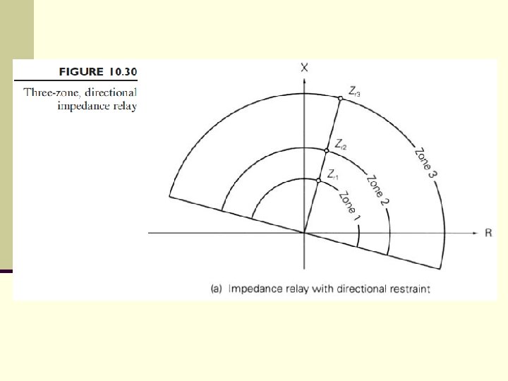
n Thus, the impedance relay of Figure 10. 28 is not directional; a fault to the left or right of the relay can cause a trip. n Two ways to include directional capability with an impedance relay are shown in Figure 10. 29. n In Figure 10. 29(a), an impedance relay with directional restraint is obtained by including a directional relay in series with an impedance relay, just as was done previously with an overcurrent relay.
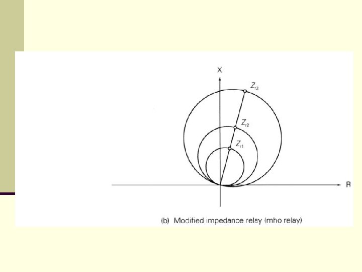
n In Figure 10. 29(b), a modified impedance relay is obtained by offsetting the center of the impedance circle from the origin. n This modified impedance relay is sometimes called an mho relay. n If either of these relays is used at B 12 in Figure 10. 27, a fault at P 1 will result in a trip decision, but a fault at P 3 will result in a block decision.
n Note that the radius of the impedance circle for the modified impedance relay is half of the corresponding radius for the impedance relay with directional restraint. n The modified impedance relay has the advantage of better selectivity for high power factor loads. n For example, the high power factor load ZL lies outside the trip region of Figure 10. 29(b) but inside the trip region of Figure 10. 29(a).
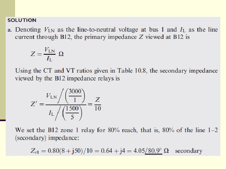
n The reach of an impedance relay denotes how far down the line the relay detects faults. n For example, an 80% reach means that the relay will detect any (solid three-phase) fault between the relay and 80% of the line length. n This explains the term distance relay.
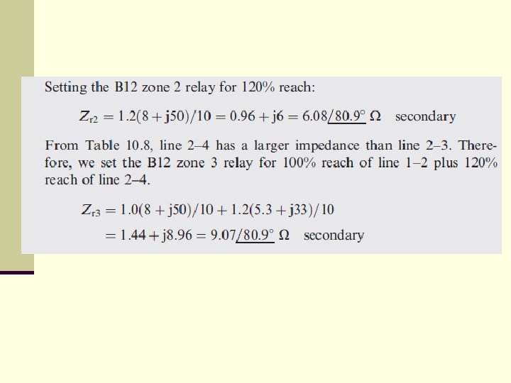
n It is common practice to use three directional impedance relays per phase, with increasing reaches and longer time delays. n For example, Figure 10. 27 shows three protection zones for B 12. n The zone 1 relay is typically set for an 80% reach and instantaneous operation, in order to provide primary protection for line 1– 2. n The zone 2 relay is set for about 120% reach, extending beyond bus 2, with a typical time delay of 0. 2 to 0. 3 seconds.
n The zone 2 relay provides backup protection for faults on line 1– 2 as well as remote backup for faults on line 2– 3 or 2– 4 in zone 2. n Note that in the case of a fault on line 2– 3 we want the B 23 relay to trip, not the B 12 relay. n Since the impedance seen by B 12 for faults near bus 2, either on line 1– 2 or line 2– 3, is essentially the same, we cannot set the B 12 zone 1 relay for 100% reach. n Instead, an 80% reach is selected to avoid instantaneous operation of B 12 for a fault on line 2– 3 near bus 2.
n For example, if there is a fault at P 2 on line 2– 3, B 23 should trip instantaneously; if it fails, B 12 will trip after time delay. n Other faults at or near bus 2 also cause tripping of the B 12 zone 2 relay after time delay. n Reach for the zone 3 B 12 relay is typically set to extend beyond buses 3 and 4 in Figure 10. 27, in order to provide remote backup for neighboring lines. n As such, the zone 3 reach is set for 100% of line 1– 2 plus 120% of either line 2– 3 or 2– 4, whichever is longer, with an even larger time delay, typically one second.
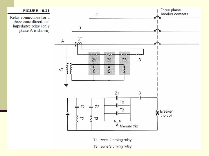
n Typical block and trip regions are shown in Figure 10. 30 for both types of three-zone, directional impedance relays. n Relay connections for a three-zone impedance relay with directional restraint are shown in Figure 10. 31.
n Remote backup protection of adjacent lines using zone 3 of an impedance relay may be ineffective. n In practice, buses have multiple lines of different lengths with sources at their remote ends. n Contributions to fault currents from the multiple lines may cause the zone 3 relay to underreach.
n The impedance relays considered so far use line-to- neutral voltages and line currents and are called ground fault relays. n They respond to three-phase, single line-to-ground, and double line-to-ground faults very effectively. n The impedance seen by the relay during unbalanced faults will generally not be the same as seen during three-phase faults and will not be truly proportional to the distance to the fault location. n However, the relay can be accurately set for any fault location after computing impedance to the fault using fault currents and voltages.
n For other fault locations farther away (or closer), the n n impedance to the fault will increase (or decrease). Ground fault relays are relatively insensitive to line-toline faults. Impedance relays that use line-to-line voltages Vab, Vbc, Vca and line-current differences Ia Ib, Ib Ic, Ic Ia are called phase relays. Phase relays respond effectively to line-to-line faults and double line-to-ground faults but are relatively insensitive to single line-to-ground faults. Therefore, both phase and ground fault relays need to be used.
Homework 4