Module 1 Principles of work key parameters of

 is a measure of how detectable an object")


, it can be used in the")


- Slides: 99
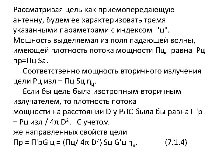
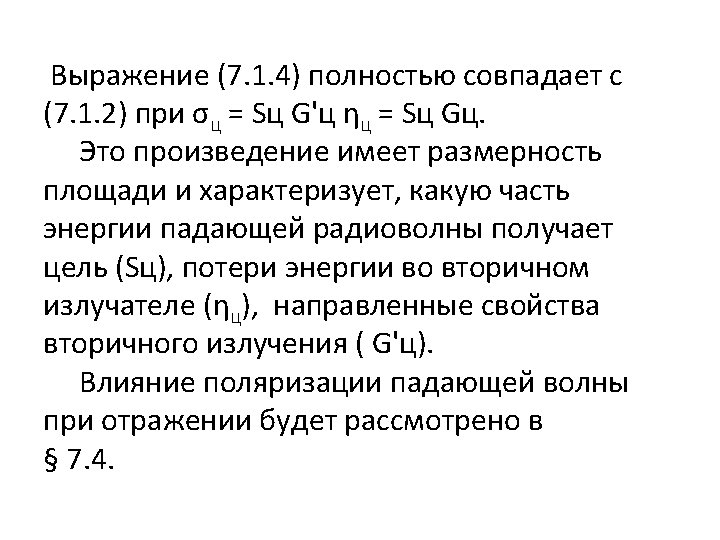
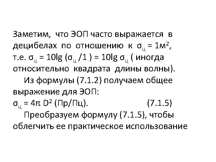
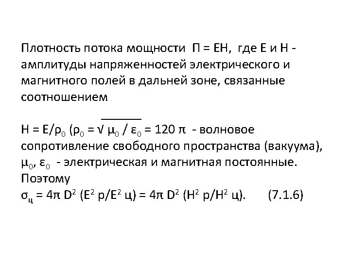
Module 1. Principles of work, key parameters of radio location systems Topic 1. 4. Secondary radiation Lecture 1. 4. 1. RECEIVERS. EFFECTIVE AREA. GROUP TARGETS
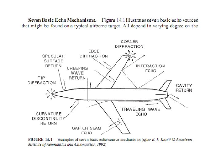
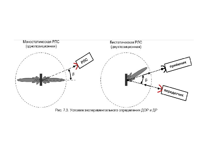
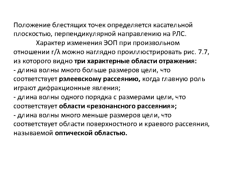
Radar cross-section Radar cross section (RCS) is a measure of how detectable an object is with a radar. A larger RCS indicates that an object is more easily detected. An object reflects a limited amount of radar energy. A number of different factors determine how much electromagnetic energy returns to the source such as: material of which the target is made; absolute size of the target; relative size of the target (in relation to the wavelength of the illuminating radar); the incident angle (angle at which the radar beam hits a particular portion of target which depends upon shape of target and its orientation to the radar source); reflected angle (angle at which the reflected beam leaves the part of the target hit, it depends upon incident angle); strength of the radar emitter; distance between emitter target receiver.
While important in detecting targets, strength of emitter and distance are not factors that affect the calculation of a RCS because the RCS is (approximately) only a property of the target. Radar cross section is used to detect planes in a wide variation of ranges. For example, a stealth aircraft (which is designed to have low detectability) will have design features that give it a low RCS (such as absorbent paint, smooth surfaces, surfaces specifically angled to reflect signal somewhere other than towards the source), as opposed to a passenger airliner that will have a high RCS (bare metal, rounded surfaces effectively guaranteed to reflect some signal back to the source, lots of bumps like the engines, antennae, &c. ). RCS is integral to the development of radar stealth technology, particularly in applications involving aircraft and ballistic missiles. RCS data for current military aircraft are almost all classified.
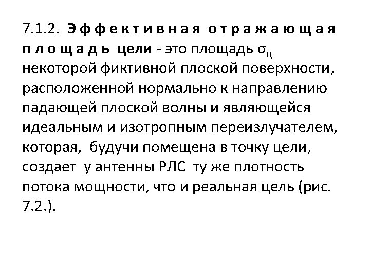
Definition Informally, the RCS of an object is the cross sectional area of a perfectly reflecting sphere that would produce the same strength reflection as would the object in question. Thus, RCS is an abstraction: The radar cross sectional area of an object does not necessarily bear a direct relationship with the physical cross sectional area of that object but depends upon other factors. Somewhat less informally, the RCS of a radar target is an effective area that intercepts the transmitted radar power and then scatters that power isotropically back to the radar receiver. More precisely, the RCS of a radar target is the hypothetical area required to intercept the transmitted power density at the target such that if the total intercepted power were re radiated isotropically, the power density actually observed at the receiver is produced.
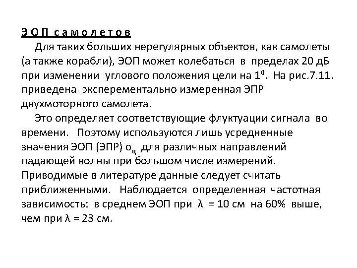
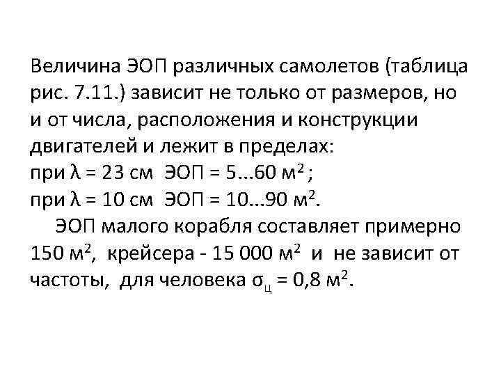
Factors that affect RCS Size As a rule, the larger an object, the stronger its Radar reflection and thus the greater its RCS. Also, Radar of one band may not even detect certain size objects. For example. 10 cm (S band Radar) can detect rain drops but not clouds whose droplets are too small. Materials such as metal are strongly radar reflective and tend to produce strong signals. Wood and cloth (such as portions of planes and balloons used to be commonly made) or plastic and fibreglass are less reflective or indeed transparent to Radar making them suitable for radomes. Even a very thin layer of metal can make an object strongly radar reflective. Also, some devices are designed to be Radar active, such as Radar antennae and this will increase RCS.
Radar absorbent paint The SR 71 Blackbird and other planes were painted with a special "iron ball paint". This consisted of small metallic coated balls. Radar energy is converted to heat rather than being reflected. Shape, directivity and orientation The surfaces of the F 117 A are designed to be flat and very angled. This has the effect that Radar will be incident at a large angle (to the normal ray) that will then bounce off at a similarly high reflected angle; it is forward scattered. The edges are sharp to prevent there being rounded surfaces. Rounded surfaces will often have some portion of the surface normal to the Radar source. As any ray incident along the normal will reflect back along the normal this will make for a strong reflected signal. Smooth surfaces The relief of a surface could contain indentations that act as corner reflectors which would increase RCS from many orientations. This could arise from open bomb bays, engine intakes, ordnance pylons, joints between constructed sections, &c. Also, it can be impractical to coat these surfaces with radar absorbent materials.
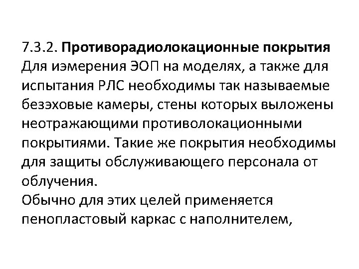
Measurement of a target's RCS is performed at a radar reflectivity range or scattering range. The first type of range is an outdoor range where the target is positioned on a specially shaped low RCS pylon some distance down range from the transmitters. Such a range eliminates the need for placing radar absorbers behind the target, however multi path interactions with the ground must be mitigated. An anechoic chamber is also commonly used. In such a room, the target is placed on a rotating pillar in the center, and the walls, floors and ceiling are covered by stacks of radar absorbing material. These absorbers prevent corruption of the measurement due to reflections. A compact range is an anechoic chamber with a reflector to simulate far field conditions.
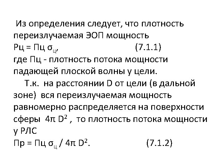
Calculation Quantitatively, RCS is calculated in three dimensions as Where σ is the RCS, Si is the incident power density measured at the target, and Ss is the scattered power density seen at a distance r away from the target. In electromagnetic analysis this is also commonly written as where Es and Ei are the far field scattered and incident electric field intensities, respectively.
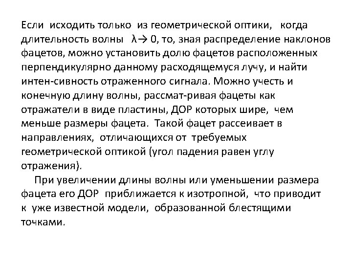
In the design phase, it is often desirable to employ a computer to predict what the RCS will look like before fabricating an actual object. Many iterations of this prediction process can be performed in a short time at low cost, whereas use of a measurement range is often time consuming, expensive and error prone. The linearity of Maxwell's equations makes RCS relatively straightforward to calculate with a variety of analytic and numerical methods, but changing levels of military interest and the need for secrecy have made the field challenging, nonetheless. The field of solving Maxwell's equations through numerical algorithms is called computational electromagnetics, and many effective analysis methods have been applied to the RCS prediction problem. RCS prediction software often run on large supercomputers and employ high resolution CAD models of real radar targets. High frequency approximations such as geometric optics, Physical Optics, the geometric theory of diffraction, the uniform theory of diffraction and the physical theory of diffraction are used when the wavelength is much shorter than the target feature size.
Statistical models include chi square, Rice, and the log normal target models. These models are used to predict likely values of the RCS given an average value, and are useful when running radar Monte Carlo simulations. Purely numerical methods such as the boundary element method (method of moments), finite difference time domain method (FDTD) and finite element methods are limited by computer performance to longer wavelengths or smaller features. Though, for simple cases, the wavelength ranges of these two types of method overlap considerably, for difficult shapes and materials or very high accuracy they are combined in various sorts of hybrid methods.
Reduction The B 2 Spirit was one of the first aircraft to successfully become 'invisible' to radar. RCS reduction is chiefly important in stealth technology for aircraft, missiles, ships, and other military vehicles. With smaller RCS, vehicles can better evade radar detection, whether it be from land based installations, guided weapons or other vehicles. Reduced signature design also improves platforms' overall survivability through the improved effectiveness of its radar counter measures. Several methods exist. The distance at which a target can be detected for a given radar configuration varies with the fourth root of its RCS. Therefore, in order to cut the detection distance to one tenth, the RCS should be reduced by a factor of 10, 000. Whilst this degree of improvement is challenging, it is often possible when influencing platforms during the concept/design stage and using experts and advanced computer code simulations to implement the control options described below.
The B 2 Spirit was one of the first aircraft to successfully become 'invisible' to radar.
Purpose shaping With purpose shaping, the shape of the target’s reflecting surfaces is designed such that they reflect energy away from the source. The aim is usually to create a “cone of silence” about the target’s direction of motion. Due to the energy reflection, this method is defeated by using Passive (multistatic) radars. Purpose shaping can be seen in the design of surfaceting on the F 117 A Nighthawk stealth fighter. This aircraft, designed in the late 1970 s though only revealed to the public in 1988, uses a multitude of flat surfaces to reflect incident radar energy away from the source. Yue suggests that limited available computing power for the design phase kept the number of surfaces to a minimum. The B 2 Spirit stealth bomber benefited from increased computing power, enabling its contoured shapes and further reduction in RCS. The F 22 Raptor and F 35 Lightning II continue the trend in purpose shaping and promise to have even smaller monostatic RCS.
Active cancellation With active cancellation, the target generates a radar signal equal in intensity but opposite in phase to the predicted reflection of an incident radar signal (similarly to noise canceling ear phones). This creates destructive interference between the reflected and generated signals, resulting in reduced RCS. To incorporate active cancellation techniques, the precise characteristics of the waveform and angle of arrival of the illuminating radar signal must be known, since they define the nature of generated energy required for cancellation. Except against simple or low frequency radar systems, the implementation of active cancellation techniques is extremely difficult due to the complex processing requirements and the difficulty of predicting the exact nature of the reflected radar signal over a broad aspect of an aircraft, missile or other target.
Radar absorbent material With radar absorbent material (RAM), it can be used in the original construction, or as an addition to highly reflective surfaces. There at least three types of RAM: resonant, non resonant magnetic and non resonant large volume. Resonant but somewhat 'lossy' materials are applied to the reflecting surfaces of the target. The thickness of the material corresponds to one quarter wavelength of the expected illuminating radar wave (a Salisbury screen). The incident radar energy is reflected from the outside and inside surfaces of the RAM to create a destructive wave interference pattern. This results in the cancellation of the reflected energy. Deviation from the expected frequency will cause losses in radar absorption, so this type of RAM is only useful against radar with a single, common, and unchanging frequency. Non resonant magnetic RAM uses ferrite particles suspended in epoxy or paint to reduce the reflectivity of the surface to incident radar waves. Because the non resonant RAM dissipates incident radar energy over a larger surface area, it usually results in a trivial increase in surface temperature, thus reducing RCS at the cost of an increase in infrared signature. A major advantage of non resonant RAM is that it can be effective over a wide range of frequencies, whereas resonant RAM is limited to a narrow range of design frequencies. Large volume RAM is usually resistive carbon loading added to fiberglass hexagonal cell aircraft structures or other non conducting components. Fins of resistive materials can also be added. Thin resistive sheets spaced by foam or aerogel may be suitable for space craft. Thin coatings made of only dielectrics and conductors have very limited absorbing bandwidth, so magnetic materials are used when weight and cost permit, either in resonant RAM or as non resonant RAM.
Radar Cross Section The experimental radar cross section of the B 26 aircraft at 3 GHz frequency as a function of azimuth angle (after Skolnik)
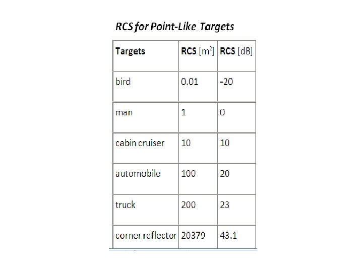
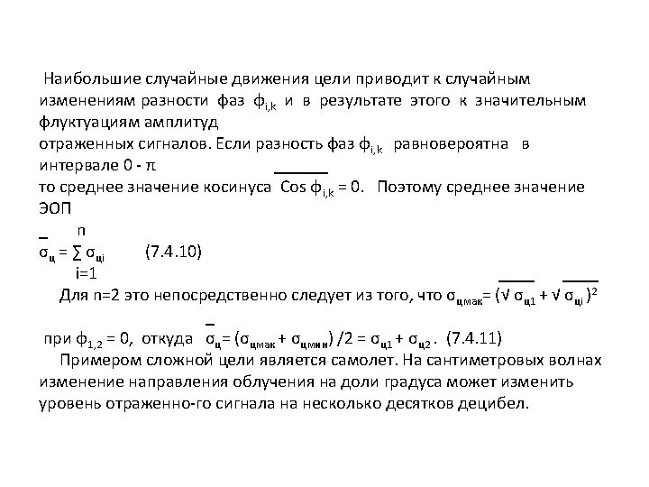
The size and ability of a target to reflect radar energy can be summarized into a single term, σ, known as the radar cross section, which has units of m². If absolutely all of the incident radar energy on the target were reflected equally in all directions, then the radar cross section would be equal to the target's cross sectional area as seen by the transmitter. In practice, some energy is absorbed and the reflected energy is not distributed equally in all directions. Therefore, the radar cross section is quite difficult to estimate and is normally determined by measurement.
The target radar cross sectional area depends of: the airplane’s physical geometry and exterior features, the direction of the illuminating radar, the radar transmitters frequency, the used material types.
The use of stealth technology to reduce radar cross section decreases the survivability and the target detection of military aircrafts. But the stealth technology depends of the used radar transmitters frequency and has none effect against VHF radars like P 12 and P 18, both used by Serbian air defense units during the Kosovo war.
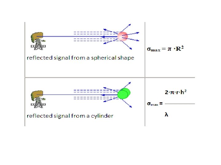
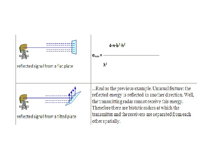
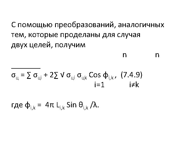
Calculation of the radar cross section The following backscattering formulas from shapes occur in an optical independent of frequency region.
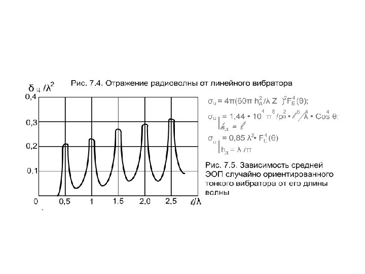
7. 2
7. 3 a
7. 4
7. 7
7. 9
7. 13
7. 10
7. 14
7. 15
END