Antenna Theory Ch 2 Fundamental Parameters of Antennas


![� Omnidirectional antenna: azimuth plane[f(Φ), θ=π/2]에 대해 nondirectional pattern을 갖고, orthogonal plane(elevation plane[g(θ), Φ=constant])에](https://slidetodoc.com/presentation_image_h/dd05b6e8526ca852c203e45812f7e884/image-8.jpg "� Omnidirectional antenna: azimuth plane[f(Φ), θ=π/2]에 대해 nondirectional pattern을 갖고, orthogonal plane(elevation plane[g(θ), Φ=constant])에")
의 성능은 안테나의 E-plane,")


- Slides: 29
Antenna Theory Ch. 2 Fundamental Parameters of Antennas 2. 1 -2. 6
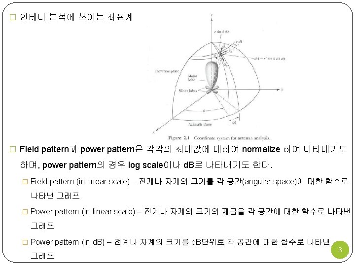
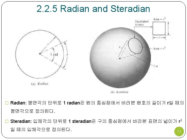
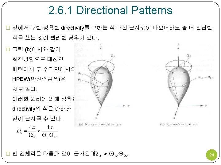
2. 2. 1 Radiation Pattern Lobes � Radiation pattern은 lobe라 불리우는 부분으로 나눌 수 있다 – major or main, minor, side, back. � Radiation lobe: radiation pattern 중 방사세기가 상대적으로 약한 부분에 둘러싸여 있 는 부분. 4
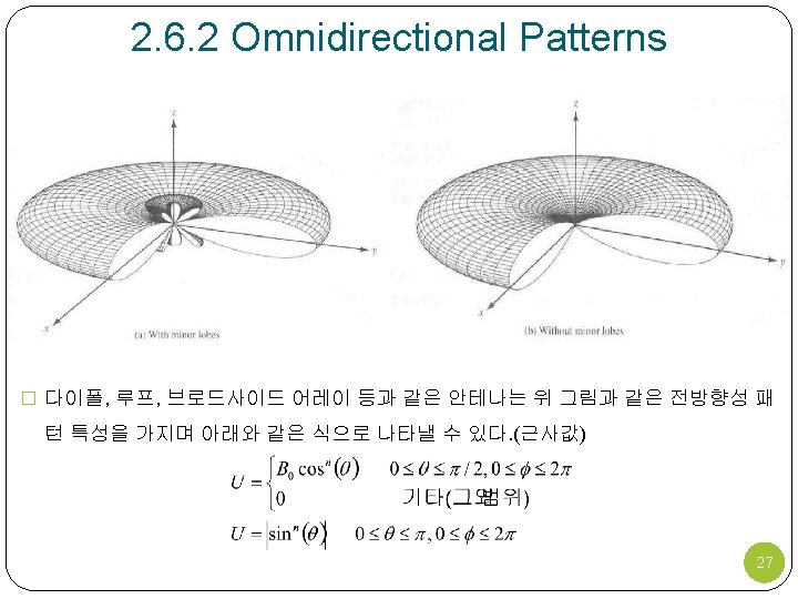
� Omnidirectional antenna: azimuth plane[f(Φ), θ=π/2]에 대해 nondirectional pattern을 갖고, orthogonal plane(elevation plane[g(θ), Φ=constant])에 대해 directional pattern 을 갖는 안테나. Directional antenna의 특별 케이스. 그림 2. 6 7
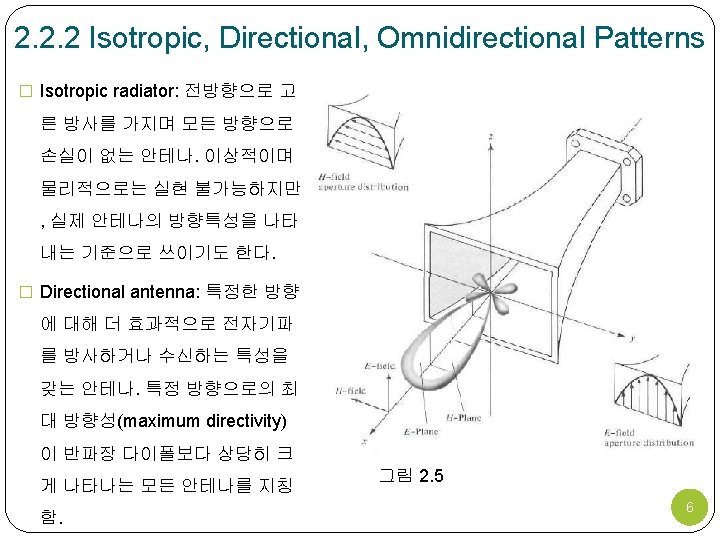
2. 2. 3 Principal Patterns � 선형 편파 안테나(linearly polarized antenna)의 성능은 안테나의 E-plane, H-plane에 의해 설명하기도 한다. � E-plane: 전계 벡터와 최대 방사의 방향을 포함하는 면 � H-plane: 자계 벡터와 최대 방사의 방향을 포함하는 면 � 그림 2. 5에서 x-z plane(elevation plane, Φ=0)이 E-plane이고, x-y plane(azimuth plane, θ=π/2)이 H-plane이다. � 그림 2. 6의 omnidirectional antenna는 무수히 많은 E-plane(elevation plane, Φ=Φc)를 가지며, 하나의 H-plane(azimuth plane, θ=π/2)을 가진다. 8
2. 2. 4 Field Regions � 안테나 주변의 공간은 다음의 세 구역으로 나눌 수 있다. � Reactive near-field region � Radiating near-field (Fresnel) region Reactive near-field region은 reactive field가 우세한 영역으로 안테나에 바로 근접해 있다. � Far-field (Fraunhofer) region Radiating near-field region은 radiation field가 우세한 영역으로 안테나와의 거 리에 따라 angular field distribution이 달 라지게 된다. 파장보다 안테나의 크기가 다르면 이 영역은 존재하지 않는다. Far-field region에서는 안테나와의 거리 에 대해 angular field distribution가 무관 하게 된다. 단, D는 안테나의 크기 9
� 영역에 따른 amplitude 의 변화 � Reactive near-field region – field가 거의 일정하게 퍼져있다. � Radiating near-field (Fresnel) region – lobe를 형성한다. � Far-field (Fraunhofer) region – major lobe와 몇몇의 minor lobe가 형성된다. 10
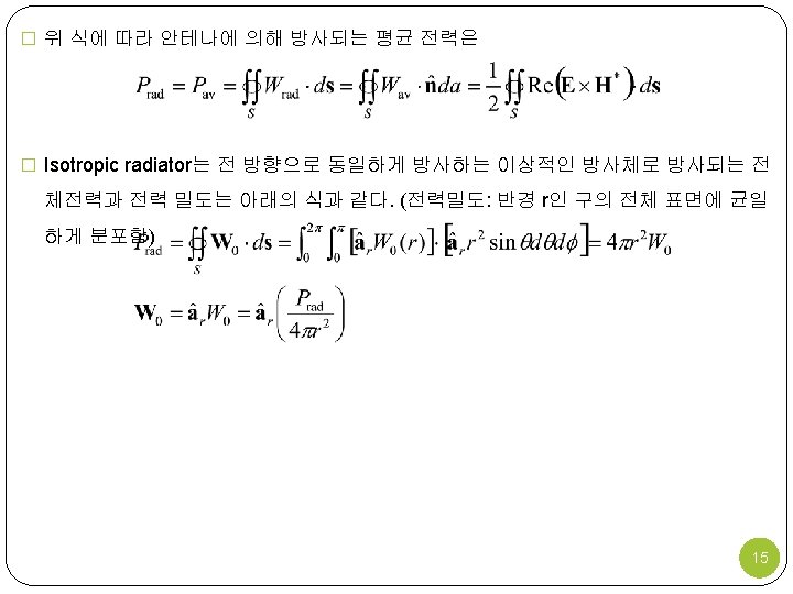
2. 3 Radiation Power Density � 전자파는 무선 매질이나 도파구조를 통해 정보를 전달하는데 사용된다. � 전자파와 관련된 전력을 나타낼 때 사용되는 양은 instantaneous Poynting vector로 아래와 같이 정의된다. � W = instantaneous Poynting vector (W/m 2) � E = instantaneous electric-field intensity (V/m) � H = instantaneous magnetic-field intensity (A/m) � 포인팅 벡터는 전력밀도이기 때문에 폐곡면을 지나는 total power는 포인팅 벡터의 수직 성분을 전체 표면에 대해 적분하여 구할 수 있다. � P = instantaneous total power (W) � = unit vector normal to the surface � da = infinitesimal area of the closed surface (m 2) 13
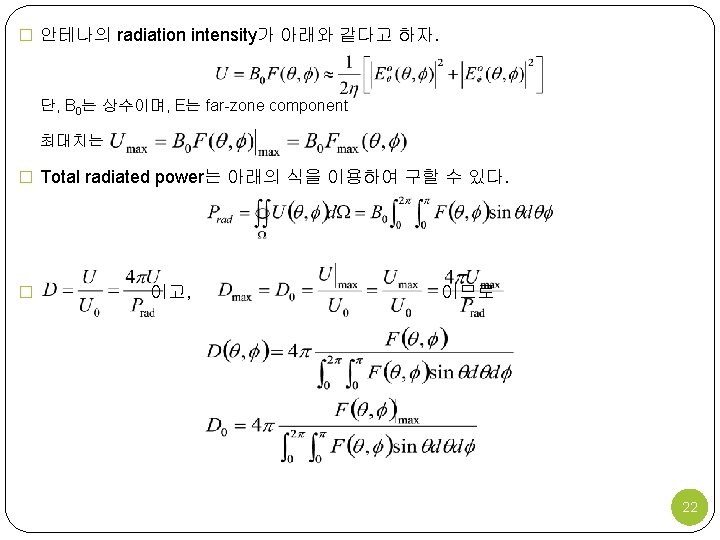
2. 4 Radiation Intensity � 주어진 방향에서의 방사 세기는 안테나의 단위 입체각으로부터 방사되는 전력으로 정의된다. 이는 far-field 파라미터이며, radiation density와 거리의 제곱의 곱으로 나 타낼 수 있다. � U = radiation intensity (W/unit solid angle) � Wrad = radiation density (W/m 2) � Radiation intensity는 안테나의 far-field region 전계와 아래와 같은 관계를 갖는다. � E(r, θ, Φ) = far-zone electric-field intensity of the antenna = � Eθ, EΦ = far-zone electric-field components of the antenna � η = intrinsic impedance of the medium 16
� 전체 전력은 radiation intensity를 전체 입체각 4π에 걸쳐 적분하여 구할 수 있다. � Isotropic source U에 대한 radiation intensity는 radiation power density와 마찬가지로 θ, Φ에 대해 무관하다. � Isotropic source에 대한 radiation intensity는 17
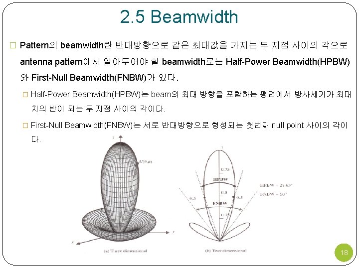
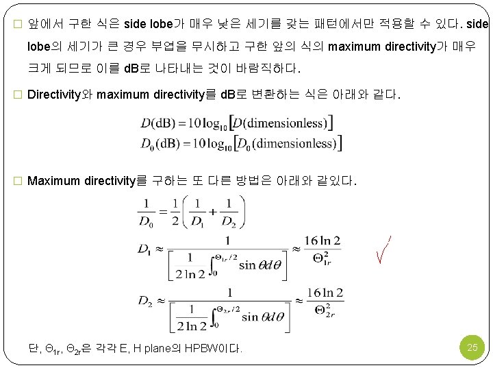
� 안테나의 beamwidth는 중요한 지표로서 side lobe level과 beamwidth는 trade-off로 사용되기도 한다 – beamwidth가 감소하면 side lobe level이 증가 하고 beamwidth가 증가하면 side lobe level이 감소하게 된다. 19
2. 6 Directivity � Directivity란 모든 방향에 걸친 average radiation intensity에 대한 주어진 방향으로의 radiation intensity의 비로 아래의 식과 같이 나타낸다. � 방향이 주어져 있지 않다면 이는 최대 방사세기의 방향을 의미하며 다음과 같은 식으 로 나타낼 수 있다. � D = Directivity (dimensionless) � D 0 = maximum directivity (dimensionless) � U = radiation intensity (W/unit solid angle) � Umax = maximum radiation intensity (W/unit solid angle) � U 0 = radiation intensity of isotropic source (W/unit solid angle) � Prad = total radiated power (W) � Isotropic source에 대해 U, Umax, U 0가 모두 동일하므로 directivity은 1이 된다. 20
� 직교 편파 성분을 갖는 안테나에 대해 주어진 방향에서 주어진 편파에 대한 안테나의 부분적인 지향성(partial directivity of an antenna for a given polarization in a given direction)은 주어진 편파에 대한 radiation intensity를 전체 방향에 걸쳐 평균한 total radiation intensity로 나눈 값으로 정의한다. � Partial directivity에 대한 정의로부터, 주어진 방향에서의 total directivity는 두 직교편 파에 대한 partial directivity의 합이다. 구좌표계에서 안테나의 직교하는 θ, Φ성분에 대한 total directivity는 다음과 같이 쓸 수 있다. � Uθ = radiation intensity in a given direction contained in θ field component � UΦ = radiation intensity in a given direction contained in Φ field component � (Prad)θ = radiated power in all directions contained in θ field component � (Prad)Φ = radiated power in all directions contained in Φ field component 21
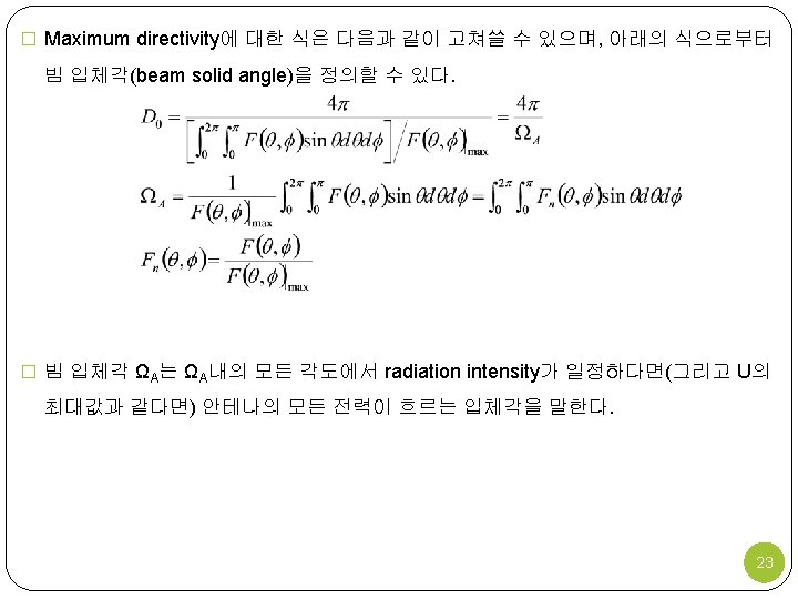
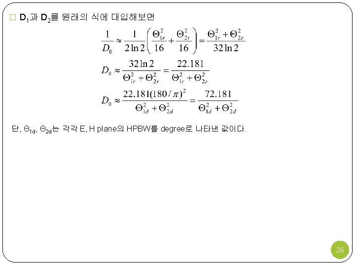
� Omnidirectional pattern에 대한 근사 directivity 공식은 � Minor lobe가 있는 경우 � Minor lobe가 없는 경우 28