Module 1 Principles of work key parameters of


 of a radar target is the angle")


 to be")


 Radar pulse relationships")
 of the radar system is the number of pulses")


 power level")
/PRT (Τ) = Duty Cycle")

 and pulse-repetition frequency (prf) in the")


- Slides: 59
Module 1. Principles of work, key parameters of radio location systems Topic 1. 2. Principles of work and key parameters of active radars Lecture 1. 2. 1. RADAR BASIC PRINCIPLES
Direction determination The direction to the target is determined by the directivity of the antenna. Directivity, sometimes known as the directive gain, is the ability of the antenna to concentrate the transmitted energy in a particular direction. An antenna with high directivity is also called a directive antenna. By measuring the direction in which the antenna is pointing when the echo is received, both the azimuth and elevation angles from the radar to the object or target can be determined. The accuracy of angular measurement is determined by the directivity, which is a function of the size of the antenna.
True Bearing
Radar units usually work with very high frequencies. Reasons for this are: - Quasi-optically propagation of these waves. - High resolution (the smaller the wavelength, the smaller the objects the radar is able to detect). - Higher the frequency, smaller the antenna size at the same gain.
The True Bearing (referenced to true north) of a radar target is the angle between true north and a line pointed directly at the target. This angle is measured in the horizontal plane and in a clockwise direction from true north. The bearing angle to the radar target may also be measured in a clockwise direction from the centerline of your own ship or aircraft and is referred to as the relative bearing.
Variation of echo signal strength
The antennas of most radar systems are designed to radiate energy in a one-directional lobe or beam that can be moved in bearing simply by moving the antenna. As you can see in the Figure 2, the shape of the beam is such that the echo signal strength varies in amplitude as the antenna beam moves across the target. In actual practice, search radar antennas move continuously; the point of maximum echo, determined by the detection circuitry or visually by the operator, is when the beam points direct at the target. Weapons-control and guidance radar systems are positioned to the point of maximum signal return and maintained at that position either manually or by automatic tracking circuits.
In order to have an exact determination of the bearing angle, a survey of the north direction is necessary. Therefore, older radar sets must expensively be surveyed either with a compass or with help of known trigonometrically points. More modern radar sets take on this task and with help of the GPS satellites determine the northdirection independently.
Transfer of Bearing Information The rapid and accurate transmission of the bearing information between the turntable with the mounted antenna and the scopes can be carried out for • servo systems and • counting of azimuth change pulses.
Servo systems are used in older radar antennas and missile launchers and works with help of devices like synchro torque transmitters and synchro torque receivers. In newer radar units we find a system of Azimuth-Change-Pulses (ACP). In every rotation of the antenna coder sends many pulses, these are then counted in the scopes. Newer radar units work completely without or with a partial mechanical motion. These radars employ electronic phase scanning in bearing and/or in elevation (phased-array-antenna).
Elevation Angle Altitude- or height-finding search radars use a very narrow beam in the vertical plane. The beam is mechanically or electronically scanned in elevation to pinpoint targets. Height-finding radar systems that also determine bearing must have a narrow beam in the horizontal plane in addition to the one in the vertical plane.
Definition of elevation angle
The elevation angle is the angle between the horizontal plane and the line of sight, measured in the vertical plane. The Greek letter Epsilon (ε) describes the elevation angle. The elevation angle is positive above the horizon (0° elevation angle), but negative below the horizon.
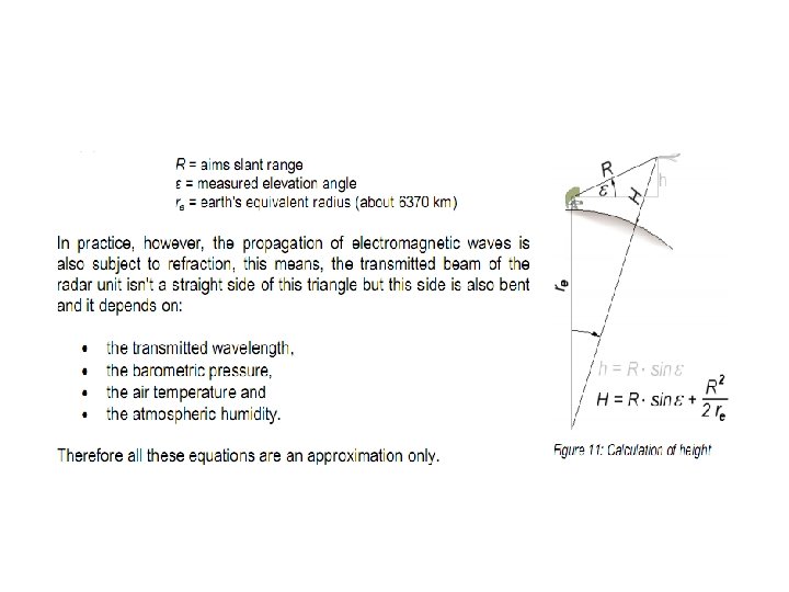
Calculation of Height Simple triangular relation between elevation and height
The height of a target over the earth's surface is called height or altitude. This is denominated by the letter H (like: Height) in the following formulae and figures. The altitude can be calculated with the values of distance R and elevation angle ε. H = R · sin ε
Altitude vs. Height
The altitude cannot be so simply calculated on a flying airplane, while refraction is caused when electromagnetic waves cross airlayers at different density and the earth's surface has a bend. The calculation of the targets altitude is not only a trigonometrically calculation. The current location grounding bend must also be taken into consideration. Both factors are compensated for with an integrated altitude calculation by extensive formulae.
One can take the mathematical rule for the calculation from Figure 2. A triangle arises between the points: center of the earth, the radar site and the position of the aircraft. The sides of this triangle are described by the cosine theorem and therefore by the equation: R 2 = re 2 + (re + H)2 - 2 re(re + H) · cos α
Under the assumption that the earth is a sphere, the section of the circumference of the earth can be calculated with help of a simple ratio from the complete circumference of the earth from the angle α: 360° · Rtopogr. = α · 2π re
This segment of the circumference of the earth can be considered an approximation of the actual topographical range (here though still without considering refraction). Example given: The measured slant range is 30 km (20 NM), the altitude is 1000 m (3000 ft) and the earth radius is 6370 km. Then the calculated difference between the slant range and the topographical range is -19 m!
In practice, however, the propagation of electromagnetic waves is also subject to a refraction, this means, the transmitted beam of the radar unit isn't a straight side of this triangle but this side is also bent and it depends on: - the transmitted wavelength, - the barometric pressure, - the air temperature and - the atmospheric humidity.
The earth radius can be multiplied with a factor for an approximation of the influence of the refraction. An equivalent earth radius of 4/3 ·re≈ 8500 km is often used and can additionally modified by a manual input of a correction factor to consider temporarily changed weather conditions or changed barometric pressure.
E. G. the following equation is used to calculate the height into the height finder PRW-16
meaning at this: 1. height without including the earth's radius 2. term including the earth's equivalent radius (about 8500 km) 3. term including the refraction into the atmosphere 4. term including the refraction’s temperature
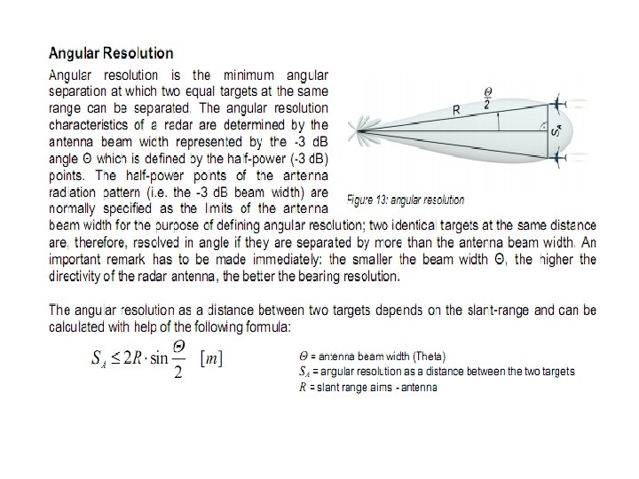
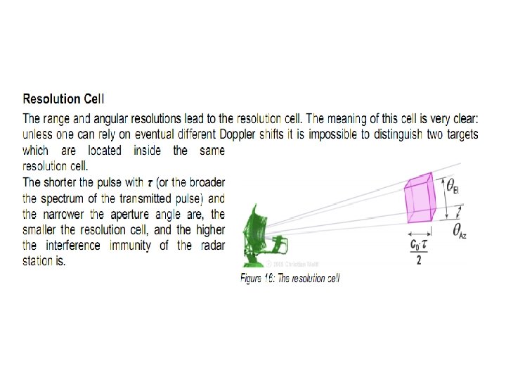
Radar Resolution The target resolution of radar is its ability to distinguish between targets that are very close in either range or bearing. Weapons-control radar, which requires great precision, should be able to distinguish between targets that are only yards apart. Search radar is usually less precise and only distinguishes between targets that are hundreds of yards or even miles apart. Radar resolution is usually divided into two categories; range resolution and angular (bearing) resolution.
Range Resolution
The target resolution of a radar is its ability to distinguish between targets that are very close in either range or bearing. Weapons-control radar, which requires great precision, should be able to distinguish between targets that are only yards apart. Search radar is usually less precise and only distinguishes between targets that are hundreds of yards or even miles apart. Resolution is usually divided into two categories; range resolution and bearing resolution.
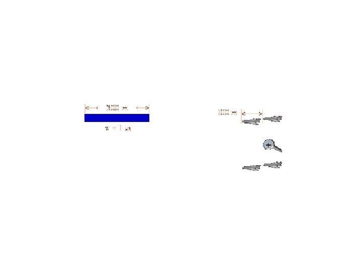
Range resolution is the ability of a radar system to distinguish between two or more targets on the same bearing but at different ranges. The degree of range resolution depends on the width of the transmitted pulse, the types and sizes of targets, and the efficiency of the receiver and indicator. Pulse width is the primary factor in range resolution. A well-designed radar system, with all other factors at maximum efficiency, should be able to distinguish targets separated by onehalf the pulse width time τ. Therefore, theoretical range resolution cell of a radar system can be calculated from the following equation: Sr ≥ c 0 · τ/2
One target includes two aims
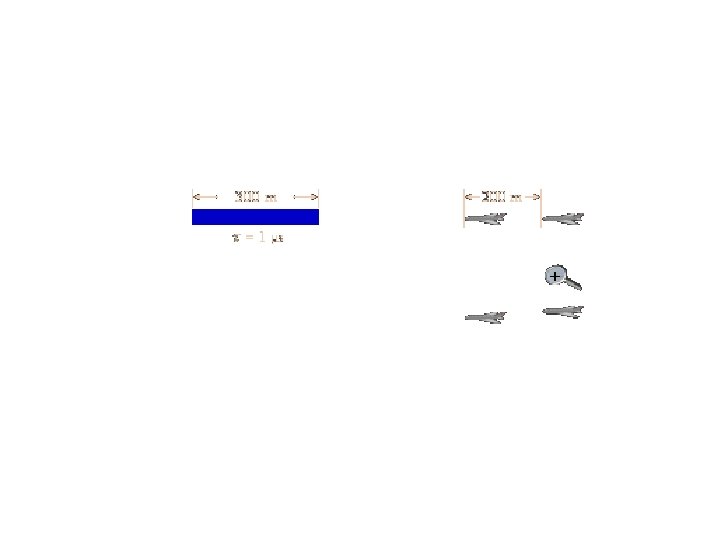
And now the other example when the spacing is large enough Two aims and two targets :
Resolution with 3 -d. B Receiver Bandwidth
Radar using Intrapulse-Modulation In a pulse compression system, the rangeresolution of the radar is given by the length of the pulse at the output-jack of the pulse compressing stage. The ability to compress the pulse depends on the bandwidth of the transmitted pulse (BWtx) (not by its pulse width). As a matter of course the receiver needs at least the same bandwidth to process the whole spectrum of the echoes. Sr ≥ c 0/2 · BWtx
This allows very high resolution (and a small radar range resolution cell) to be obtained with long pulses, thus with a higher average power. Figure 4 shows the variation of slant range resolution with bandwidth. A 1. 5 m resolution will theoretically be achieved with a -3 d. B bandwidth of 100 MHz.
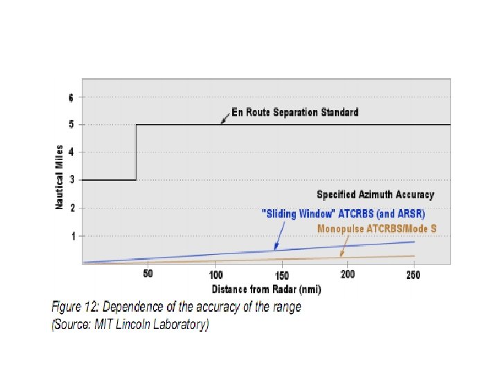
Radars Accuracy is the degree of conformance between the estimated or measured position and/or the velocity of a platform at a given time and its true position or velocity. Accuracy should not be confused with radar resolution. Radio navigation performance accuracy is usually presented as a statistical measure of system error and is specified as:
1. Predictable: The accuracy of a position in relation to the geographic or geodetic coordinates of the earth. 2. Repeatable: The accuracy in which a user can return to a position whose co-ordinates have been measured at a previous time with the same navigation system. 3. Relative: The accuracy which a user can determine one position relative to another (by neglecting all possible errors).
Some results of radar units are indicated in the following table as example:
The stated value of required accuracy represents the uncertainty of the reported value with respect to the true value and indicates the interval in which the true value lies with a stated probability. The recommended probability level is 95 per cent, which corresponds to 2 standard deviations of the mean for a normal (Gaussian) distribution of the variable. The assumption that all known correction are taken into account implies that the errors in the reported values will have a mean value (or bias) close to zero.
Any residual bias should be small compared with the stated accuracy requirement. The true value is that value which, under operational conditions, characterizes perfectly the variable to be measured/observed over the representative time, area and/or volume interval required, taking into account siting and exposure. Accuracy should not be confused with resolution.
Pulse Repetition Frequency (PRF) Radar pulse relationships
The Pulse Repetition Frequency (PRF) of the radar system is the number of pulses that are transmitted per second. Radar systems radiate each pulse at the carrier frequency during transmit time (or Pulse Width PW), wait for returning echoes during listening or rest time, and then radiate the next pulse, as shown in the figure. The time between the beginning of one pulse and the start of the next pulse is called pulse-repetition time (PRT) and is equal to the reciprocal of prf as follows: PRT = 1/PRF
The radar system pulse repetition frequency determines its ability to unambiguously measure target range and range rate in a single coherent processing interval as well as determining the inherent clutter rejection capabilities of the radar system. In order to obtain an unambiguous measurement of target range, the interval between radar pulses must be greater than the time required for a single pulse to propagate to a target at a given range and back.
The maximum unambiguous range is then given by Runamb. = c 0 /2 · PRF = c 0 · PRT/2 , where c 0 is the velocity of electromagnetic propagation.
Peak- and Average Power Duty cycle, peak- and average power
The energy content of a continuous-wave radar transmission may be easily figured because the transmitter operates continuously. However, pulsed radar transmitters are switched on and off to provide range timing information with each pulse. The amount of energy in this waveform is important because maximum range is directly related to transmitter output power. The more energy the radar system transmits, the greater the target detection range will be.
The energy content of the pulse is equal to the peak (maximum) power level of the pulse multiplied by the pulse width. However, meters used to measure power in a radar system do so over a period of time that is longer than the pulse width. For this reason, pulse-repetition time is included in the power calculations for transmitters. Power measured over such a period of time is referred to as average power.
Paverage / Ppeak = Pulse Width (τ)/PRT (Τ) = Duty Cycle
Peak power must be calculated more often than average power. This is because most measurement instruments measure average power directly. Transposing the upper equation gives us a common way for calculating peak power/average power. Since the storage of the energy in the modulator, the power supply must make plant for the transmitter available a little more than the average power only.
Duty cycle The product of pulse width (pw) and pulse-repetition frequency (prf) in the above formula is called the duty cycle of a radar system. Duty cycle is the fraction of time that a system is in an “active” state. In particular, it is used in the following contexts: Duty cycle is the proportion of time during which a component, device, or system is operated. Suppose a transmitter operates for 1 microsecond, and is shut off for 99 microseconds, then is run for 1 microsecond again, and so on. The transmitter runs for one out of 100 microseconds, or 1/100 of the time, and its duty cycle is therefore 1/100, or 1 percent. The duty cycle is used to calculate both the peak power and average power of a radar system.
Dwell Time and Hits per Scan Most processes in pulse radar are time-dependent. So there are some terms established to describe this time dependence The target on the screen is a result of hits
Dwell Time The time that an antenna beam spends on a target is called dwell time TD. The dwell time of a 2 D–search radar depends predominantly on - the antennas horizontally beam width ΘAZ and - the turn speed n of the antenna (rotations per minute).
The dwell time can be calculated using the following equation: TD = ΘAZ · 60/ 360° · n ; in [seconds]
Hits per Scan The value of hits per scan m says how many echo signals per single target during every antenna swing are received. The hit number stands e. g. for a search radar with a rotating antenna for the number of the received echo pulses of a single target per antenna turn. The dwell time TD and the pulse repetition time PRT determine the value of hits per scan. m = TD /PRT = ΘAZ · 60/ 360° · n · PRT
So that radar equipment can evaluate the target information with sufficient precision, hit numbers are between 1 and 20 as necessary, which depends on the radar set operating mode.