Micro Trend Automation Ltd Programmable 4 Axis Controller

Micro Trend Automation Ltd. Programmable 4 -Axis Controller UTC® Series

UTC 400 P 4 -Axis Motion Controller

Block Diagram SRAM 128 K*32 FLASH 512 K*8 Com 1 2 3 2 Com 2 2 3 2 JHW ENC Encoder Interface JDI Digit In Port JDO Digit Out Port JAI Analog Input LED JAO Analog Port MIO Port 1 6 C 5 5 2 Pulse/Direction TMS 320 C 32 Data Address FPGA Pulse/Voltage DAC Command Driver 1. . 4 Line Receiver Encoder Feedback A, /A, B/B, Z, /Z Pulse/Direction DAC Expan Port CN 1 JACC LCM Port CN 2 JDSP DIP Switch CN 3 JTHW

UTC 400 P-PACK LAYOUT

UTC 400 P is a multifunctional general-purpose programmable motion controller; use the most advanced 32 -bit floating-point DSP and special FPGA as its kernel. n n Glue Dispensing Machine Sealing Machine n Milling Machine/Engraving Machine Lathe Machine Application Field n Laser Cutter Brush Maker n Wood Cutting Machine Bar Feeder n Stamping Machine Fly Cutter/Fly Shear n Grinding Machine Printing Machine n Press Feeder Gilding Machine n Folding and Gluing Machine PC Board Maker n Steel Cutting Machine Packing Machine n Winding Machine Rotary Table n Foam Cutting Machine Drilling Machine n Injection Molding Machine Electronic Machine n Spring Coiling Machine n n n

UTC 400 P Multi-Tasking Executes Motion Program w UTC 400 P executes one move at a time, performing all calculations up to that move w UTC 400 P is always working ahead to blend into the upcoming move w UTC 400 P also has Spline Move capability Executes PLC Program w Continuously scan PLC’s as fast as processor time allows w PLC’s are useful for any task that is asynchronous to the motion
 General Housekeeping w Watch Dog Timer w Hardware Overtravel")
UTC 400 P Multi-Tasking (continued) General Housekeeping w Watch Dog Timer w Hardware Overtravel Limits w Software Overtravel Limits w Amplifier Faults Communicates with the host computer w UTC 400 P can communicate with the host at any time, and response to any request by host. w If the command is illegal, it will report an error to the host

UTC 400 P Interface n LCD Module l l n UT 740 / UT 725 Panel l n Standard LCD Module (40 x 2 or 20 x 4) PLC Programmable Display Parameters Setting Manual / Auto Mode Basic Function Keys PLC Man-Machine Interface l l User Defined Operation Panel User Defined Function Key Integer , Floating-Point Mathematics Macro Definition

UT-750 UT-747 UT-740 UT-725 UT-735

UTC 400 P PC User Interface UTCSetup® Provides a windows-based operation environment that can easily connect to UTC 400 P. In this program, the users can : n n n Issue any online commands to UTC 400 P Upload / Download motion programs and PLC programs Monitor motors’ position, I/O, and system status Setup motors and system parameters Backup card configuration


UTC 400 P Classic System Configuration Hardware System Wiring Safety Verification Parameter M-Variable Definition (SETUP. UTC) Coordinate System Definition Program User Interface, Motion Program, PLC Program Coding and Debug

UTC 400 P Commands 1. Online Commands A. Global Commands B. Coordinate Commands (&n …) C. Motor Commands (#n…) Modal Setting, Motor Jogging, Get Position, Set Variable Value, Buffer Control…etc. 2. Buffered Commands A. Motion Program Motor Move, Interpolation, Computation, Logic Control, Online Commands, Send Messages. B. PLC Program Computation, Logic Control, Online Commands, Send Messages.

UTC 400 P Variables 1. I-Variables w Initialization and Setup w I 0~I 99: Global System Setup w Ix 01~Ix 49: Motor Parameter Setup w Ix 50~Ix 70: Coordinate System Setup w Ix 80~Ix 89: Encoder Setup 2. P-Variables (1024) w General-purpose use w 32 -bit floating point format w Usable by all programs and coordinate systems
 3. Q-Variables (1024) w General-purpose use w 32 -bit")
UTC 400 P Variables (continue) 3. Q-Variables (1024) w General-purpose use w 32 -bit floating point format w Coordinate system specific 4. M-Variables (1024) w Pointers to registers, I/O, A/D, D/A…etc. w Can specify start bit and width w Ssigned integer, unsigned integer or floating point format

System I-Variables I 0 I 1 I 2 I 3 I 4 I 5 I 6 I 9 I 10 I 18 I 19 Card Number Coordinate System Activation Control COM 2 Baudrate Control COM 2 Handshake Control Wait State Control Position/Velocity Response Control PLC Programs On/Off Control Maximum Digit for Floating Point Returned Real Time Interrupt Period Extension I/O Board Enable Digital Inputs Debounce Cycle
 ) Ix 00 Ix 01 Ix")
Motor I-Variables (x = motor number (1~ 4) ) Ix 00 Ix 01 Ix 02 Ix 03 Ix 05 Ix 06 Ix 07 Ix 08 Motor x Activate Control Motor x Jog / Home Acceleration Time Motor x Jog / Home S-Curve Time Motor x Jog Speed Motor x Master Following Enable Motor x Master Scale Factor Motor x Homing Speed and Direction Motor x Home Offset
5 4 0 010101000000 = 0 DAC")
Ix 09 – Motor x Flag Control Hex($)5 4 0 010101000000 = 0 DAC or Pulse Command Not Converted = 1 DAC or Pulse Command Converted = 0 Jog Affected by Feedrate Override = 1 Jog Not Affected by Feedrate Override = 0 Keep Current Position on Power Up = 1 Reset Current Position on Power Up = 0 Servo Disable on Power Up = 1 Servo Enable on Power Up = 0 Driver Fault is High True (Normally Close) = 1 Driver Fault is Low True (Normally Open) = 0 Driver Fault Enable = 1 Driver Fault Disable = 0 Driver Enable is Low True = 1 Driver Enable is High True = 0 Servo Enable Deactivate(Can be used as DOUT) = 1 Servo Enable Activate = 0 Limit Switch is High True (use B-type switch) = 1 Limit Switch is Low True (use A-type switch) = 0 Hardware Limit Enable = 1 Hardware Limit Disable = 0 Reset Motor Position After Home Complete = 1 Keep Motor Position After Home Complete = 0 Home Move Allowed = 1 Home Move not Allowed
 Ix 10 Ix 11 Ix 12 Ix 13 Ix 14 Ix")
Motor I-Variables (continue) Ix 10 Ix 11 Ix 12 Ix 13 Ix 14 Ix 15 Ix 16 Ix 17 Ix 19 Ix 20 Ix 21 Ix 22 Motor x Positive Software Limit Motor x Negative Software Limit Motor x Coordinate Position Displacement Motor x Coordinate Position Scaling Motor x Coordinate Unit Scaling Motor x Backlash Size Motor x Backlash Takeup Rate Motor x Rollover Range Motor x Velocity Weighting Motor x Proportional Gain (Kp) Motor x Derivative Gain (Kd) Motor x Velocity Feedforward Gain (Kvff)

Ix 23 Ix 24 Ix 25 Ix 26 Ix 27 Ix 28 Ix 29 Ix 30 Ix 31 Ix 32 Ix 33 Ix 34 Ix 35 Motor x Integral Gain (Ki) Motor x Integration Mode Motor x Acceleration Feedforward Gain Motor x Position Feedback Address Motor x Velocity Feedback Scale Motor x DAC Bias Motor x DAC Limit Motor x Fatal Following Error Motor x Dead Band Size Motor x In Position Band Motor x Big Step Size Motor x Integration Limit
 ) Ix 50 Ix")
C. S. I-Variables (x = c. s. number (1~ 4) ) Ix 50 Ix 51 Ix 52 Ix 53 Ix 54 Ix 55 Ix 56 Ix 57 Ix 58 Ix 59 Ix 60 Ix 61 Blended Move Enable Control Maximum Permitted Acceleration Default Program Acceleration Time Default Program S-Curve Time Default Program Feedrate Time Base Slew Rate Rapid Move Feedrate Rapid Move Acceleration Time Acceleration Mode Rotate Angle External Time Base Scale External Time Base Source
 ) Ix 80 Ix 81 Ix")
Encoder I-Variables (x = encoder ch. (1~ 4) ) Ix 80 Ix 81 Ix 82 Ix 83 Ix 84 Ix 85 Ix 86 Encoder x Decode Control Encoder x Capture Flag Control <Reserved> Master x Source Address Master x Moving Average Buffer Size

Motor Jogging Commands J+ - Jog motor in positive direction J- - Jog motor in negative direction J/ - Stop jogging motor; enable driver if disabled J= - Jog motor to variable specified position J={constant} - Jog motor to specified position J: - Jog motor variable specified distance J: {constant} - Jog motor specified distance J* - Jog motor to last programmed position Jog speed is determined by Ix 03, a change in this parameter will not effect until the next jog command issued.

Motor Jogging Examples #1 J+ - Motor 1 jog in positive direction #1 J=1000 #2 j+ - Motor 1 jog to count 1000 position Motor 2 jog in positive direction I 103=30 - Set jog speed of motor 1 to 30 counts / msec I 201=50 - Set jog acceleration time of motor 2 to 50 msec We cannot jog the motor defined in the coordinate system that is running a program. If we want to do this, we should issue a “S” command first to stop the motor at end of a block then jog the motor.

Home Searching Commands HM - Perform homing search move for motor HMZ - Declare current position to be home position Examples : #1 HM – Motor 1 perform a homing search #1 HM #2 HM #3 HM – Three motors perform homing search simultaneously. We cannot perform a home searching of a motor defined in the coordinate system that is running a program.
 Ix 07")
UTC 400 P Home Searching I-Variables Ix 01 Acceleration Time (unit: msec) Ix 07 Home Speed / Direction (unit: counts / sec) Ix 08 Home Offset (unit: counts) Ix 09 Flag Control

Motion Profile of Home Searching Vel Trigger Occurs Position Captured Home Complete=0 Home Search In Progress=1 Net distance from trigger position Ix 07 Output Pulse by Pulse About 2 kpps Time Ix 02 Ix 01 Home Complete=1 Ix 02 Trigger Occurs Again

Motion Profile of Home Searching Trigger Occurs FL False Offset Ix 01 Ix 07 Ix 01 Offset:Ix 18 Ix 01 Offset:−Ix 18 Offset:+Ix 18

P-Variables w General-Purpose Use w 32 -bit Floating Point Format w Global Variable (Independent with coordinate System) They are used for : 1. Calculations P 100=P 101*(sin(45)) 2. Software triggers IF(M 1!= 1 AND P 10 = 0)
 Suppose you wanted to move a motor along the position profile defined")
P-Variables (continue) Suppose you wanted to move a motor along the position profile defined by SIN(q) + COS(q). You could do one of the following: Use hard-coded and pre. OR calculated points in a program X 1. 0173 X 1. 0343. . X 0. 9824 X 1 Use an equation to generate points on the fly P 1=0 WHILE (P 1<361) P 2=SIN(P 1)+COS(P 1) X(P 2) P 1=P 1+1 ENDWHILE

Program Calculations UTC 400 P’s DSP provides you the computational power to do a tremendous amount of calculations inside your motion program OPEN PROG 1 CLEAR WHILE(1=1) IF(P 1>0) P 2=SIN(P 1)+COS(P 1) p 3=2 IF(P 1>3) P 2=SIN(P 1)+COS(P 1) P 3=2 ‧ ‧ ‧ IF(P 1>99) P 2=SIN(P 1)+COS(P 1) p 3=99 ENDIF X 2000 P 1=P 1+1 ENDWHILE CLOSE
 changes according to the")
Q-Variables Memory Allocation The physical memory accessed by typing Q(number) changes according to the currently addressed Coordinate System. &1 Q 0 &2 Q 0 accesses location $1400 $1600 &7 Q 0 &8 Q 0 accesses location $1580 $1780 This kind of addressing simplifies memory management on multiple coordinate system applications. If we have 4 coordinate systems and 4 programs that uses them, all programs can use the same number variables Q 0 to Q 255 without redundancy therefore without memory conflicts

Q-Variables Memory Map

M-Variables Used to access UTC 400 P memory and I/O points Can define any start bit and width Format can be signed integer, unsigned integer and floating point 31 30 29 28 27 26 25 24 23 22 21 20 Sign Width Start Bit Type Address- Memory address, range 0000 -FFFF Type 0: Don’t point to any address 1: Point to data area, DP = 00 2: Point to I/O area, DP = FF Start Bit- Starting bit of the word to be used, range 0 -31 Width. Number of bits of the word to be used, range -031 Sign 1: Signed integer format 0: Unsigned integer format Bit 310: The word to be used is integer 1: The word to be used is floating point
")
M-Variable Definition Mxx->* Don’t point to any address (can be used as signed integer) Mxx->addr[, start][, width][, s] Point to data area (integer) Mxx->L: addr Point to data area (32 -bit floating point) Mxx->I: addr[, start][, width][, s]Point to I/O area Mxx-> Report current M-variable definition Defining M-Variables: M 0 ->536, S Point to Interrupt Counter M 1 ->14, 16, 1 Point to Machine Output 1 M 19 ->I: FF 41, 16, 8 Point to Machine Input 1 -8 M 102 ->AA, S Point to #1 Command Velocity Using M-Variables M 1 = 0 Turn on Machine Output 1 M 9 = 45 Turn on Machine Outputs 1, 3, 4, 6 and turn off Machine Outputs 2, 5, 7, 8 45 = 00101101 binary

UTC 400 P Coordinate Systems Permitted Axis Names: X, Y, Z, U, V, W, A, B, C v Name of axis can be redundant v Scale must be any positive floating point value v Motor direction can be set by Ix 04 We can not jog the motor defined in the coordinate system that is running a program. But we can still jog the motors defined in another coordinate system that is not running program in the same time.

Defining Coordinate Systems Choose a motor and give it a axis name and scale Unit of scale: counts / user unit Suppose the encoder resolution of motor is 4000 counts per revolution, the pitch of ball screw is 5 mm : &1 #1 ->800 X #2 ->800 Y #3 ->800 Z &2 #4 ->20 X
 &1 #1 ->X &2 #2 ->X { This")
Multiple Axis Definitions (&->Coordinate; #->Motor; X->Axis) &1 #1 ->X &2 #2 ->X { This is permitted. The two motors will act as X-axes in independent coordinate systems. &1 #1 ->X #2 ->X { This is permitted. The motors will act on identical X-axis trajectories, as in a gantry system.
 &1 #1 ->X #1 ->Y &1 #1 ->X &2 #1")
Multiple Axis Definition (continue) &1 #1 ->X #1 ->Y &1 #1 ->X &2 #1 ->X { This is NOT permitted. A motor cannot perform two different motions at same time in a program. The first axis definition will be cancelled out by the second. { This is NOT permitted. A motor will receive conflicting commands while running two program. The second coordinate definition will be rejected.

Motion Programs • UTC 400 P programs u Are executed one move at a time, performing all calculations up to that move u Run in coordinate systems u One program can simultaneously run in multiple coordinate systems u One program can run in any coordinate system u A coordinate system can only run one motion program at a time
 • Starting a program u Address to the desired coordinate system")
Motion Programs (continue) • Starting a program u Address to the desired coordinate system using the on-line command: &n u Point the coordinate system to the desired program using the on-line command: Bn u Use the on-line commands: R or ^R • Stopping a program u Point to the desired coordinate system using the on-line command: &n u Use the on-line commands: S, A, or ^S, ^A, <CTRL-K>

UTC 400 P Motion Program Commands n Move Commands X 1000 Y 2000 Z 3000 U(P 1*3. 14159) V(20*SIN(Q 6)) DWELL, DELAY n Modal Commands ABS, INC, FRAX, NORMAL LIN, RPD, CIR 1, CIR 2, SPLINE TA, TS, TM, F n Variable Value Assignment {variable} = {expression}
 n Logic Control Statements N, GOTO, GOSUB,")
UTC 400 P Motion Program Commands (continue) n Logic Control Statements N, GOTO, GOSUB, CALL, RET G, M, T, (special CALL statements) IF, ELSE, ENDIF, WHILE, ENDWHILE n Miscellaneous Statements CMD, SEND, DISP ENAPLC, DISPLC

UTC 400 P Logic Operators used in Motion Programs and PLCs n Logic Operators & | ^ (bit by bit AND) (bit by bit OR) (bit by bit Exclusive OR) Comparators = != < <= > >= (equal to) (not equal to) (less than or equal to) (greater than or equal to) Functions SIN, COS, TAN, ASIN, ACOS, ATAN 2, SQRT, LN, EXP, FABS, INT, ROUND

Example 1: A Simple Move This example shows how to program a simple move on the program specifies how to do the move, then commands the move. *********** Set-up and Definitions *********** &1 CLOSE #1 ->X ; Coordinate System 1 ; Make sure all buffers are closed ; Assign motor 1 to the X-axis - 1 program unit ; of X is 1 encoder count of motor #1 *********** Motion Program Text ************* OPEN PROG 1 ; Open buffer for program entry, Program #1 CLEAR ; Erase existing contents of buffer LINEAR ; Blended linear interpolation move mode ABS ; Absolute mode - moves specified by position TA 500 ; Set 1/2 sec (500 msec) acceleration time TS 0 ; Set no S-curve acceleration time F 300000 ; Set feedrate (speed) of 300000 units(cts)/minute X 10000 ; Move X-axis to position 10000 DWELL 500; Stay in position for 1/2 sec (500 msec) X 0 ; Move X-axis to position 0 CLOSE ; Close buffer - end of program To run this program: &1 B 1 R ; Coord. System 1, point to Beginning of Program 1, Run

Example 1: A Simple Move

Linear Mode Trajectories Small Acceleration Time V TA TM or. DP/F TA time V TA TM or. DP/F time TA
 Small Acceleration Time V TA TM or. DP/F time TA")
Linear Mode Trajectories (continue) Small Acceleration Time V TA TM or. DP/F time TA V TA TA TA TM or. DP/F time
 Acceleration Time matches Move Time V time TM or. DP/F")
Linear Mode Trajectories (continue) Acceleration Time matches Move Time V time TM or. DP/F V TM or. DP/F TA time TM or. DP/F TA TA
 Acceleration Time matches Move Time V TM or. D P/F")
Linear Mode Trajectories (continue) Acceleration Time matches Move Time V TM or. D P/F TA time TM or. D P/F TA TA TA
 Large Acceleration Time V time TM or DP/F TA TA")
Linear Mode Trajectories (continue) Large Acceleration Time V time TM or DP/F TA TA V TM or DP/F TA time TM or DP/F TA TA
 Large Acceleration Time V TM or DP/F TA time TM")
Linear Mode Trajectories (continue) Large Acceleration Time V TM or DP/F TA time TM or. DP/F TA TA
 Ix 53 Program S-Curve")
Motion Acceleration I-Variables Ix 52 Program Acceleration Time (unit: msec) Ix 53 Program S-Curve Time (unit: percent) 0 > TS>100 Ts=TA*TS/2 V Ts Ts Ta T
 V TS= 100 Ts Ts 2*Ts Ts Note that TA=2")
Motion Acceleration I-Variables (continue) V TS= 100 Ts Ts 2*Ts Ts Note that TA=2 Ts Ts 2*Ts T
 TS = 0 V TA TA T")
Motion Acceleration I-Variables (continue) TS = 0 V TA TA T

ACCELERATION UTC 400 P “S” Curve Acceleration 2 a 1. 5 a a TIME 0 VELOCITY MAX. 0 Ts Ts TA TIME

Example 2: A More Complex Move This example introduces incremental and time-specification of moves, looping logic, using variables, scaling of axes, and simple arithmetic. Note that logical and mathematical operations do not delay moves. ; ********** Set-up and Definitions ********** &1 CLOSE #1 ->1000 X ; Coordinate system 1 ; Make sure all buffers are closed ; 1 unit (cm) of X is 1000 counts of motor 1 ; ********** Motion Program Text ************ OPEN PROG 2 ; Open buffer for entry, Program #2 CLEAR ; Erase existing contents of buffer LIN ; Blended linear interpolation move mode INC ; Incremental mode - moves specified by distance TA 500 ; 1/2 sec (500 msec) acceleration time TS 100 ; 1/4 sec in each half of S-curve TM 2000 ; 2 sec move time (to start of decel) P 1=0 ; Initialize a loop counter variable WHILE (P 1<10) ; Loop until condition is false (10 times) X 10 ; Move X-axis 10 cm (=10, 000 cts) positive DWELL 500 ; Hold position for 1/2 sec X-10 ; Move X-axis back 10 cm negative DWELL 500 ; Hold position for 1/2 sec P 1=P 1+1 ; Increment loop counter ENDWHILE ; End of loop CLOSE ; Close buffer - end of program To run this program: &1 B 2 R ; Coordinate System 2, point to Beginning of Program 2, Run
 Repeat 9 More Times 0")
Example 2: A More Complex Move 5000 Velocity (count/second) Repeat 9 More Times 0 -5000 0 1 2 3 4 5 6 Time (second)

UTC 400 P Blended Move UTC 400 P will blend moves together unless one of the following conditions is true: u The moves are separated by a DWELL statement u 2 backward jumps in the program are encountered before the next move statement (GOTO, ENDW) u The move blend enable is not set (Ix 50=0) Blending allowed Blending not allowed

Difference Between Blended and non-Blended Move Y Y X X Vx Vx t t Vy Vy t Non-Blended t Blended

DWELL Vs. DELAY DWELL u Always uses fixed time base u Time does not include preceding deceleration time u Next move will not be calculated until after end of DWELL Move Time TM or D P/F TA DWELL Time Calculate Time Move Time TM or D P/F
 DELAY u Uses variable time base (% value) u Time")
DWELL Vs. DELAY (continue) DELAY u Uses variable time base (% value) u Time includes preceding deceleration time u Minimum time is current TA time u Upcoming move calculated at beginning of DELAY Move Time TM or D P/F DELAY Time Move Time TM or D P/F
 X 3 Y 4 F 10 INC")
Vector Feedrate Axes INC FRAX (X, Y) X 3 Y 4 F 10 INC FRAX (X, Y) X 3 Y 4 Z 12 F 10
 INC FRAX (X, Y, Z) X 3 Y 4 Z")
Vector Feedrate Axes (continue) INC FRAX (X, Y, Z) X 3 Y 4 Z 12 F 10 INC FRAX (X, Y) C 10 F 10

Vector Direction of Circular Interpolation +Z G 17 +Z CW CW +X +Y +X NORMAL K-1 +Y NORMAL K 1 +Z +Z CW G 18 +X +Y +X CW +Y NORMAL J-1 NORMAL J 1 +Z +Z CW G 19 +X +Y NORMAL I-1 +X CW NORMAL I 1 +Y
 Y Y Defaults NORMAL K-1 ABS")
UTC 400 P Circular Interpolation END (25, 30) Y Y Defaults NORMAL K-1 ABS (X, Y) CIR 1 F 10 X 25 Y 30 I 20 J 5 Y CENTER (15, 20) START (25, 20) I CENTER (30, 10) START (10, 5) J END (15, 10) I Y X Y CIR 1 F 25 X 30 Y 10 I-10 J 10 or I-10 J 10 Y X X X CIR 2 TM 2000 X 0 Y 10 R 10 END (0, 10) CIR 2 TM 2000 X 0 Y 10 R-10 CENTER (20, 20) J CIR 2 TM 1000 X 15 Y 10 I-10 I Y START, END (30, 10) X X START (10, 0) X

Blended Between Linear and Circular Line / Arc / Arc Non-Tangent

Profile of Circular Interpolation Vprof 1 Y Q 2 X t VQ 2 Vy p Vx 2 p Q 1 1 2 Vx (t) = Vx ( Q ) Vprof (t) = R (-sin Q ) Vprof (t) Vy (t) = Vy ( Q ) Vprof (t) = Rcos Q Vprof (t)

Example of circular interpolation 16 ; Setup and definitions &1 #1 ->10000 x #2 ->10000 y 14 ; Motion Program Text 12 open prog 4 clear rpd x 1 y 4 f 5 lin y 13 cir 1 x 2 y 14 i 1 j 0 lin x 3 cir 1 x 4 y 13 i 0 j-1 lin y 7 cir 2 x 7 y 4 i 3 j 0 lin x 13 cir 1 x 14 y 3 i 0 j-1 lin y 2 cir 1 x 13 y 1 i-1 j 0 lin x 4 cir 1 x 1 y 4 i 0 j 4 dwell 100 rpd x 0 y 0 close 10 8 6 4 2 0 0 2 4 6 8 10 12 14 16

UTC 400 P Precalculation All program calculations and assignments between the move in progress and the move being calculated are performed one line at a time during the look-ahead. This may be a problem with M-variables, particularly outputs, as the action will take place sooner than expected. Example: LIN X 10 X 20 M 1=0 X 50 ; linear move mode ; move X-axis to 10 ; move X-axis to 20 ; turn on output #1 ; move X-axis to 50 The output M 1 will be turned on at the beginning of the X 20 move due to UTC 400 P’s precalculation of the program

Timing of UTC 400 P Precalculation 2 Execute 4 1 "R" Calculate 1 Time Calculate 3 3 2 4 5 time

UTC 400 P Subroutine Call GOSUB 300 jumps to: N 300 of same motion program, CALL 500 jumps to: PROG 500, at the top (N 0) CALL 500. 1 jumps to: PROG 500, label N 10000 CALL 500. 12 jumps to: PROG 500, label N 12000 CALL 500. 12345 jumps to: PROG 500, label N 12345 On-line command B 700 points to: PROG 700, (N 0) ready to run On-line command B 700. 34 points to: PROG 700, N 34000, ready to run

Parameter Passing and Checking {PROG 1} CALL 500 D 10 E 20 {PROG 500} READ (D, E) sets Q 104 to 10 sets Q 105 to 20 A argument reads into Q 101 B argument reads into Q 102 • • • Y argument reads into Q 125 Z argument reads into Q 126
 of Q 100 set to 1 if “nth” letter passed")
• Bit (n-1) of Q 100 set to 1 if “nth” letter passed argument in last READ statement IF(Q 100 & 16>0) is true when “E” (5 th letter) has been passed (1=25 -1) • Q 100 set to 0 at beginning of READ • Successful read of letter value sets corresponding bit of Q 100 to 1 Z Y 0 0 25 24 2 2 25 25 2 2 F 24 24 E D C B A Letter 1 1 0 0 0 Q 100 5 4 3 2 1 0 Bit # 32 16 8 4 2 1 Bit Value (Dec) 20 10 8 4 2 1 Bit Value (Hex) PROG 1 CALL 500 D 10 E 20 PROG 500 READ (D, E)

G, M, T Codes Definition n For RS-274 compatible motion programs G 73 is equivalent to Call 1000. 73000 M 3 is equivalent to Call 1001. 03000 T 01 is equivalent to Call 1002. 01000

Rotary Buffer Used for DNC or MDI DEF ROT {size} Define specified size of rotary buffer, unit is word B 0 Point the program counter to the head of rotary buffer. (the rotary buffer must be in closed status, otherwise it will be taken as move of axis B) OPEN ROT Open rotary buffer CLEAR Clear contents of current buffer R Execute motion program PR Report number of program lines remaining in rotary buffer CLOSE Close rotary buffer (won’t stop program) DEL ROT Delete rotary buffer

Function of Dip Switch OFF SW 1 1 2 3 4 5 6 7 8 ON

UTC 400 P PLC Program * Perform many tasks like hardware PLC’s * Cycle through calculations repeatedly and rapidly regardless of status of motion programs PLCs are used for: monitoring inputs setting outputs changing variables monitoring card status commanding actions sending messages
 Operates on servo interrupt Repetition")
UTC 400 P PLC Types Foreground PLC (PLC 0) Operates on servo interrupt Repetition rate is controlled by I 10 For time critical tasks - KEEP SHORT!! Background PLC (PLC 1 -15) Operates between servo cycles Repetition rate is a function of: Servo Frequency Number and types of motors Calculation requirements of motion programs Length and complexity of PLC programs

PLC Program Control I 6 = 0 No PLC’s can be enabled = 1 Foreground PLC’s can be enabled (PLC 0) Background PLC’s cannot be enabled = 2 Foreground PLC’s cannot be enabled Background PLC’s can be enabled (PLC’s 1 -15) = 3 All PLC’s can be enabled All existing PLC’s permitted by I 6 are enabled on power-up or reset
 Online Command, Motion and PLC command ENAPLC n DISPLC n")
PLC Program Control (continue) Online Command, Motion and PLC command ENAPLC n DISPLC n control programs individually or in groups ENAPLC 4 DISPLC 1, 2, 3, 4, 5 <CONTROL-D> Disable all PLCs OPEN PROG and OPEN PLC will disable PLC temporarily CLOSE will go back to previous PLC status
 IF({condition}) WHILE({condition}) AND({condition}) OR({condition}) where")
UTC 400 P PLC Commands 1. Conditional Statements (nestable) IF({condition}) WHILE({condition}) AND({condition}) OR({condition}) where {condition}={expression}{comparitor}{expression} [AND/OR{expression}{comparitor}{expression}. . . ] 2. Logical Control Statements ELSE ENDIF ENDWHILE 3. Action Statements {variable} = {expression} CMD “{on-line command}” SEND{C 1/C 2} “{message}” DISP “{message}”

PLC Timer Since DWELL and DELAY commands can only be used in motion programs, UTC 400 P timer registers can be used to issue time delays in a PLC program M 0 ->536, 0, 24, S M 71 ->532, 0, 24, S M 72 ->537, 0, 24, S ; Interrupt counter, increase 1 per ; millisecond ; Timer 1, decrease 1 per msec ; Timer 2, decrease 1 per msec Example: If you wanted a 1 second delay in a PLC program open plc 1 clear. m 71=1000 while(m 71>0) endwhile. close Note: Statements in the same PLC after endwhile will stop scan temporarily. But it won’t effect the scanning of other PLCs. .

PLC COUNTER DELAY Start Variable = Initial Value While Variable < Limit Perform Desired Actions End Read Other PLC's Variable=Variable +1 Perform Desired actions

PLC Example ; *********** Set-up and Definitions********* CLOSE M 11 ->I: FF 41, 16, 1 ; Machine Input 1 ; P 11 ; Latching flag for M 11 ; ********* PLC Program Text *********** OPEN PLC 1 CLEAR IF (M 11=0) ; Motor 1 jog plus switch on IF (P 11!=0) ; But not on last time CMD"#1 J+" ; Issue command P 11=0` ; Set latching flag ENDIF ELSE ; Motor 1 jog plus switch off IF (P 11!=1) ; But not off last time CMD"#1 J/" ; Issue stop command P 11=1 ; Set latching flag ENDIF CLOSE

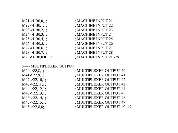
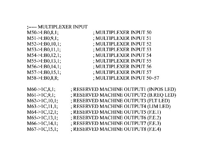
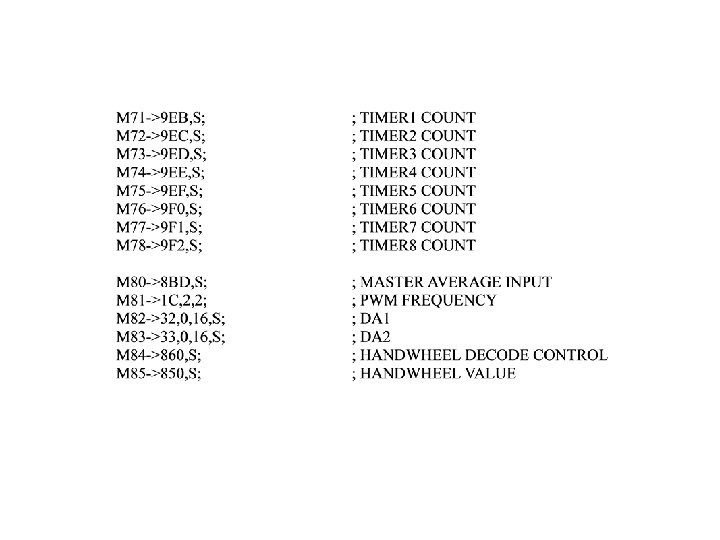
Suggested M-Variable Definition ; All These variables are defined in 400 V 210. UTC, download , this file to use ; M 0 ->9 E 9, 0, 24, S; ; INTERRUPT COUNTER ; GENERAL PURPOSE INPUTS AND OUTPUTS M 1 ->22, 0, 1; ; MACHINE OUTPUT 1 M 2 ->22, 1, 1; ; MACHINE OUTPUT 2 M 3 ->22, 2, 1; ; MACHINE OUTPUT 3 M 4 ->22, 3, 1; ; MACHINE OUTPUT 4 M 5 ->22, 4, 1; ; MACHINE OUTPUT 5 M 6 ->22, 5, 1; ; MACHINE OUTPUT 6 M 7 ->22, 6, 1; ; MACHINE OUTPUT 7 M 8 ->22, 7, 1; ; MACHINE OUTPUT 8 M 9 ->22, 0, 8; ; MACHINE OUTPUT 1 -8 BYTE M 11 ->I: 2 F, 0, 1; M 12 ->I: 2 F, 1, 1; M 13 ->I: 2 F, 2, 1; M 14 ->I: 2 F, 3, 1; M 15 ->I: 2 F, 4, 1; M 16 ->I: 2 F, 5, 1; M 17 ->I: 2 F, 6, 1; M 18 ->I: 2 F, 7, 1; M 19 ->I: 2 F, 0, 8; ; MACHINE INPUT 11 ; MACHINE INPUT 12 ; MACHINE INPUT 13 ; MACHINE INPUT 14 ; MACHINE INPUT 15 ; MACHINE INPUT 16 ; MACHINE INPUT 17 ; MACHINE INPUT 18 ; MACHINE INPUT 11~18

; REGISTERS ASSOCIATED WITH AXISx Mx 01 Mx 02 Mx 03 Mx 04 Mx 05 Mx 14 Mx 16 Mx 17 Mx 20 Mx 21 Mx 22 Mx 23 Mx 24 Mx 31 Mx 32 Mx 33 Mx 39 Mx 40 Mx 41 ; #x 16 -BIT UPDOWN COUNTER (COUNTS) ; #x SPEED CODE (UNIT: 16 COUNT/MSEC) ; #x 16 -BIT CAPTURE REGISTER (COUNTS) ; #x CAPTURED INDEX ; ADCx 12 -BIT ANALOG INPUT (BUFFERED) ; #x SERVO ON/OFF ; #x ENCODER CAPTURED FLAG ; #x POSITION CAPTURED FLAG (MUST CLEARED AFTER READ) ; HMFLx INPUT STATUS ; -LIMx INPUT STATUS ; +LIMx INPUT STATUS ; FAULTx INPUT STATUS ; HMFLx INPUT STATUS ; #x POSITIVE LIMIT SET ; #x NEGATIVE LIMIT SET ; #x ABORT FLAG ; #x DRIVER ENABLE BIT ; #x IN-POSITION BIT ; #x JOG IN PROGRESS

Mx 42 Mx 43 Mx 44 Mx 45 Mx 47 Mx 48 Mx 61 Mx 62 Mx 63 Mx 64 Mx 65 Mx 66 Mx 67 Mx 68 Mx 69 Mx 91 Mx 92 Mx 93 ; #x HOME IN PROGRESS ; #x DRIVER FAULT SET ; #x FATAL FOLLOWING ERROR ; #x HOME COMPLETE ; #x INC MODE ; #x JOG SEGMENT (4 MEANS ACC/DECEL COMPLETE) ; #x COMMAND POSITION (COUNTS) ; #x ACTUAL POSITION (COUNTS) ; #x JOG REGISTER POSITION (COUNTS) ; #x POSITION BIAS (COUNTS) ; #x COORDINATE TARGET POSITION (USER UNITS) ; #x COORDINATE TARGET POSITION (COUNTS) ; #x ACTUAL VELOCITY (UNIT: COUNTS/MSEC) ; #x PRESENT MASTER VELOCITY (UNIT: COUNTS/MSEC) ; #x COMMAND VELOCITY (UNIT: COUNTS/MSEC) ; #x AXIS SCALE ; #x AXIS DEFINITION ; #x DEFINED IN WHICH C. S.

; Registers associated with coordinate system x Mx 80 Mx 81 Mx 82 Mx 83 Mx 84 Mx 85 Mx 86 Mx 87 Mx 88 Mx 89 Mx 90 Mx 95 Mx 97 Mx 98 ; M 599. . 631 M 649. . 671 M 699. . 731 M 749. . 771 ; &x RUN REQUEST ; BUFFER OPENED ; INS MODE ; &x PROGRAM HOLD ; &x PROGRAM NUMBER ; &x RAPID MODE ; &x LINEAR MODE ; &x CIR MODE (-1: CIR 1 / 1: CIR 2) ; &x CALL STACK POINTER ; &x DWELL IN PROGRESS ; <RESERVED> ; &x HOME IN PROGRESS ; &x COMMAND FEEDRATE OVERRIDE ; &x PRESENT FEEDRATE OVERRIDE ; Registers associated with #1 captured data ; Registers associated with #2 captured data ; Registers associated with #3 captured data ; Registers associated with #4 captured data

; DEFINITION OF FIRST MT 0170 ; M 900. . 931 ; IN 1. . 32 M 932. . 947 ; OUT 1. . 16 ; ; DEFINITION OF SECONT MT 0170 ; M 950. . 981 ; IN 1. . 32 M 982. . 997 ; OUT 1. . 16 ; 0 C 00 0 FFF M-Var Definition Buffer (1024 words) L: 1000 13 FF P-Variables Buffer (1024 words) L: 1400 17 FF Q-Variables Buffer (1024 words) 1800 C 3 DF Motion and PLC Programs Buffer (44000 words) C 3 E 0 C 45 F Internal Used Buffer(128 words) C 460 C 67 F Interpreter Temporary Used Buffer(544 words) C 680 C 6 BF Open Buffer, Cleared to 0 on Power Up(64 words) C 6 C 0 C 6 FF Open Buffer (64 words) C 700 C 77 F PLC Online Command Buffer (128 words) C 780 C 7 FF Online Command Buffer (128 words) C 800 CBFF M-Variables Buffer (1024 words)
- Slides: 93