DNT 253 PROGRAMMABLE LOGIC CONTROLLER Converting Relay Schematics

DNT 253 PROGRAMMABLE LOGIC CONTROLLER Converting Relay Schematics into PLC Ladder Programs
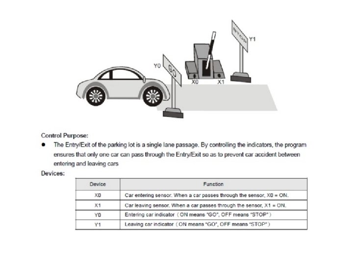
. • Stop button")
Sequential process control • Start button to run the motor (conveyor). • Stop button as emergency stop button. • Conveyor will automatically stop when box reach limit switch. • Green pilot light indicate conveyor moving • Red pilot light indicate conveyor stop moving

Sequential process control relay schematic. 1. Start button is pressed. 2. Table motor is started. 3. Package moves to the position of the limit switch and automatically stops. 4. A stop button will stop the table for any reason, before the package reaches the limit switch position 5. A red pilot light to indicate the table is stop 6. A green pilot light to indicate the table is running

Normally closed contact in series connection

Normally closed contact in parallel connection

• Problem Description • Consider the design of a Burglar Alarm for a house. This alarm will be activated if an unauthorized person is detected by a Window Sensor or a Motion Detector. Implement this Alarm System in PLC using Ladder Diagram programming language.

Problem Description A feeder drops material on the conveyor which sends material for further process through one more conveyor. Conveyor must start automatically when material is dropped on it. Implement automation of this in PLC using Ladder Diagram programming language.

Problem Solution Feeder has a motor mounted to feed material on conveyor belts. Load cells are installed at the bottom of conveyor belts to detect if material is present on the conveyor belt. When material falls on conveyor belt 1, motor 1 should start, and when material in present on conveyor belt 2, motor 2 remain On. Switches can also be used sometimes to detect material’s presence. But for more reliable operation, Load cells can be used as shown in the diagram above.

Problem Description One open tank is installed in the plant of which liquid level is to be controlled. When level reaches the Level Low, Outlet flow is blocked and inlet flow is allowed until high level is achieved. And when Level High is detected, outlet flow is allowed and inlet flow is blocked

Problem Solution To detect high and low level of liquid in the tank, two level switches are used which gives output in digital terms, that is when corresponding levels are detected, it gives output high otherwise remain low. To control level of this system, Single Acting piston valve can be used which has two states, either fully open or fully close. Low Level Switch is mounted at the bottom of the tank and Level High switch mounted at the side upper most position. When this inputs are detected, output to Control Valve has to be latched in order to continuously fill or empty the system. Master start/stop is also provided to shut down or start the entire process.

Process used to control the level of water in a storage tank. To control the level of water in a storage tank by turning the discharge pump on or off. The modes of operation are to be programmed as follows: OFF position – The water pump will stop if it is running and will not start if it is stop. Manual mode – The pump will start if the water in the tank is at any level except low. Automatic Mode - When the level of water reaches the high point, the pump will start. So the water can be removed from the tank, thus lowering the level. -When the water level reaches the low point, the pump will stop. -Status indicating light- water pump running light (green) -Low water level status light (red) -High water level status light (yellow)

Sequential process control relay schematic. A pump is to be used to fill two storage tanks, the pump is manually started by the operator from start/stop section. when the first tank is full, the control logic must be able to automatically stop flow to the first tank and direct flow to the second tank through the use of sensors and electric solenoid valves. when the second tank is full the pump must be shut down automatically. indicator lamps are to be included to signal when each tank is full. write the ladder program

A motorized overhead garage door is to be operated automatically to preset open and closed positions.

PLC Program to Operate Drilling of Parts Problem Description Whenever a part is placed on the drilling table, pneumatic clamper clamps the part and drilling process is done. When drilling is done, clamper releases the part by releasing pressure. When another part is detected, the process is repeated. Implement this in PLC using Ladder Diagram programming language.
- Slides: 17