Lecture 23 Filters Hungyi Lee Filter Types Lowpass


 If vl is output Lowpass filter If")
")


")


 Peaking")


")

 Infinity (X) Low-pass Filter DC (X) Infinity")


. One Filter")
 Overall Transfer Function: 2")
 2 st Filter with")
 2 st Filter with")

 or If")


=8. 57 cos(0. 6ω1 t-31。)")


- Slides: 106
Lecture 23 Filters Hung-yi Lee
Filter Types Lowpass filter Bandpass filter wco : cutoff frequency Bandwidth B = wu - wl Highpass filter Notch filter
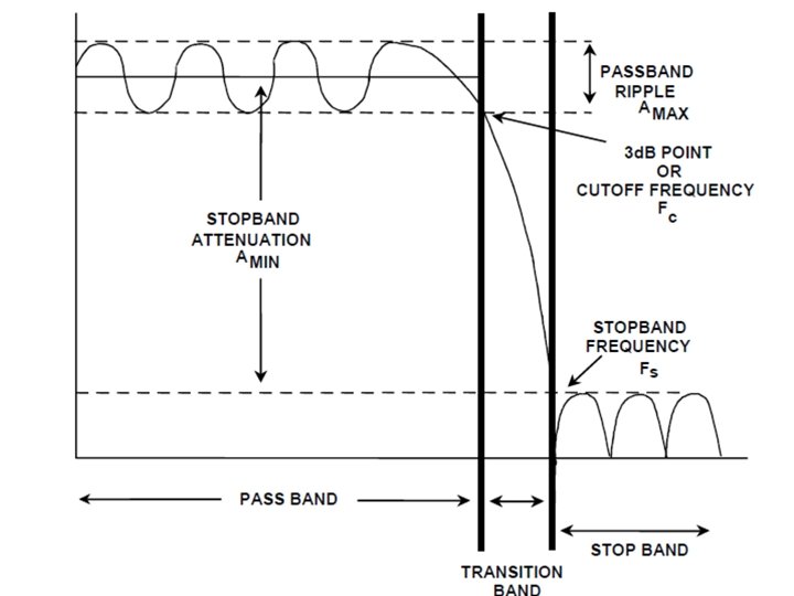
Real World Ideal filter
Transfer Function – Rules • Filter is characterized by its transfer function The poles should be at the left half of the s-plane. We only consider stable filter. Given a complex pole or zero, its complex conjugate is also pole or zero.
Transfer Function – Rules • Filter is characterized by its transfer function : improper filter As the frequency increase, the output will become infinity. : proper filter We only consider proper filer. The filters consider have more poles than zeros.
Filter Order = n The order of the denominator is the order of the filter. order=1 order=4
Outline • Textbook: Chapter 11. 2 Second-order Filter First-order Filters Lowpass Filter Highpass Filter Bandpss Filter Notch Filter
First-order Filters
Firsr-order Filters zero or first order Case 1: 1 pole, 0 zero Case 2: 0 or 1 zero 1 pole, 1 zero
Firsr-order Filters - Case 1 Lowpass filter As ω increases Magnitude decrease Phase decrease Pole p is on the negative real axis
Firsr-order Filters - Case 1 • Amplitude of the transfer function of the first-order low pass filter Ideal Lowpass filter First-order Lowpass filter
Firsr-order Filters - Case 1 • Find cut-off frequency ωco of the first-order low pass filter At DC Lowpass filter Find cut-off frequency ωco such that
Firsr-order Filters - Case 2 -1: Absolute value of zero is smaller than pole Zero can be positive or negative Ø Magnitude is proportional to the length of green line divided by the length of the blue line Ø Low frequency ≈ |z|/|p| Because |z|<|p| The low frequency signal will be attenuated If z=0, the low frequency can be completely block Not a low pass
Firsr-order Filters - Case 2 -1: Absolute value of zero is smaller than pole Ø Magnitude is proportional to the length of green line divided by the length of the blue line Ø High frequency The high frequency signal will pass If z=0 (completely block low frequency) High pass
First-order Filters - Case 2 • Find cut-off frequency ωco of the first-order high pass filter (the same as low pass filter)
First-order Filters - Case 2 -2: Absolute value of zero is larger than pole Ø Low frequency ≈ |z|/|p| Because |z|>|p| The low frequency signal will be enhanced. Ø High frequency: magnitude is 1 The high frequency signal will pass. Neither high pass nor low pass
First-order Filters Consider vin as input (pole) If vl is output Lowpass filter If vh is output Highpass filter (pole)
First-order Filters (pole)
Cascading Two Lowpass Filters
Cascading Two Lowpass Filters
Cascading Two Lowpass Filters The first low pass filter is influenced by the second low pass filter!
Cascading Two Lowpass Filters
Cascading Two Lowpass Filters
Second-order Filters
Second-order Filter 0, 1 or 2 zeros Second order Must having two poles 2 poles Case 1: No zeros Case 2: One zeros Case 3: Two zeros
Second-order Filter – Case 1 -1 Case 1 -2
Second-order Filter – Case 1 -1 Real Poles The magnitude is As ω increases The magnitude monotonically decreases. Decrease faster than first order low pass
Second-order Filter – Case 1 -2 Complex Poles The magnitude is As ω increases, l 1 decrease first and then increase. l 2 always increase What will happen to magnitude? 1. Increase 2. Decrease 3. Increase, then decrease 4. Decrease, then increase
Second-order Filter – Case 1 -2 Complex Poles If ω > ωd l 1 and l 2 both increase. The magnitude must decrease. What will happen to magnitude? 1. Increase 2. Decrease 3. Increase, then decrease 4. Decrease, then increase
Second-order Filter – Case 1 -2 Complex Poles When ω < ωd Maximize the magnitude Minimize
Second-order Filter – Case 1 Minimize (maximize)
Second-order Filter – Case 1 Lead to maximum The maxima exists when No Peaking
Second-order Filter – Case 1 Lead to maximum The maxima exists when Assume Peaking
Second-order Filter – Case 1 For complex poles
Second-order Filter – Case 1 Q times of DC gain
Second-order Filter – Case 1 Lead to maximum For complex poles
Second-order Filter – Case 1 Lead to maximum The maximum value is The maximum exist when
Second-order Filter – Case 1 -1 Real Poles Case 1 -2 Complex Poles (No Peaking) Which one is considered as closer to ideal low pass filter?
Complex poles (Butterworth filter) Peaking
Butterworth – Cut-off Frequency ω0 is the cut-off frequency for the second-order lowpass butterworth filter (Go to the next lecture first)
Second-order Filter – Case 2: 2 poles and 1 zero Case 2 -1: 2 real poles and 1 zero
Second-order Filter – Case 2: 2 poles and 1 zero Case 2 -1: 2 real poles and 1 zero flat Bandpass Filter
Second-order Filter – Case 2 -2: 2 complex poles and 1 zero Two Complex Poles -40 d. B + Zero +20 d. B
Second-order Filter – Case 2 -2: 2 complex poles and 1 zero -40 d. B -20 d. B Two Complex Poles -40 d. B + +20 d. B -20 d. B Zero +20 d. B
Second-order Filter – Case 2 -2: 2 complex poles and 1 zero Highly Selective +20 d. B -20 d. B Two Complex Poles -40 d. B + Zero Bandpass Filter +20 d. B
Bandpass Filter • Bandpass filter: 2 poles and zero at original point Find the frequency for the maximum amplitude bandpass filter ω0
Bandpass Filter • Find the frequency for the maximum amplitude
Bandpass Filter • Find the frequency for the maximum amplitude is maximized when (Center frequency) The maximum value is K’. (Bandpass filter)
Bandpass Filter is maximized when The maximum value is K’. bandpass filter B Bandwidth B = ωr - ωl
Bandpass Filter - Bandwidth B Four answers? Pick the two positive ones as ωl or ωr
Bandpass Filter - Bandwidth B Q measure the narrowness of the pass band Q is called quality factor
Bandpass Filter Ø Usually require a specific bandwidth Ø The value of Q determines the bandwidth. Ø When Q is small, the transition would not be sharp.
Stagger-tuned Bandpass Filter
Stagger-tuned Bandpass Filter - Exercise 11. 64 Bandpass Filter Center frequency: 10 Hz Bandpass Filter Center frequency: 40 Hz We want flat passband. Tune the value of Q to achieve that
Stagger-tuned Bandpass Filter - Exercise 11. 64 Test Different Q Q=3 Q=1 Q=0. 5
Second-order Filter – Case 3 • Case 3: Two poles, Two zeros Case 3 -1: Two real zeros Two real poles Two Complex poles High-pass
Second-order Filter – Case 3: Two poles, Two zeros Case 3 -2: Two Complex zeros Fix ω0 Larger Q Larger θ Fix ωβ Larger Q β Larger θ β
Second-order Filter – Case 3: Two poles, Two zeros Case 3 -2: Two Complex zeros Two poles Two zeros -40 d. B +40 d. B
Second-order Filter – Case 3: Two poles, Two zeros Case 3 -2: Two Complex zeros High-pass Notch
Second-order Filter – Case 3: Two poles, Two zeros Case 3 -2: Two Complex zeros Two poles Two zeros -40 d. B +40 d. B
Second-order Filter – Case 3: Two poles, Two zeros Case 3 -2: Two Complex zeros Low-pass Notch
Second-order Filter – Case 3: Two poles, Two zeros Case 3 -2: Two Complex zeros Two poles Two zeros Large Q -40 d. B +40 d. B small Qβ
Second-order Filter – Case 3: Two poles, Two zeros Case 3 -2: Two Complex zeros
Second-order Filter – Case 3: Two poles, Two zeros Case 3 -2: Two Complex zeros Two poles small Q Two zeros +40 d. B -40 d. B Larger Qβ
Second-order Filter – Case 3: Two poles, Two zeros Case 3 -2: Two Complex zeros Standard Notch Filter
Second-order Filter – Case 3: Two poles, Two zeros Case 3 -2: Two Complex zeros If the two zeros are on the ω axis The notch filter will completely block the frequency ω0
Notch Filter The extreme value is at ω= ω0 (Notch filter)
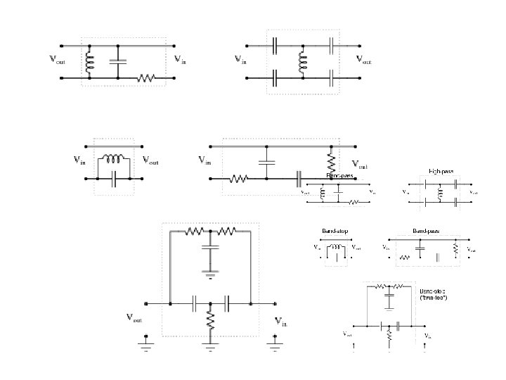
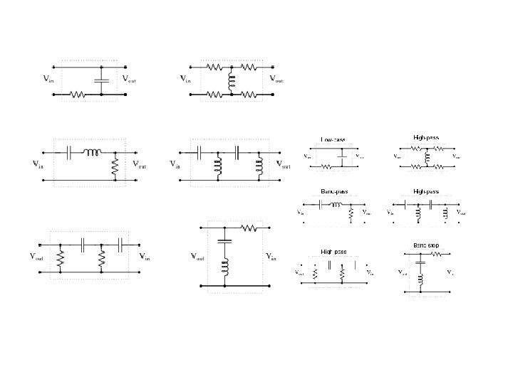
Second-order RLC Filters A B C D RLC series circuit can implement high-pass, lowpass, band-pass and notch filter.
Second-order RLC Filters B A DC (O) Infinity (X) Low-pass Filter DC (X) Infinity (O) High-pass Filter
Second-order RLC Filters C Band-pass Filter
Second-order RLC Filters – Band-pass C 40 p. F to 360 p. F L=240μH, R=12Ω Frequency range Center frequency: Max: 1. 6 MHz min: 0. 54 MHz
Second-order RLC Filters – Band-pass C 40 p. F to 360 p. F L=240μH, R=12Ω Frequency range 0. 54 MHz ~ 1. 6 MHz Q is 68 to 204.
Band-pass
Band-pass Filter
Second-order RLC Filters C D Notch Filter
Active Filter
Basic Active Filter -i i 0 0
First-order Low-pass Filter
First-order High-pass Filter
Active Band-pass Filter
Active Band-pass Filter ?
Loading The loading Z will change the transfer function of passive filters. The loading Z will NOT change the transfer function of the active filter.
Cascading Filters If there is no loading The transfer function is H(s). One Filter Stage Model
Cascading Filters 1 st Filter with transfer function H 1(s) Overall Transfer Function: 2 st Filter with transfer function H 2(s)
Cascading Filters 1 st Filter with transfer function H 1(s) 2 st Filter with transfer function H 1(s)
Cascading Filters 1 st Filter with transfer function H 1(s) 2 st Filter with transfer function H 1(s) If zero output impedance (Zo 1=0) or If infinite input impedance (Zi 2=∞)
Cascading Filters – Input & Output Impedance
Cascading Filters – Basic Active Filter If zero output impedance (Zo 1=0) or If infinite input impedance (Zi 2=∞) -i =0 0 0 =0 0
Active Notch Filter A B Which one is correct?
Active Notch Filter Low-pass Filter High-pass Filter Add Together
Homework • 11. 19
Thank you!
Answer • 11. 19: Ra=7. 96 kΩ, Rb= 796Ω, va(t)=8. 57 cos(0. 6ω1 t-31。) +0. 83 cos(1. 2ω2 t-85。) vb(t)=0. 60 cos(0. 6ω1 t+87。) +7. 86 cos(1. 2ω2 t+40。) (ω1 and ω2 are 2πf 1 and 2πf 2 respectively) • 11. 22: x=0. 14, ωco=0. 374/RC • 11. 26(refer to P 494): ω0=2π X 6 X 10^4, B= ω0=2π X 5 X 10^4, Q=1. 2, R=45. 2Ω, C=70. 4 n. F • 11. 28(refer to P 494): C=0. 25μF, Qpar=100, Rpar=4 kΩ, R||Rpar=2 kΩ, R=4 kΩ
Appendix
Aliasing Sampling Wrong Interpolation Actual signal High frequency becomes low frequency
Phase filter
Table 11. 3 Simple Filter Type Transfer Function Properties Lowpass Highpass Bandpass Notch 98
Loudspeaker for home usage with three types of dynamic drivers 1. Mid-range driver 2. Tweeter 3. Woofers
https: //www. youtube. com/watch? v=3 I 62 Xfhts 9 k
From Wiki • Butterworth filter – maximally flat in passband stopband for the given order • Chebyshev filter (Type I) – maximally flat in stopband, sharper cutoff than Butterworth of same order • Chebyshev filter (Type II) – maximally flat in passband, sharper cutoff than Butterworth of same order • Bessel filter – best pulse response for a given order because it has no group delay ripple • Elliptic filter – sharpest cutoff (narrowest transition between pass band stop band) for the given order • Gaussian filter – minimum group delay; gives no overshoot to a step function.
Link • http: //www. ti. com/lsds/ti/analog/webench/weben ch-filters. page • http: //www. analog. com/designtools/en/filterwizar d/#/type
Suppose this band-stop filter were to suddenly start acting as a high-pass filter. Identify a single component failure that could cause this problem to occur: If resistor R 3 failed open, it would cause this problem. However, this is not the only failure that could cause the same type of problem!