How to treat ailing and failing implants Roland








- Slides: 176
How to treat ailing and failing implants Roland M. Meffert Implant dentistry, spring, 1992
1. Ailing implant 2. Failing implant 3. Failed implant
Definition of ailing implant 1. Exhibits bone loss with pocketing; the situation seems to be static at the 3 - to 4 -month maintenance checks. 2. A lamina dura indicating a state of chronicity may be present at the borders of the osseous defect. Meffert, 1992, Implant dentistry
Definition of failing implant 1. May evidence bone loss, pocketing, bleeding upon probing, purulence 2. Bone loss patterns are progressing irrespective of therapy. Meffert, 1992, Implant dentistry
Definition of failed implant 1. Has mobility, a dull sound when percussed, and radiographically a peri-implant radiolucency 2. The failed implant must be removed since it is nonfunctional and bone loss will continue. Meffert, 1992, Implant dentistry
Chemical treatment and the removal of LPS 1. Antibiotic tetracycline did not have much effect in removing the LPS endotoxin from the hydroxyapatite (HA) when used in concentration of 50 mg/ml (p. H 2 to 3) and it significantly altered the inner and outermost calcium to phosphorus ratios of the HA coating. 2. Hydrogen peroxide did not remove LPS to any degree. Zablotsky et al. , 1991, Unpublished data
Chemical treatment and the removal of LPS 3. Chlorhexidine gluconate and stannous fluoride seemed to bind rather than remove the LPS to the coated surface. 4. Both chlorhexidine and HA are highly charged and there may be an interaction which would bind the LPS to the HA surface; the same may be true of stannous fluoride. Zablotsky et al. , 1991, Unpublished data
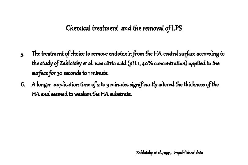
Chemical treatment and the removal of LPS 5. The treatment of choice to remove endotoxin from the HA-coated surface according to the study of Zablotsky et al. was citric acid (p. H 1, 40% concentration) applied to the surface for 30 seconds to 1 minute. 6. A longer application time of 2 to 3 minutes significantly altered the thickness of the HA and seemed to weaken the HA substrate. Zablotsky et al. , 1991, Unpublished data
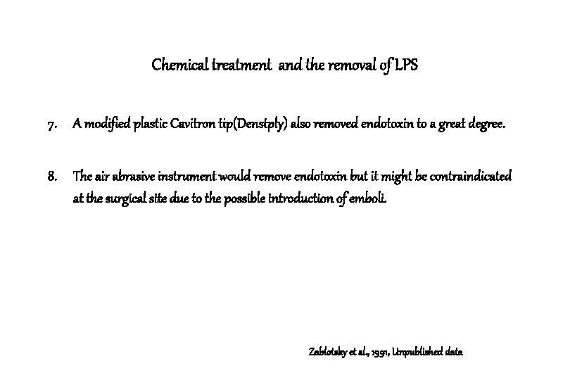
Chemical treatment and the removal of LPS 7. A modified plastic Cavitron tip(Denstply) also removed endotoxin to a great degree. 8. The air abrasive instrument would remove endotoxin but it might be contraindicated at the surgical site due to the possible introduction of emboli. Zablotsky et al. , 1991, Unpublished data
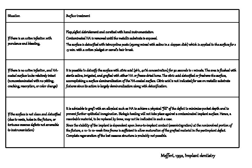
Situation Surface treatment If there is an active infection with purulence and bleeding, Flap, defect debridement and curetted with hand instrumentation Contaminated HA is removed until the metallic substrate is exposed. The surface is detoxified with tetracycline paste (250 mg mixed with saline in a dappen dish) which is applied to the surface for 2 -3 min. with a cotton pledget or camel’s hair brush If there is no active infection, and HAcoated surface looks relatively intact (noncontaminated with no pitting, cracking, resorption, or color change) It is possible to detoxify the surface with citric acid (p. H 1, 40% concentration) for 30 seconds to 1 minute. The area is flushed with sterile saline, irrigated, and grafted with either HA or freeze-dried bone. The citric acid detoxified or freshens the surface, accomplishing a surface demineralization of the HA-coated surface. Citric acid is not indicated for use on metallic substrate fixtures since its action is largely demineralization along with detoxification. If the surface is not clean and detoxified (due to vents, holes in the fixture, or tortuous osseous defects not amenable to instrumentation) It is advisable to graft with an alloplast such as HA to achieve a physical “fill” of the defect to minimize pocket depth and to prevent further epithelial invagination. Biologic healing will not take place against a contaminated implant surface. Hence, a resorbable material, to be replaced by bone, may not be indicated in such a case. Since the stability of the implant is dependent upon bone-to-implant contact (osseointegration) at the noninvolved portion of the fixture, a 10 - to 12 - week time frame is sufficient to allow maturation of the grafted material in the periimplant defect. Complete regeneration of the lost osseous structure is probably not possible. Meffert, 1992, Implant dentistry
Detoxification of endotoxin-contaminated titanium and hydroxyapatite-coated surfaces utilizing various chemotherapeutic and mechanical modalities Mark H. Zablotsky Dana. L. Diedrich Roland M. Meffert Implant dentistry, spring, 1992; 1 : 154 -158
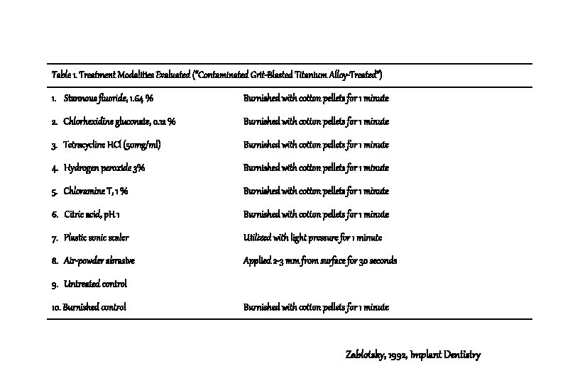
Table 1. Treatment Modalities Evaluated (“Contaminated Grit-Blasted Titanium Alloy-Treated”) 1. Stannous fluoride, 1. 64 % Burnished with cotton pellets for 1 minute 2. Chlorhexidine gluconate, 0. 12 % Burnished with cotton pellets for 1 minute 3. Tetracycline HCl (50 mg/ml) Burnished with cotton pellets for 1 minute 4. Hydrogen peroxide 3% Burnished with cotton pellets for 1 minute 5. Chloramine T, 1 % Burnished with cotton pellets for 1 minute 6. Citric acid, p. H 1 Burnished with cotton pellets for 1 minute 7. Plastic sonic scaler Utilized with light pressure for 1 minute 8. Air-powder abrasive Applied 2 -3 mm from surface for 30 seconds 9. Untreated control 10. Burnished control Burnished with cotton pellets for 1 minute Zablotsky, 1992, Implant Dentistry
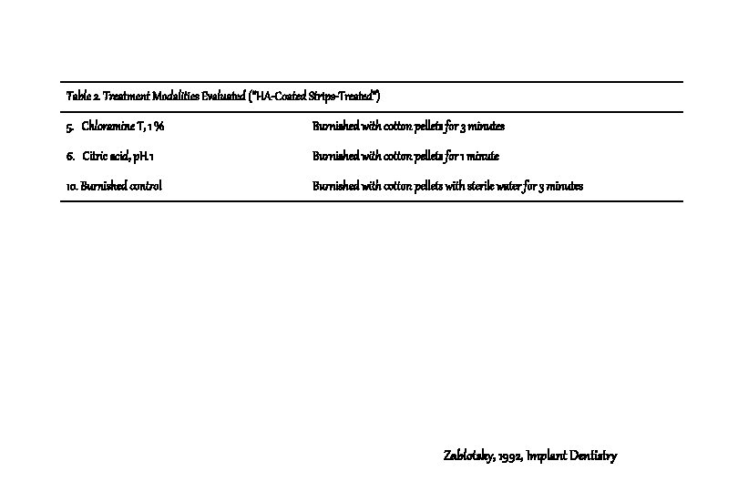
Table 2. Treatment Modalities Evaluated (“HA-Coated Strips-Treated”) 5. Chloramine T, 1 % Burnished with cotton pellets for 3 minutes 6. Citric acid, p. H 1 Burnished with cotton pellets for 1 minute 10. Burnished control Burnished with cotton pellets with sterile water for 3 minutes Zablotsky, 1992, Implant Dentistry
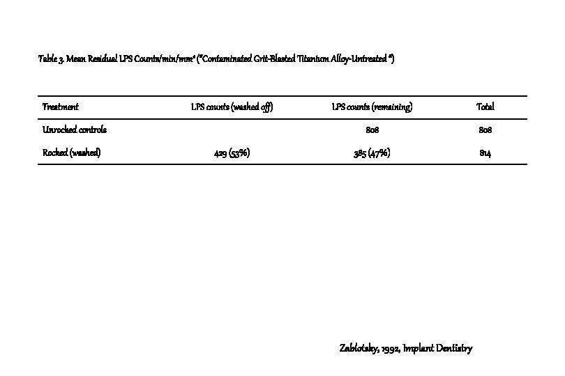
Table 3. Mean Residual LPS Counts/min/mm 2 (“Contaminated Grit-Blasted Titanium Alloy-Untreated “) Treatment LPS counts (washed off) Unrocked controls Rocked (washed) 429 (53%) LPS counts (remaining) Total 808 385 (47%) 814 Zablotsky, 1992, Implant Dentistry
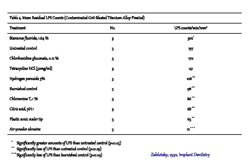
Table 4. Mean Residual LPS Counts (Contaminated Grit-Blasted Titanium Alloy-Treated) No. LPS counts/min/mm 2 Stannous fluoride, 1. 64 % 3 302* Untreated control 3 197 Chlorhexidine gluconate, 0. 12 % 3 170 Tetracycline HCl (50 mg/ml) 3 141 Hydrogen peroxide 3% 3 108 * * Burnished control 3 98 * * Chloramine T, 1 % 3 86 * * Citric acid, p. H 1 3 68 * * Plastic sonic scaler tip 3 63 * * Air-powder abrasive 3 12 * * * Treatment * Significantly greater amounts of LPS than untreated control (p<0. 05) * * Significantly less of LPS than untreated control (p<0. 05) * * * Significantly less of LPS than burnished control (p<0. 05) Zablotsky, 1992, Implant Dentistry
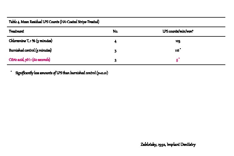
Table 4. Mean Residual LPS Counts (HA-Coated Strips-Treated) No. LPS counts/min/mm 2 Chloramine T, 1 % (3 minutes) 4 103 Burnished control (3 minutes) 3 116 * Citric acid, p. H 1 (60 seconds) 3 5* Treatment * Significantly less amounts of LPS than burnished control (p<0. 01) Zablotsky, 1992, Implant Dentistry
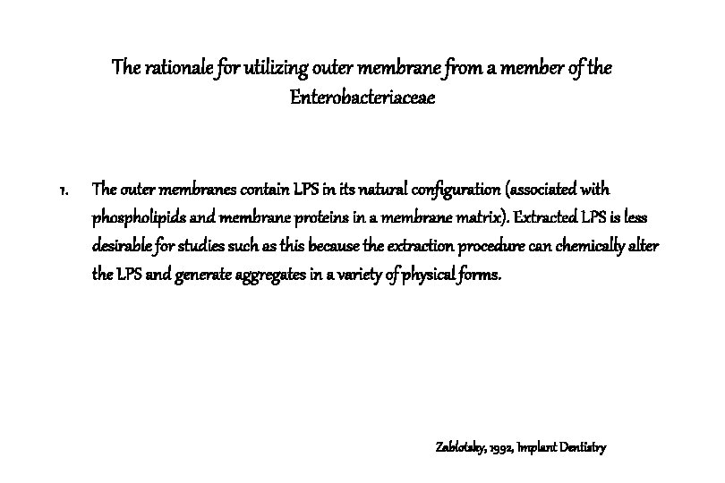
The rationale for utilizing outer membrane from a member of the Enterobacteriaceae 1. The outer membranes contain LPS in its natural configuration (associated with phospholipids and membrane proteins in a membrane matrix). Extracted LPS is less desirable for studies such as this because the extraction procedure can chemically alter the LPS and generate aggregates in a variety of physical forms. Zablotsky, 1992, Implant Dentistry
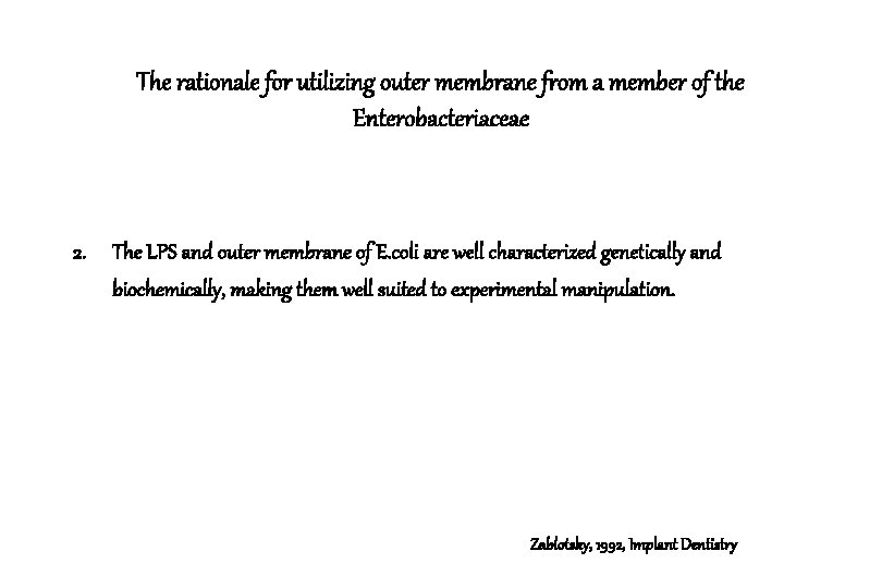
The rationale for utilizing outer membrane from a member of the Enterobacteriaceae 2. The LPS and outer membrane of E. coli are well characterized genetically and biochemically, making them well suited to experimental manipulation. Zablotsky, 1992, Implant Dentistry
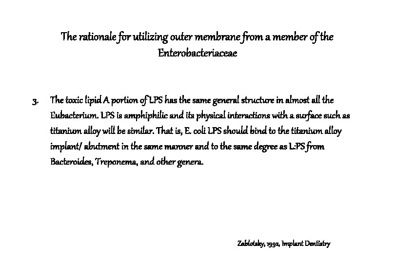
The rationale for utilizing outer membrane from a member of the Enterobacteriaceae 3. The toxic lipid A portion of LPS has the same general structure in almost all the Eubacterium. LPS is amphiphilic and its physical interactions with a surface such as titanium alloy will be similar. That is, E. coli LPS should bind to the titanium alloy implant/ abutment in the same manner and to the same degree as L: PS from Bacteroides, Treponema, and other genera. Zablotsky, 1992, Implant Dentistry
LPS binding to titanium and Its charateristics 1. It can be concluded that LPS would have a reduced affinity for polished abutments when compared with grit-blasted titanium surface. 2. It is interesting to note that burnishing the contaminated grit-blasted titanium surface with a cotton pellet dipped in sterile saline for 1 minute was effective in reducing LPS levels significantly below untreated controls. Zablotsky, 1992, Implant Dentistry
LPS-infected HA surface & Citric acid treatment 1. A short (30 -60 seconds) application of citric acid removed LPS without significantly altering the residual coating. 2. This treatment was also successful in returning the contaminated HA coating to a biologically acceptable surface on which human gingival fibroblasts could proliferate. Zablotsky et al, 1991, Unpublished data
LPS-infected HA surface & Citric acid treatment 3. Action mechanism of citric acid on the HA surface is thought to be a demineralized phenomenon of the most superficial layer of HA. 4. This obviously does not occur with the toxic titanium or titanium alloy surface. Athough a 1 minute application of citric acid was superior to saline burnishing for the same time interval, residual levels were not significantly less. Zablotsky et al, 1991, Unpublished data
LPS-infected HA surface & Stannous fluoride 1. The application of stannous fluoride to contaminated titanium alloy appears to bind greater levels of LPS to the surface when compared with untreated controls. 2. The mechanism for this is unknown, but may be due to changes in charge interactions among stannous fluoride, LPS, and HA and/or to the binding of the glycerol carrier in the stannous fluoride solution. Zablotsky et al, 1991, Unpublished data
Results 1. The air-powder abrasive unit removed significantly greater amounts of LPS than all other treatment modalities on titanium samples. (p<0. 05) 2. A 60 -second burnish with sterile water was able to remove significant amounts of LPS when compared with untreated controls. (p<0. 05) Zablotsky, 1992, Implant Dentistry
Results 3. Citric acid was superior in the removal of LPS from HA-coated surfaces when compared with the controls or chloramine T. (p<0. 01) Zablotsky, 1992, Implant Dentistry
Conclusion 1. Titanium alloy surfaces are at a lower risk to the binding of endotoxin than HA-coated surfaces. 2. If fixture modification is performed as part of a pocket elimination procedure, the use of chemotherapeutic agents or air-powder abrasives are probably not indicated. Zablotsky, 1992, Implant Dentistry
Conclusion 3. If regenerative techniques such as osseous grafting and guided tissue regeneration, are contemplated, chemotherapeutic agents or air-powder abrasive techniques appear to have merit in the treatment of the toxic surface. Zablotsky, 1992, Implant Dentistry
Guided bone regeneration in the treatment of periimplantitis Persson L. G. Ericsson I. Berglundh T. Lindhe J. Clinical Oral Implants Research, 1996: 7: 366 -372
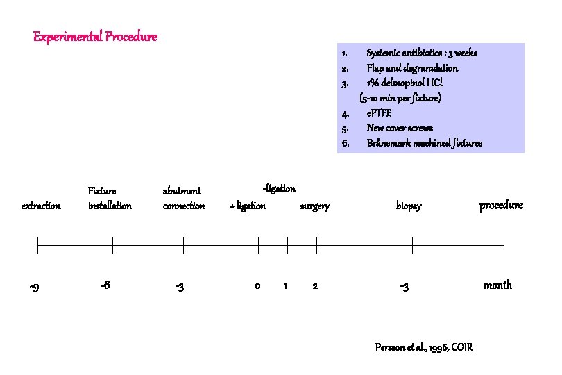
Experimental Procedure 1. 2. 3. Systemic antibiotics : 3 weeks Flap and degranulation 1% delmopinol HCl (5 -10 min per fixture) 4. e. PTFE 5. New cover screws 6. Brånemark machined fixtures extraction -9 Fixture installation -6 abutment connection -3 -ligation + ligation surgery 0 1 2 biopsy -3 Persson et al. , 1996, COIR procedure month
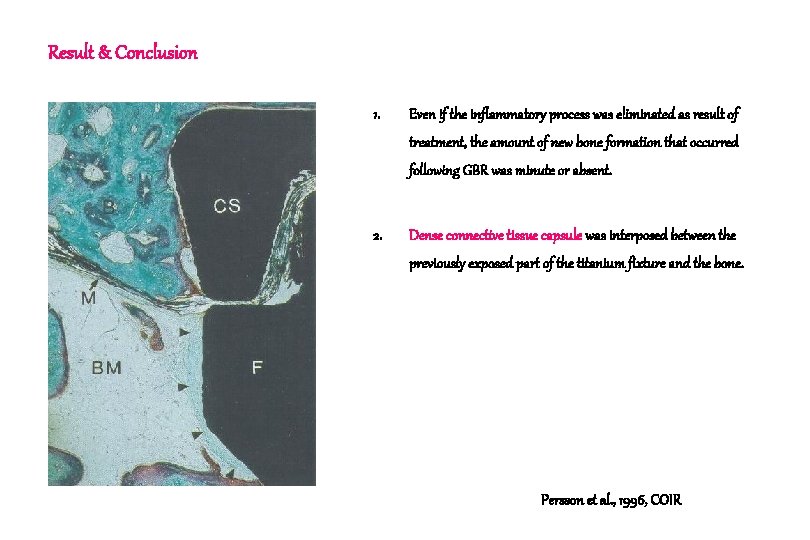
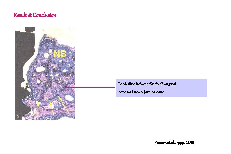
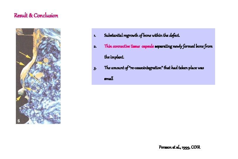
Result & Conclusion 1. Even if the inflammatory process was eliminated as result of treatment, the amount of new bone formation that occurred following GBR was minute or absent. 2. Dense connective tissue capsule was interposed between the previously exposed part of the titanium fixture and the bone. Persson et al. , 1996, COIR
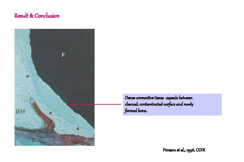
Result & Conclusion Dense connective tissue capsule between cleaned, contaminated surface and newly formed bone. Persson et al. , 1996, COIR
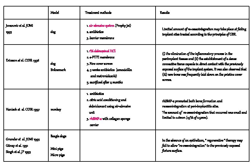
Model Jovanovic et al. JOMI 1993 Ericsson et al. COIR 1996 Hanisch et al. COIR 1997 Grunder et al. JOMI 1993 Günay et al. 1991 Singh et al. JP 1993 Treatment methods Results dog 1. air abrasive system (Prophy Jet) 2. antibiotics 3. barrier membrane Limited amount of re-osseointegration may take place at failing implant sites treated according to the principles of GBR. dog Brånemark 1. 1% delmopinol HCl 2. e-PTFE membrane 3. New cover screws 4. 3 weeks antibiotics (amoxicillin and metronidazole) 5. sacrificed after 4 months (i) the elimination of the inflammatory process in the periimplant tissues and (ii) the establishment of a dense connective tissue capsule in direct contact with the previously exposed surface of the implant system. It was also observed that (iii) new bone was frequently laid down on the pristine cover screws. monkey 1. antibiotics 2. citric acid conditioning and debridement using air-abrasive unit 3. rh. BMP-2 with collagen sponge carrier rh. BMP-2 promoted both bone formation and reosseointegration at peri-implantitis sites. The amount of re-osseointegration that occurred was small and limited to 0. 6 mm (25% of 2. 5 mm). Beagle dogs Mini pigs Micro pigs In the absence of an epithelium, “ regenerative “ therapy may fail to allow “re-osseointegration” to the previously exposed fixture surface.
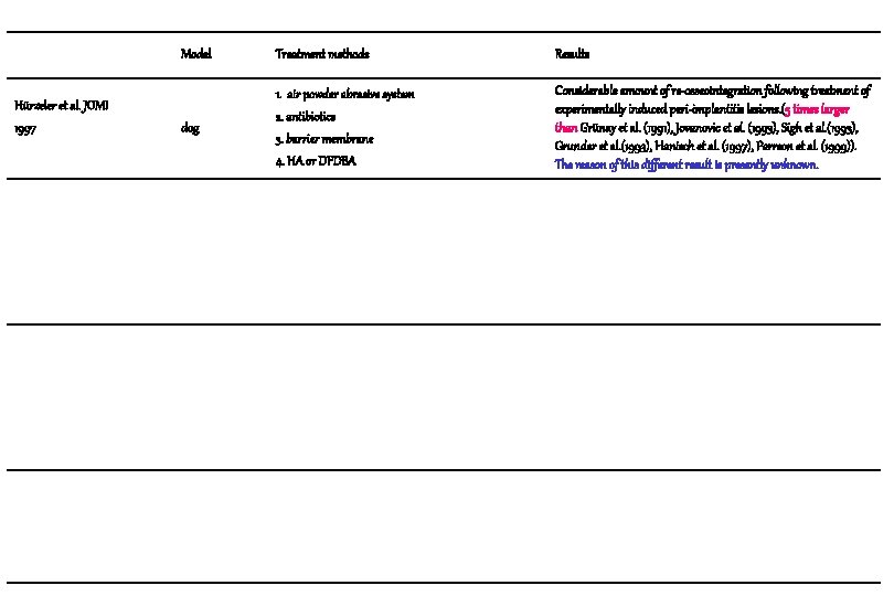
Hürzeler et al. JOMI 1997 Model Treatment methods Results dog 1. air powder abrasive system 2. antibiotics 3. barrier membrane 4. HA or DFDBA Considerable amount of re-osseointegration following treatment of experimentally induced peri-implantitis lesions. (5 times larger than Grünay et al. (1991), Jovanovic et al. (1993), Sigh et al. (1993), Grunder et al. (1993), Hanisch et al. (1997), Perrson et al. (1999)). The reason of this different result is presently unknown.
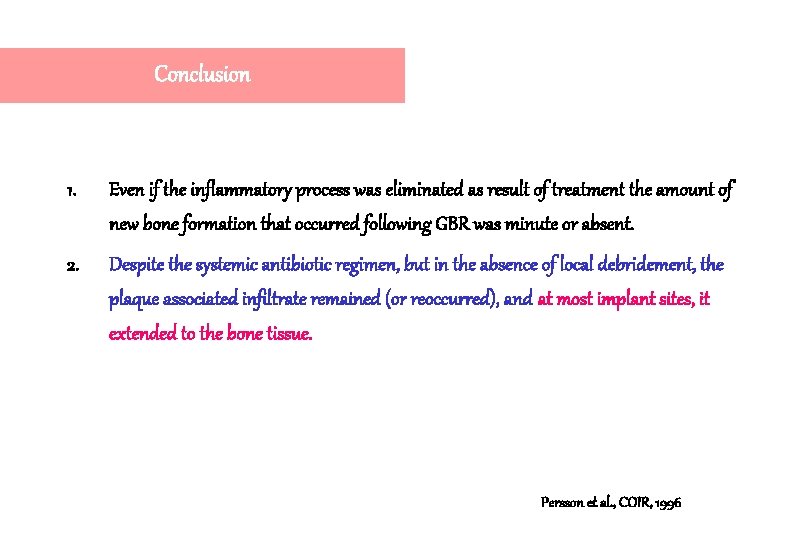
Conclusion 1. Even if the inflammatory process was eliminated as result of treatment the amount of new bone formation that occurred following GBR was minute or absent. 2. Despite the systemic antibiotic regimen, but in the absence of local debridement, the plaque associated infiltrate remained (or reoccurred), and at most implant sites, it extended to the bone tissue. Persson et al. , COIR, 1996
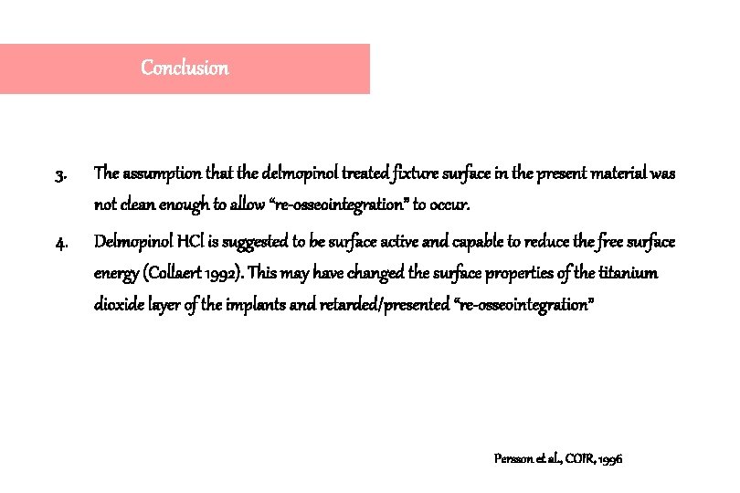
Conclusion 3. The assumption that the delmopinol treated fixture surface in the present material was not clean enough to allow “re-osseointegration” to occur. 4. Delmopinol HCl is suggested to be surface active and capable to reduce the free surface energy (Collaert 1992). This may have changed the surface properties of the titanium dioxide layer of the implants and retarded/presented “re-osseointegration” Persson et al. , COIR, 1996
Tissue response of Re-implanted cover screw 1. Retrieved cover screw from 5 patients. 2. Either rinsed in saline or exposed to ultrasonic cleaning and sterilization. 3. Subsequently implanted and retained for 6 weeks in the abdominal wall of the animals. Pristine sterile cover screws were used as controls. 4. Re-implanted cover screws, in comparison to the pristine cover screws, elicited a tissue response that included the formation of a thicker fibrous capsule and the presence of a larger number of macrophages in the vicinity of the implants. Sennerby et al. , JOMI, 1989
Resolution of peri-implantitis following treatment Persson L. G. Araújo M. G. Berglundh T. Gröndahl K. Lindhe J. Clinical Oral Implants Research, 1999: 10: 195 -203
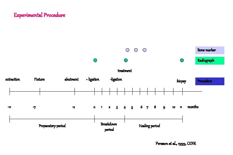
Experimental Procedure Bone marker Radiograph treatment extraction -11 Fixture abutment -7 -2 Preparatory period + ligation 0 -ligation 1 2 3 Breakdown period biopsy 4 5 6 7 8 9 10 11 Procedure months Healing period Persson et al. , 1999, COIR
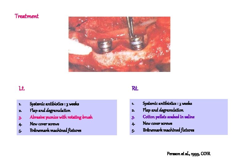
Treatment Lt. 1. 2. 3. 4. 5. Rt. Systemic antibiotics : 3 weeks Flap and degranulation Abrasive pumice with rotating brush New cover screws Brånemark machined fixtures 1. 2. 3. 4. 5. Systemic antibiotics : 3 weeks Flap and degranulation Cotton pellets soaked in saline New cover screws Brånemark machined fixtures Persson et al. , 1999, COIR
Result & Conclusion Borderline between the “old” original bone and newly formed bone Persson et al. , 1999, COIR
Result & Conclusion 1. Substantial regrowth of bone within the defect. 2. Thin connective tissue capsule separating newly formed bone from the implant. 3. The amount of “re-osseointegration” that had taken place was small Persson et al. , 1999, COIR
Surface energy, Contamination and Tissue Response 1. Native titanium oxide layer provides the implant with a high surface energy(reduced contact angle)which seems to facilitate implant to tissue interaction and integration. 2. If the implant during handling becomes contaminated, a low energy surface (increased contact angle) will form which, following implant installation, may elicit a foreign body reaction. 3. Such a contaminated implant will be surrounded by a dense, connective tissue capsule which separates the “foreign body” from the adjacent host tissue. Bair & Meyer JOMI 1988
Result 1. The lateral aspect of the coronal part of the fixture, I. e. the previously contaminated portion, was in all experimental sites covered by a dense connective tissue capsule that separated the newly formed bone from the implant. 2. This capsule which was between 50 and 200 m wide, was consistently devoid of inflammatory cells but contained large numbers of collagen fibers which runs a course parallel to the fixture surface. Persson et al. , COIR, 1999
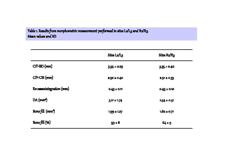
Table 1. Results from morphometric measurement performed in sites L 2/L 3 and R 2/R 3. Mean values and SD Sites L 2/L 3 Sites R 2/R 3 C/F-BD (mm) 3. 34 ± 0. 29 3. 35 ± 0. 40 C/F-CBI (mm) 2. 92 ± 0. 40 2. 91 ± 0. 33 Re-osseointegration (mm) 0. 43 ± 0. 11 0. 43 ± 0. 10 DA (mm 2) 3. 21 ± 1. 74 2. 54 ± 0. 91 Bone fill (mm 2) 1. 99 ± 1. 27 1. 62 ± 0. 71 59 ± 8 64 ± 9 Bone fill (%)
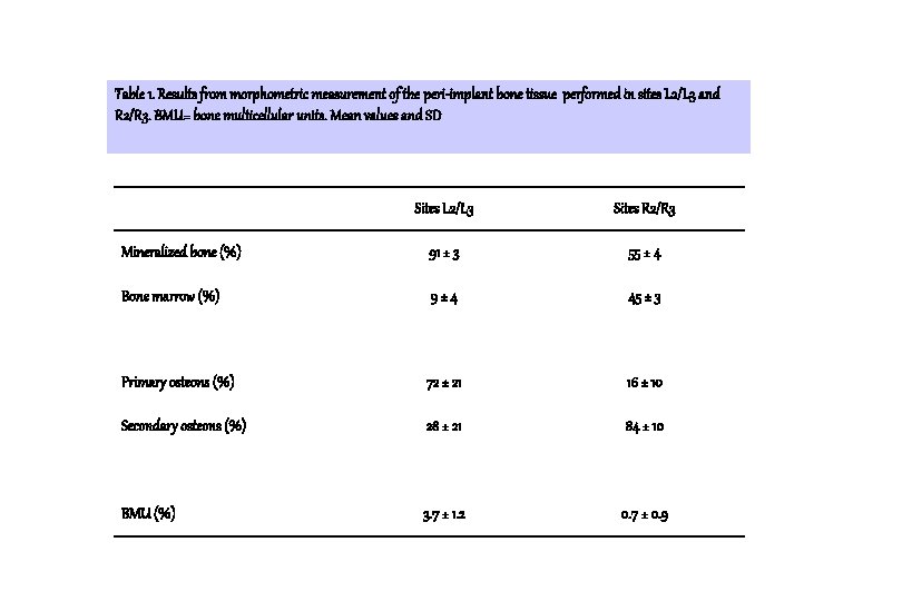
Table 1. Results from morphometric measurement of the peri-implant bone tissue performed in sites L 2/L 3 and R 2/R 3. BMU= bone multicellular units. Mean values and SD Sites L 2/L 3 Sites R 2/R 3 Mineralized bone (%) 91 ± 3 55 ± 4 Bone marrow (%) 9± 4 45 ± 3 Primary osteons (%) 72 ± 21 16 ± 10 Secondary osteons (%) 28 ± 21 84 ± 10 BMU (%) 3. 7 ± 1. 2 0. 7 ± 0. 9
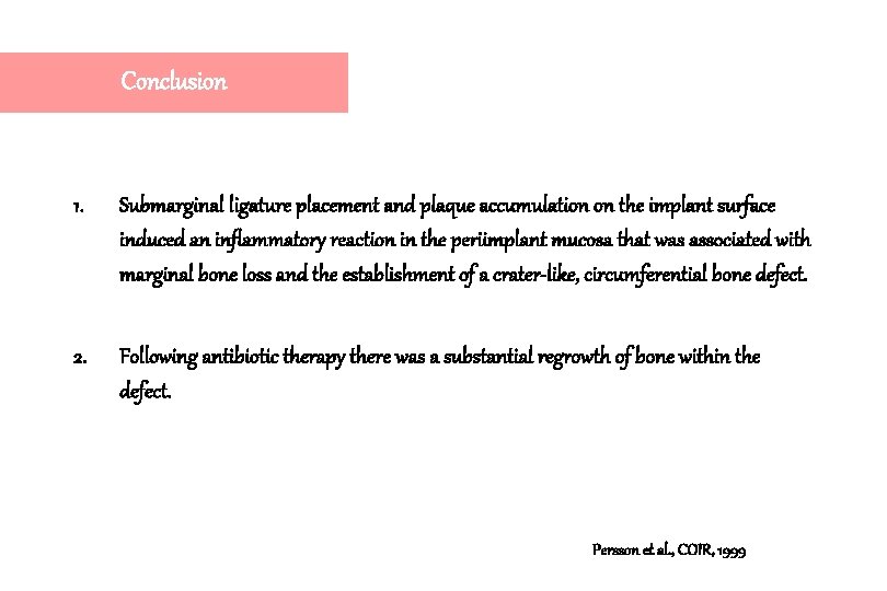
Conclusion 1. Submarginal ligature placement and plaque accumulation on the implant surface induced an inflammatory reaction in the periimplant mucosa that was associated with marginal bone loss and the establishment of a crater-like, circumferential bone defect. 2. Following antibiotic therapy there was a substantial regrowth of bone within the defect. Persson et al. , COIR, 1999
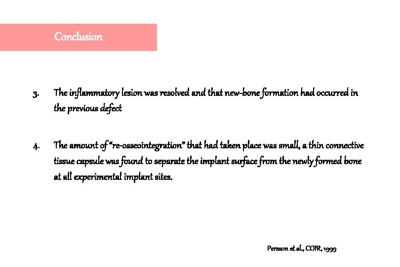
Conclusion 3. The inflammatory lesion was resolved and that new-bone formation had occurred in the previous defect 4. The amount of “re-osseointegration” that had taken place was small, a thin connective tissue capsule was found to separate the implant surface from the newly formed bone at all experimental implant sites. Persson et al. , COIR, 1999
Conclusion 5. The Oxytetracycline and Calcein blue markers were present in the coronal portions of the newly formed bone. This indicates that most of the bone formation occurred early during healing. 6. Both systemic antibiotics and local therapy with or without abrasive debridement of the implant surface predictably resolves a peri-implantitis but may not promote what has been called “reosseointegration” Persson et al. , COIR, 1999
Osseointegration following treatment of peri-implantitis and replacement of implant components An experimental study in the dog Persson L. G. Ericsson I. Berglundh T. Lindhe J. J. Clin. Periodontol. , 2001: 28: 258 -263
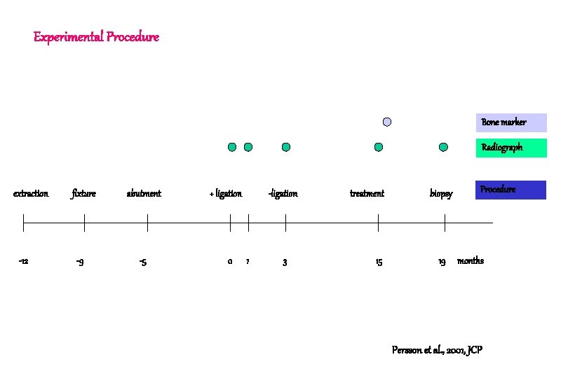
Experimental Procedure Bone marker Radiograph extraction -12 fixture -9 abutment -5 + ligation 0 -ligation 1 3 treatment 15 biopsy 19 Procedure months Persson et al. , 2001, JCP
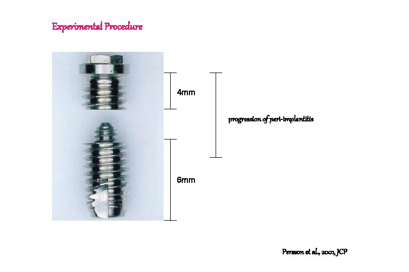
Experimental Procedure 4 mm progression of peri-implantitis 6 mm Persson et al. , 2001, JCP
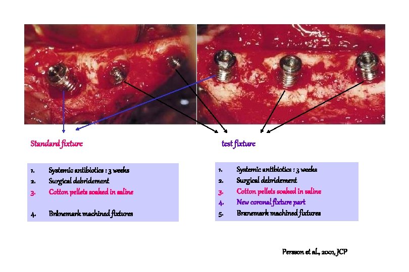
Standard fixture 1. 2. 3. Systemic antibiotics : 3 weeks Surgical debridement Cotton pellets soaked in saline 4. Brånemark machined fixtures test fixture 1. 2. 3. 4. 5. Systemic antibiotics : 3 weeks Surgical debridement Cotton pellets soaked in saline New coronal fixture part Branemark machined fixtures Persson et al. , 2001, JCP
Standard fixture test fixture C. T capsule Significant re-osseointegration failed. ICT gap Direct contact between the newly formed bone and the pristine implant surface Persson et al. , 2001, JCP
ICT gap (0. 5 -3 mm) represented the efforts by the host to close off bacteria present within the implant system. For obvious reasons no bone can form and no osseointegration take place in a contaminated and inflamed portion of the periimplant region. Persson et al. , 2001, JCP
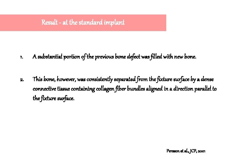
Result - at the standard implant 1. A substantial portion of the previous bone defect was filled with new bone. 2. This bone, however, was consistently separated from the fixture surface by a dense connective tissue containing collagen fiber bundles aligned in a direction parallel to the fixture surface. Persson et al. , JCP, 2001
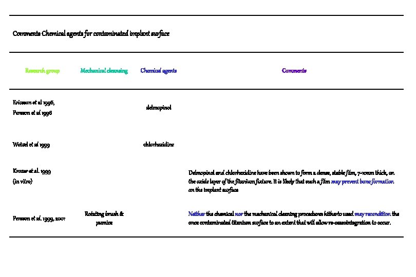
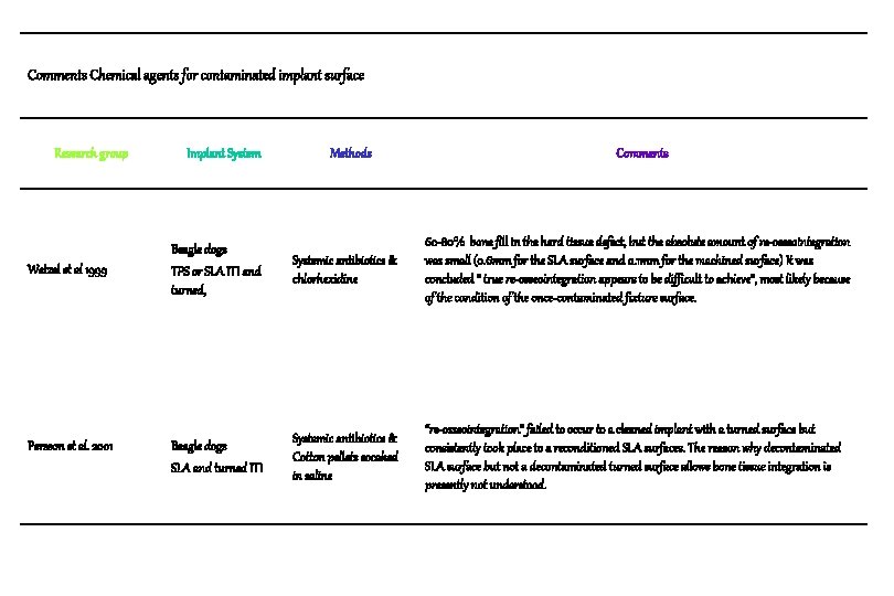
Comments Chemical agents for contaminated implant surface Research group Mechanical cleansing Ericsson et al 1996, Persson et al 1996 Comments delmopinol Wetzel et al 1999 chlorhexidine Krozer et al. 1999 (in vitro) Persson et al. 1999, 2001 Chemical agents Delmopinol and chlorhexidine have been shown to form a dense, stable film, 7 -10 nm thick, on the oxide layer of the fitanium fixture. It is likely that such a film may prevent bone formation on the implant surface Rotating brush & pumice Neither the chemical nor the mechanical cleaning procedures hitherto used may recondition the once contaminated titanium surface to an extent that will allow re-osseointegration to occur.
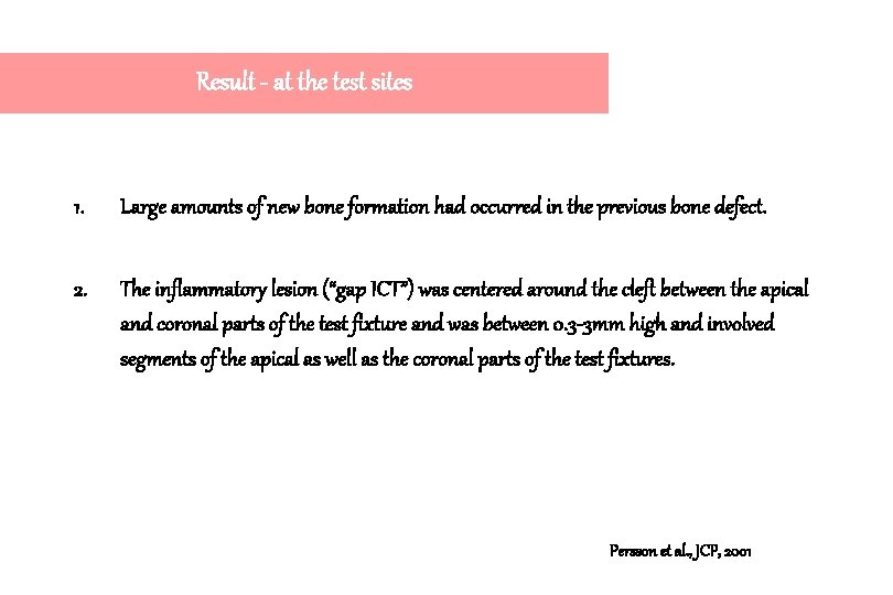
Result - at the test sites 1. Large amounts of new bone formation had occurred in the previous bone defect. 2. The inflammatory lesion (“gap ICT”) was centered around the cleft between the apical and coronal parts of the test fixture and was between 0. 3 -3 mm high and involved segments of the apical as well as the coronal parts of the test fixtures. Persson et al. , JCP, 2001
Result - at the test sites 3. The bone tissue found coronal to the “gap ICT” appeared to be in direct contact with the remaining, pristine part of the test fixture. 4. The % of mineralized bone that was in contact with the pristine part of the test fixtures was 34. 5 ± 20 %. The corresponding figure representing the 3 apical threads of the apical part of the test fixture was 69. 0 ± 9%. Persson et al. , JCP, 2001
Conclusion 1. Significant re-osseointegration failed to occur to implant surfaces exposed to bacterial contamination following traditional treatment of peri-implantitis lesions. 2. Such integration consistently occurred at sites where a pristine implant component was placed in the bone defect following surgical debridement. Persson et al. , JCP, 2001
Conclusion 3. Demonstrated that bone could form and osseointegrated take place to a pristine titanium surface even at sites where the distance between the coronal fixture and the walls of the bone defect was several mm. 4. In other words, there are reasons to suggest that it is not the dimensions of the bone defect per se but rather the quality of the titanium surface that determines whether osseointegration will occur Persson et al. , JCP, 2001
Conclusion 5. “Abutment ICT” represented the efforts by the host to close off bacteria present within the implant system. 6. For obvious reasons no bone can form and osseointegration does not take place in a contaminated and inflamed portion of the periimplant region. Persson et al. , JCP, 2001
General Consensus about Treatment of Periimplantitis It was suggested that re-osseointegration to a previously contaminated but cleaned and conditioned titanium surface was difficult/impossible. Ericsson et al. 1996, Persson et al. 1999
Re-osseointegration after treatment of peri-implantitis at different implant surfaces : An experimental study in the dog Leif G. Persson Tord Berglundh Lars Sennerby Jan Lindhe Clinical Oral Implants Research, 2001: 12: 595 -603
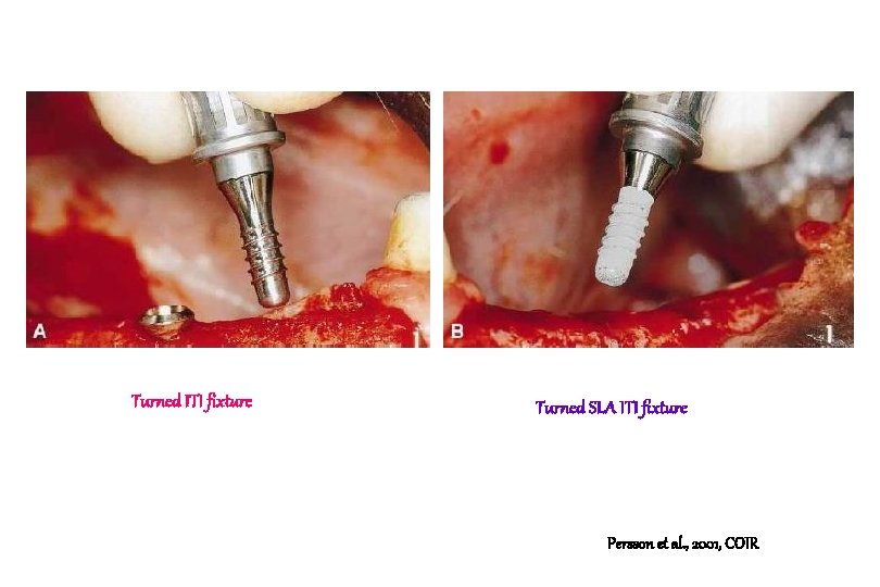
Turned ITI fixture Turned SLA ITI fixture Persson et al. , 2001, COIR
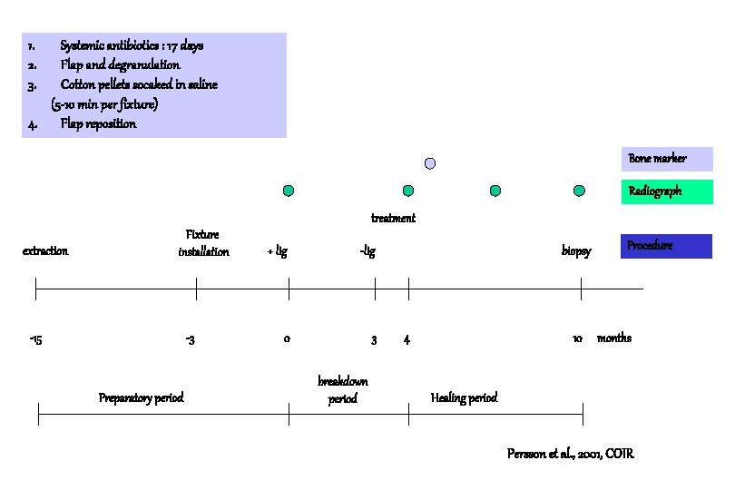
1. 2. 3. Systemic antibiotics : 17 days Flap and degranulation Cotton pellets socaked in saline (5 -10 min per fixture) 4. Flap reposition Bone marker Radiograph treatment extraction Fixture installation -15 -3 Preparatory period + lig -lig 0 3 breakdown period biopsy 4 10 Procedure months Healing period Persson et al. , 2001, COIR
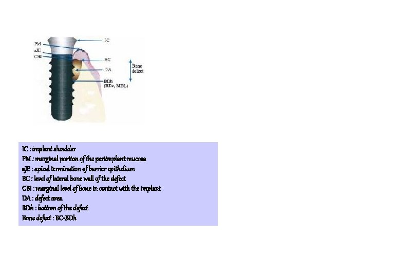
IC : implant shoulder PM : marginal portion of the periimplant mucosa a. JE : apical termination of barrier epithelium BC : level of lateral bone wall of the defect CBI : marginal level of bone in contact with the implant DA : defect area BDh : bottom of the defect Bone defect : BC-BDh
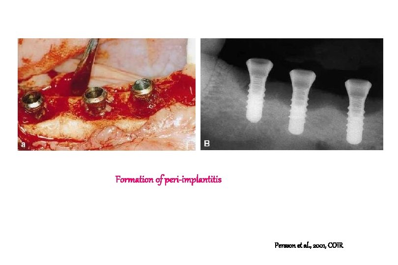
Formation of peri-implantitis Persson et al. , 2001, COIR
Turned ITI fixture a. b. c. Apical and lateral borders of the bone defect (arrows) Most coronal bone in contact with the implant (arrow) A connective tissue is separating the bone from the implant surface. Persson et al. , 2001, COIR
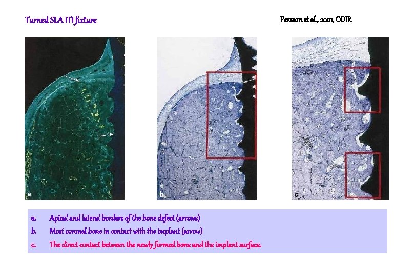
Turned SLA ITI fixture a. b. c. Apical and lateral borders of the bone defect (arrows) Most coronal bone in contact with the implant (arrow) The direct contact between the newly formed bone and the implant surface. Persson et al. , 2001, COIR
Higher magnification (x 100). Note that direct contact was established between the newly formed bone and the implant surface. Persson et al. , 2001, COIR
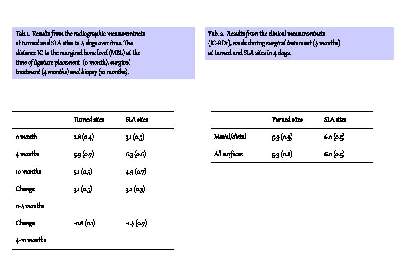
Tab. 1. Results from the radiographic measuremtnets at turned and SLA sites in 4 dogs over time. The distance IC to the marginal bone level (MBL) at the time of ligature placement (0 month), surgical treatment (4 months) and biopsy (10 months). Turned sites SLA sites 0 month 2. 8 (0. 4) 3. 1 (0. 5) 4 months 5. 9 (0. 7) 6. 3 (0. 6) 10 months 5. 1 (0. 5) 4. 9 (0. 7) Change 3. 1 (0. 5) 3. 2 (0. 3) -0. 8 (0. 1) -1. 4 (0. 7) 0 -4 months Change 4 -10 months Tab. 2. Results from the clinical measuremtnets (IC-BDc), made during surgical tretament (4 months) at turned and SLA sites in 4 dogs. Turned sites SLA sites Mesial/distal 5. 9 (0. 9) 6. 0 (0. 5) All surfaces 5. 9 (0. 8) 6. 0 (0. 5)
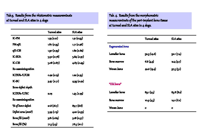
Tab. 3. Results from the rhistometric measuremtnets at turned and SLA sites in 4 dogs Tab. 4. Results from the morphometric measuremtnets of the peri-implant bone tissue at turned and SLA sites in 4 dogs. Turned sites SLA sites IC-PM 1. 33 (0. 21) 1. 31 (0. 45) PM-a. JE 1. 87 (0. 35) 1. 71 (0. 46) a. JE-CBI 1. 90 (0. 39) 1. 62 (0. 62) IC-BDh 5. 50 (0. 78) 5. 84 (0. 37) IC-CBI 5. 08 (0. 67) 4. 63 (0. 49) Re-osseointegration IC/BDh-IC/CBI 0. 42 (0. 13) 1. 22 (0. 35) IC-BC 3. 47 (0. 71) 4. 39 (0. 42) 2. 03 1. 45 (0. 33) Bone defect depth IC/BDh-IC/BC Re-osseointegration % of bone defect 21. 8 (16. 7) 83. 7 (8. 6) Defect area (mm²) 5. 34 (1. 19) 4. 20 (0. 93) Bone fill (mm²) 3. 81 (0. 84) 3. 18 (0. 57) Bone fill (%) 71. 5 (3. 9) 76. 5 (10. 1) Turned sites SLA sites Lamellar bone 50. 5 (14. 6) 50. 1 (7. 4) Bone marrow 6. 8 (4. 3) 12. 4 (3. 7) Woven bone 42. 6 (13. 4) 37. 5 (5. 1) Lamellar bone 89. 1 (3. 5) 85. 8 (8. 2) Bone marrow 10. 9 (3. 5) 14. 2 (6. 2) Woven bone 0 0 Regenerated bone “Old bone”
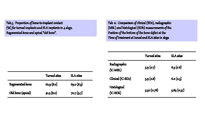
Tab. 5. Proportion of bone-to-implant contact (%) for turned implants and SLA implants in 4 dogs. Regenerated bone and apical “old bone”. Turned sites SLA sites Regenerated bone 62. 9 (8. 0) 69. 0 (8. 3) Old bone (apical) 41. 9 (8. 0) 70. 7 (9. 7) Tab. 6. Comparison of clinical (BDc), radiographic (MBL) and histological (BDh) measurements of the Position of the bottom of the bone defect at the Time of treatment at tuned and SLA sites in dogs. Turned sites SLA sites Radiographic (IC-MBL) 5. 9 (0. 7) 6. 3 (0. 6) Clinical (IC-BDc) 5. 9 (0. 8) 6. 0 (0. 5) Histological (IC-BDh) 5. 50 (0. 78) 5. 84 (0. 37)
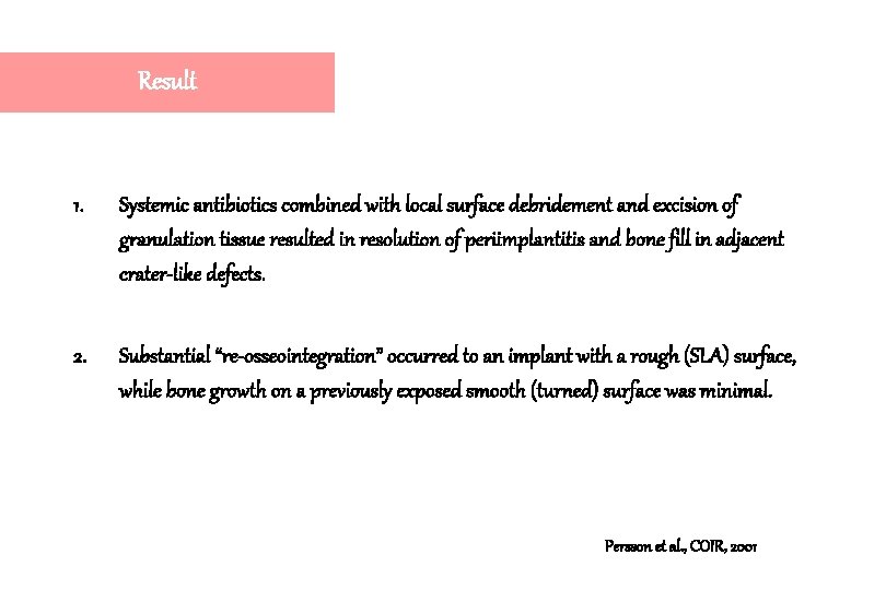
Result 1. Systemic antibiotics combined with local surface debridement and excision of granulation tissue resulted in resolution of periimplantitis and bone fill in adjacent crater-like defects. 2. Substantial “re-osseointegration” occurred to an implant with a rough (SLA) surface, while bone growth on a previously exposed smooth (turned) surface was minimal. Persson et al. , COIR, 2001
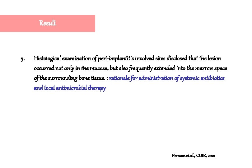
Result 3. Histological examination of peri-implantitis involved sites disclosed that the lesion occurred not only in the mucosa, but also frequently extended into the marrow space of the surrounding bone tissue. : rationale for administration of systemic antibiotics and local antimicrobial therapy Persson et al. , COIR, 2001
Comments Chemical agents for contaminated implant surface Research group Wetzel et al 1999 Persson et al. 2001 Implant System Methods Comments Beagle dogs TPS or SLA ITI and turned, Systemic antibiotics & chlorhexidine 60 -80% bone fill in the hard tissue defect, but the absolute amount of re-osseointegration was small (0. 6 mm for the SLA surface and 0. 1 mm for the machined surface) It was concluded “ true re-osseointegration appears to be difficult to achieve”, most likely because of the condition of the once-contaminated fixture surface. Beagle dogs SLA and turned ITI Systemic antibiotics & Cotton pellets socaked in saline “re-osseointegration” failed to occur to a cleaned implant with a turned surface but consistently took place to a reconditioned SLA surfaces. The reason why decontaminated SLA surface but not a decontaminated turned surface allows bone tissue integration is presently not understood.
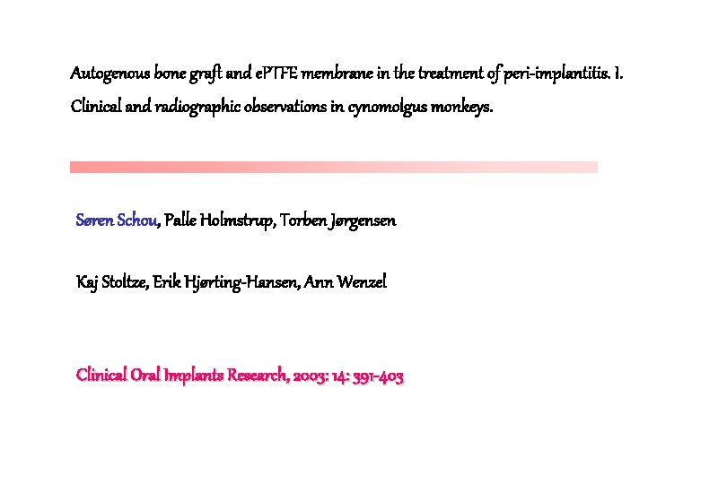
Autogenous bone graft and e. PTFE membrane in the treatment of peri-implantitis. I. Clinical and radiographic observations in cynomolgus monkeys. Søren Schou, Palle Holmstrup, Torben Jørgensen Kaj Stoltze, Erik Hjørting-Hansen, Ann Wenzel Clinical Oral Implants Research, 2003: 14: 391 -403
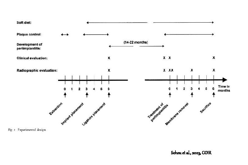
Schou et al. , 2003, COIR
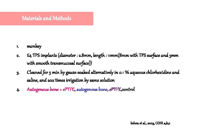
Materials and Methods 1. monkey 2. 64 TPS implants (diameter : 2. 8 mm, length : 11 mm(8 mm with TPS surface and 3 mm with smooth transmucosal surface)) 3. Cleaned for 5 min by gauze soaked alternatively in 0. 1 % aqueous chlorhexidine and saline, and 20 x times irrigation by same solution 4. Autogenous bone + e. PTFE, autogenous bone, e. PTFE, control Schou et al. , 2003, COIR a, b, c
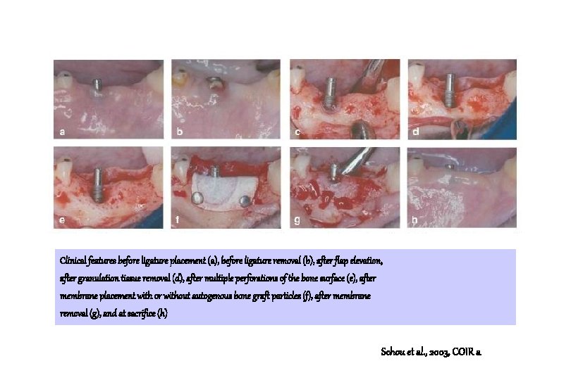
Clinical features before ligature placement (a), before ligature removal (b), after flap elevation, after granulation tissue removal (d), after multiple perforations of the bone surface (e), after membrane placement with or without autogenous bone graft particles (f), after membrane removal (g), and at sacrifice (h) Schou et al. , 2003, COIR a
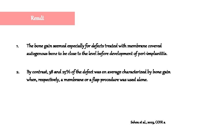
Result 1. The bone gain seemed especially for defects treated with membrane covered autogenous bone to be close to the level before development of peri-implantitis. 2. By contrast, 38 and 25% of the defect was on average characterized by bone gain when, respectively, a membrane or a flap procedure was used alone. Schou et al. , 2003, COIR a
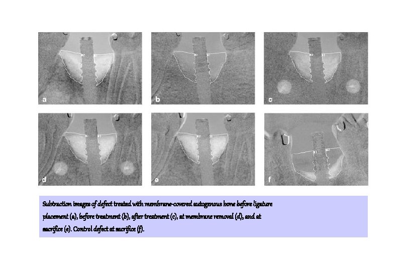
Subtraction images of defect treated with membrane-covered autogenous bone before ligature placement (a), before treatment (b), after treatment (c), at membrane removal (d), and at sacrifice (e). Control defect at sacrifice (f).
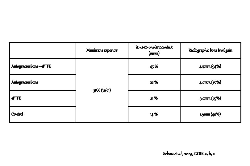
Bone-to-implant contact (mean) Radiographic bone level gain Autogenous bone + e. PTFE 45 % 4. 7 mm (94%) Autogenous bone 22 % 4. 0 mm (80%) e. PTFE 21 % 3. 0 mm (65%) Control 14 % 1. 9 mm (40%) Membrane exposure 38% (12/61) Schou et al. , 2003, COIR a, b, c
Conclusion 1. Considerable bone regeneration was identified within defects treated with autogenous bone with or without membrane coverage. Schou et al. , 2003, COIR a
Autogenous bone graft and e. PTFE membrane in the treatment of peri-implantitis. II. Stereologic and histologic observations in cynomolgus monkeys. Søren Schou, Palle Holmstrup, Lene Theil Skovgaard, Kaj Stoltze, Erik Hjørting-Hansen, Hans Jørgen G. Gundersen Clinical Oral Implants Research, 2003: 14: 404 -411
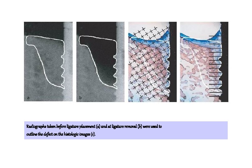
Radiographs taken before ligature placement (a) and at ligature removal (b) were used to outline the defect on the histologic images (c).
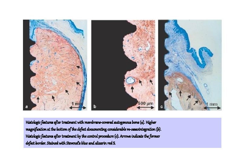
Histologic features after treatment with membrane-covered autogenous bone (a). Higher magnification at the bottom of the defect documenting considerable re-osseointegration (b). Histologic features after treatment by the control procedure (c). Arrows indicate the former defect border. Stained with Stevenel’s blue and alizarin red S.
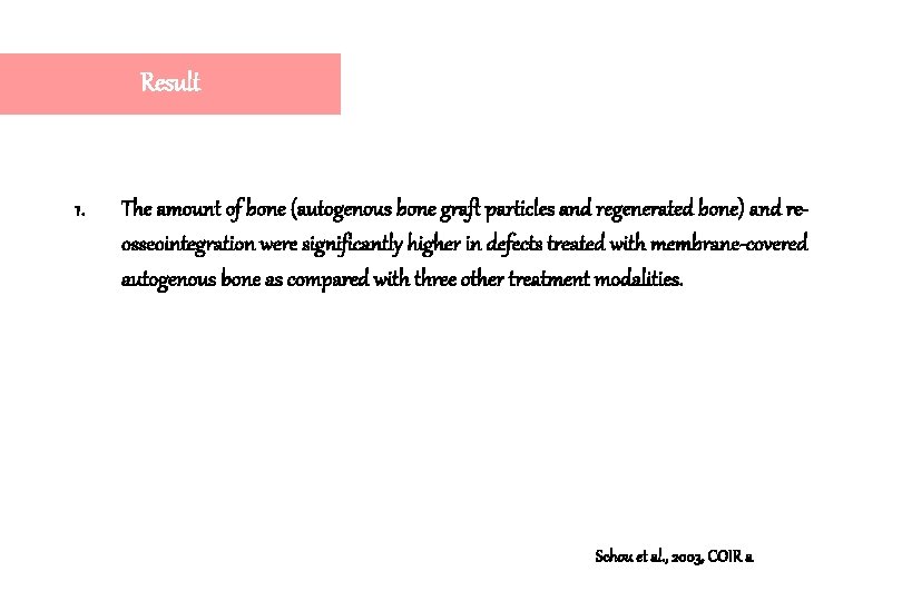
Result 1. The amount of bone (autogenous bone graft particles and regenerated bone) and reosseointegration were significantly higher in defects treated with membrane-covered autogenous bone as compared with three other treatment modalities. Schou et al. , 2003, COIR a
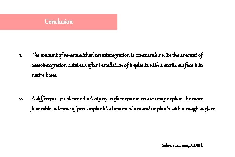
Conclusion 1. The amount of re-established osseointegration is comparable with the amount of osseointegration obtained after installation of implants with a sterile surface into native bone. 2. A difference in osteoconductivity by surface characteristics may explain the more favorable outcome of peri-implantitis treatment around implants with a rough surface. Schou et al. , 2003, COIR b
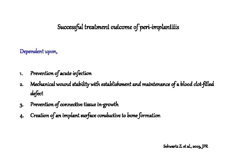
Successful treatment outcome of peri-implantitis Dependent upon, 1. Prevention of acute infection 2. Mechanical wound stability with establishment and maintenance of a blood clot-filled defect 3. Prevention of connective tissue in-growth 4. Creation of an implant surface conductive to bone formation Schwartz Z. et al. , 2003, JPR
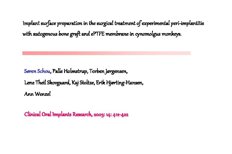
Implant surface preparation in the surgical treatment of experimental peri-implantitis with autogenous bone graft and e. PTFE membrane in cynomolgus monkeys. Søren Schou, Palle Holmstrup, Torben Jørgensen, Lene Theil Skovgaard, Kaj Stoltze, Erik Hjørting-Hansen, Ann Wenzel Clinical Oral Implants Research, 2003: 14: 412 -422
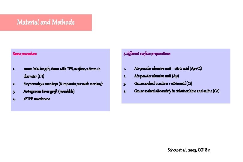
Material and Methods Same procedure 4 different surface preparations 1. 11 mm total length, 8 mm with TPS, surface, 2. 8 mm in 1. Air-powder abrasive unit + citric acid (Ap+Ci) diameter (ITI) 2. Air-powder abrasive unit (Ap) 2. 8 cynomolgus monkeys (8 implants per each monkey) 3. Gauze soaked in saline + citric acid (Ci) 3. Autogenous bone graft (mandible) 4. Gauze soaked alternately in chlorhexidine and saline (Ch) 4. e. PTFE membrane Schou et al. , 2003, COIR c
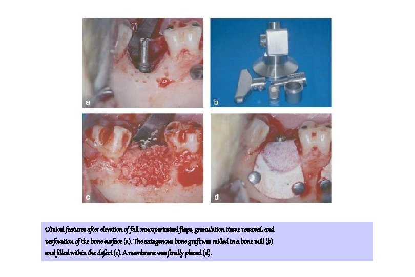
Clinical features after elevation of full mucoperiosteal flaps, granulation tissue removal, and perforation of the bone surface (a). The autogenous bone graft was milled in a bone mill (b) and filled within the defect (c). A membrane was finally placed (d).
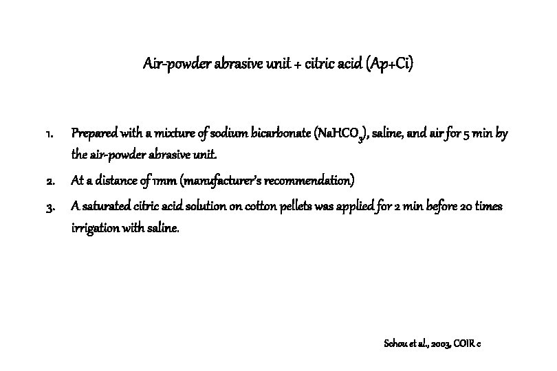
Air-powder abrasive unit + citric acid (Ap+Ci) 1. Prepared with a mixture of sodium bicarbonate (Na. HCO 3), saline, and air for 5 min by the air-powder abrasive unit. 2. At a distance of 1 mm (manufacturer’s recommendation) 3. A saturated citric acid solution on cotton pellets was applied for 2 min before 20 times irrigation with saline. Schou et al. , 2003, COIR c
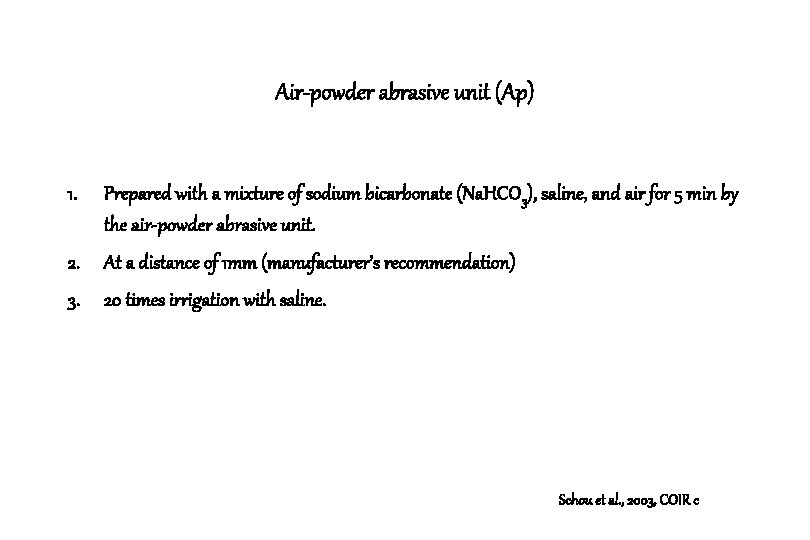
Air-powder abrasive unit (Ap) 1. Prepared with a mixture of sodium bicarbonate (Na. HCO 3), saline, and air for 5 min by the air-powder abrasive unit. 2. At a distance of 1 mm (manufacturer’s recommendation) 3. 20 times irrigation with saline. Schou et al. , 2003, COIR c
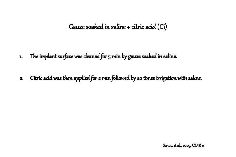
Gauze soaked in saline + citric acid (Ci) 1. The implant surface was cleaned for 5 min by gauze soaked in saline. 2. Citric acid was then applied for 2 min followed by 20 times irrigation with saline. Schou et al. , 2003, COIR c
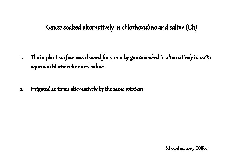
Gauze soaked alternatively in chlorhexidine and saline (Ch) 1. The implant surface was cleaned for 5 min by gauze soaked in alternatively in 0. 1% aqueous chlorhexidine and saline. 2. Irrigated 20 times alternatively by the same solution Schou et al. , 2003, COIR c
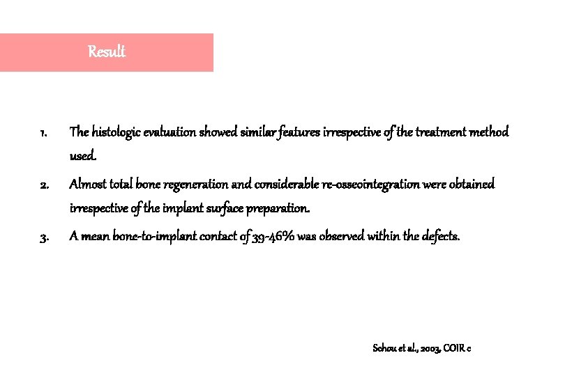
Result 1. The histologic evaluation showed similar features irrespective of the treatment method used. 2. Almost total bone regeneration and considerable re-osseointegration were obtained irrespective of the implant surface preparation. 3. A mean bone-to-implant contact of 39 -46% was observed within the defects. Schou et al. , 2003, COIR c
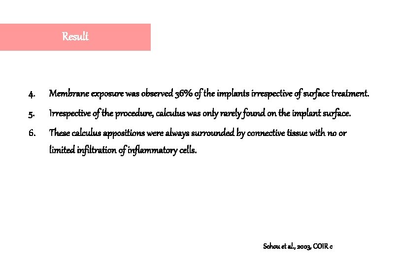
Result 4. Membrane exposure was observed 36% of the implants irrespective of surface treatment. 5. Irrespective of the procedure, calculus was only rarely found on the implant surface. 6. These calculus appositions were always surrounded by connective tissue with no or limited infiltration of inflammatory cells. Schou et al. , 2003, COIR c
Instrumentations for the treatment of peri-implantitis 1. Titanium surface were severely damaged after the use of metal curettes for hand scaling and conventional sonic/ ultrasonic scalers. 2. Residues of nonmetallic soft scalers have been revealed on the titanium surface. Schou et al. , 2003, COIR c
Air-powder abrasive systems for peri-implantitis 1. Although increased implant surface roughness and retained powder particles have been observed, in most studies no or only minor surface changes were found. 2. The number of emphysema and pneumoparotitis cases induced by air-powder abrasive units is very low. Schou et al. , 2003, COIR c
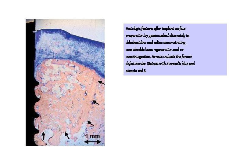
Histologic features after implant surface preparation by gauze soaked alternately in chlorhexidine and saline demonstrating considerable bone regeneration and reosseointegration. Arrows indicate the former defect border. Stained with Stevenel’s blue and alizarin red S.
Conclusion 1. The simplest method including gauze soaked alternately in chlorhexidine and saline should be the preferred implant surface preparation method in the surgical treatment of peri-implantitis involving autogenous bone graft and e. PTFE. 2. The use of chlorhexidine did not appear to jeopardize the re-establishment of osseointegration. Schou et al. , 2003, COIR c
Anorganic porous bovine-derived bone mineral (Bio. Oss) and e. PTFE membrane in the treatment of peri-implantitis in cynomolgus monkeys. Søren Schou, Palle Holmstrup, Torben Jørgensen, Lene Theil Skovgaard, Kaj Stoltze, Erik Hjørting-Hansen, Ann Wenzel Clinical Oral Implants Research, 2003: 14: 535 -547
Materials and Methods 1. 8 cynomolgus monkeys 2. 64 TPS implants (diameter : 2. 8 mm, length : 11 mm(8 mm with TPS surface and 3 mm with smooth transmucosal surface)) 3. Cleaned for 5 min by gauze soaked alternatively in 0. 1 % aqueous chlorhexidine and saline, and 20 x times irrigation by same solution 4. Bio. Oss + e. PTFE, Bio. Oss, e. PTFE, control Schou et al. , 2003, COIR a, b, c
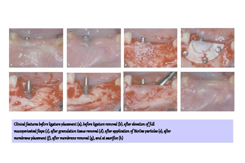
Clinical features before ligature placement (a), before ligature removal (b), after elevation of full mucoperiosteal flaps (c), after granulation tissue removal (d), after application of Bio. Oss particles (e), after membrane placement (f), after membrane removal (g), and at sacrifice (h)
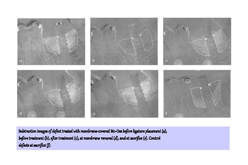
Subtraction images of defect treated with membrane-covered Bio-Oss before ligature placement (a), before treatment (b), after treatment (c), at membrane removal (d), and at sacrifice (e). Control defects at sacrifice (f).
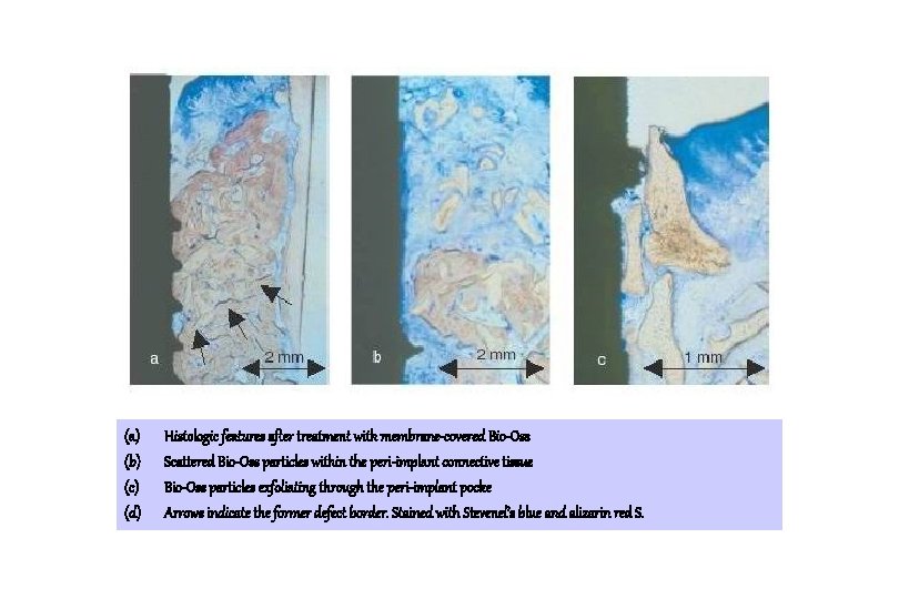
(a) (b) (c) (d) Histologic features after treatment with membrane-covered Bio-Oss Scattered Bio-Oss particles within the peri-implant connective tissue Bio-Oss particles exfoliating through the peri-implant pocke Arrows indicate the former defect border. Stained with Stevenel’s blue and alizarin red S.
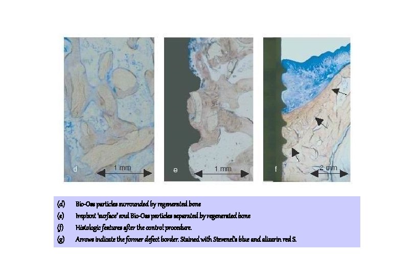
(d) (e) (f) (g) Bio-Oss particles surrounded by regenerated bone Implant ‘surface’ and Bio-Oss particles separated by regenerated bone Histologic features after the control procedure. Arrows indicate the former defect border. Stained with Stevenel’s blue and alizarin red S.
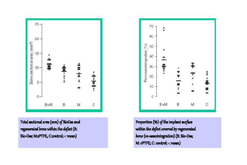
Total sectional area (mm) of Bio. Oss and regenerated bone within the defect (B: Bio-Oss; M: e. PTFE, C: control; -: mean) Proportion (%) of the implant surface within the defect covered by regenerated bone (re-osseointegration) (B: Bio-Oss; M: e. PTFE; C: control; -: mean)
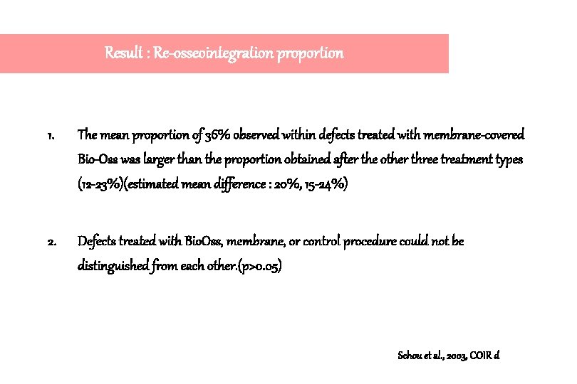
Result : Re-osseointegration proportion 1. The mean proportion of 36% observed within defects treated with membrane-covered Bio-Oss was larger than the proportion obtained after the other three treatment types (12 -23%)(estimated mean difference : 20%, 15 -24%) 2. Defects treated with Bio. Oss, membrane, or control procedure could not be distinguished from each other. (p>0. 05) Schou et al. , 2003, COIR d
Result 1. It should be taken into consideration that the radiopacity within the occlusal part of the defect is Bio. Oss particles surrounded by connective tissue and not by regenerated bone. 2. Extensive resorption of Bio. Oss particles within the peri-implant C. T. has been reported (Hämmerle et al. 1998), but in the present study neither osteoclast-like cells nor inflammatory cells were observed adjacent to Bio. Oss. Schou et al. , 2003, COIR d
Conclusion 1. The present study indicated that the combined use of Bio-Oss and membrane is preferable for the treatment of peri-implantitis. 2. Membrane-covered autogenous bone seems still most useful for the surgical treatment of per-implantitis. Schou et al. , 2003, COIR d
Osseointegration on implant surfaces previously contaminated with plaque. An experimental study in the dog Stavros G. Kolonidis, Stefan Renvert, Christopher H. F. Hämmerle, Niklaus P. Lang, David Harris, Noel Claffey Clinical Oral Implants Research, 2003: 14: 373 -380
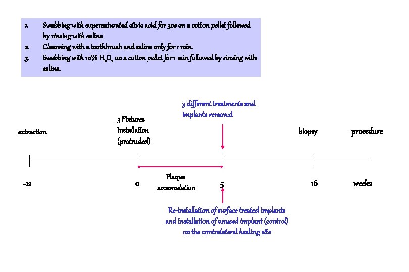
Materials and Methods 1. Labrador dog 2. 3 C. P. machined titanium implants (Nobel Biocare) 3. 3 different cleansing methods used. Kolonidis et al. , 2003, COIR
1. 2. 3. Swabbing with supersaturated citric acid for 30 s on a cotton pellet followed by rinsing with saline Cleansing with a toothbrush and saline only for 1 min. Swabbing with 10% H 2 O 2 on a cotton pellet for 1 min followed by rinsing with saline. extraction -12 3 Fixtures Installation (protruded) 0 3 different treatments and implants removed biopsy Plaque accumulation 5 Re-installation of surface treated implants and installation of unused implant (control) on the contralateral healing site 16 procedure weeks
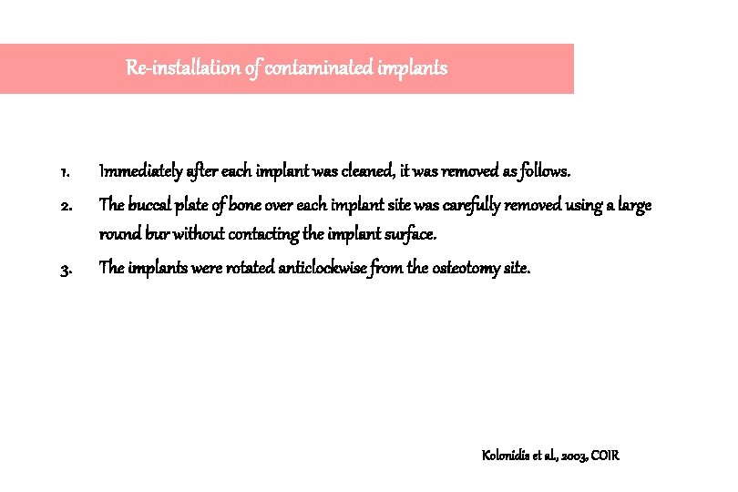
Re-installation of contaminated implants 1. Immediately after each implant was cleaned, it was removed as follows. 2. The buccal plate of bone over each implant site was carefully removed using a large round bur without contacting the implant surface. 3. The implants were rotated anticlockwise from the osteotomy site. Kolonidis et al. , 2003, COIR
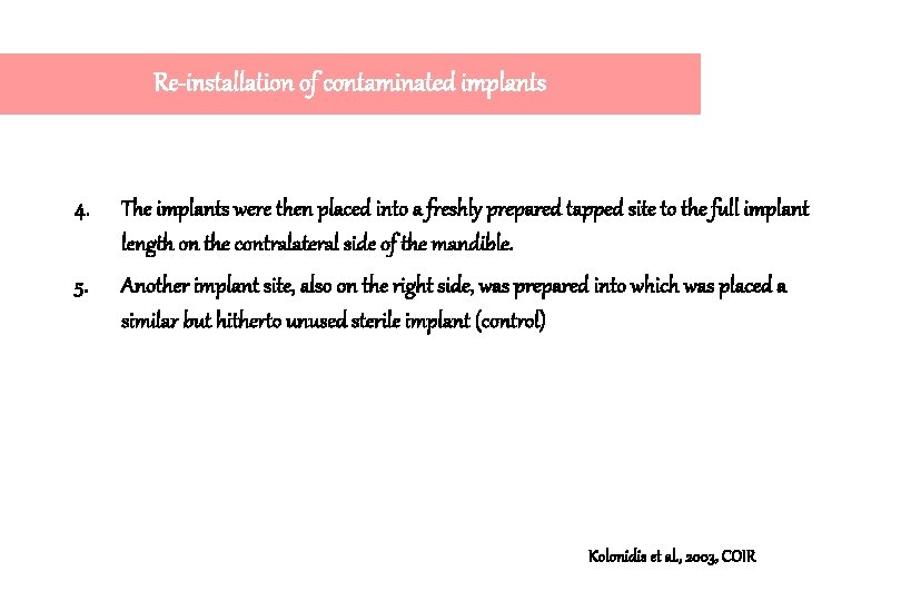
Re-installation of contaminated implants 4. The implants were then placed into a freshly prepared tapped site to the full implant length on the contralateral side of the mandible. 5. Another implant site, also on the right side, was prepared into which was placed a similar but hitherto unused sterile implant (control) Kolonidis et al. , 2003, COIR
Three implants partially inserted. Three implants exposed in the oral environment after flap repositioning. Kolonidis et al. , 2003, COIR
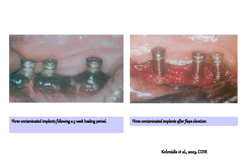
Three contaminated implants following a 5 week healing period. Three contaminated implants after flaps elevation Kolonidis et al. , 2003, COIR
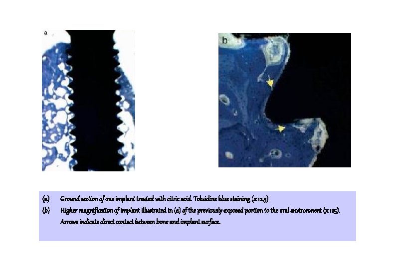
(a) (b) Ground section of one implant treated with citric acid. Toluidine blue staining (x 12. 5) Higher magnification of implant illustrated in (a) of the previously exposed portion to the oral environment (x 125). Arrows indicate direct contact between bone and implant surface.
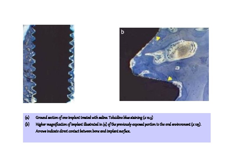
(a) (b) Ground section of one implant treated with saline. Toluidine blue staining (x 12. 5) Higher magnification of implant illustrated in (a) of the previously exposed portion to the oral environment (x 125). Arrows indicate direct contact between bone and implant surface.
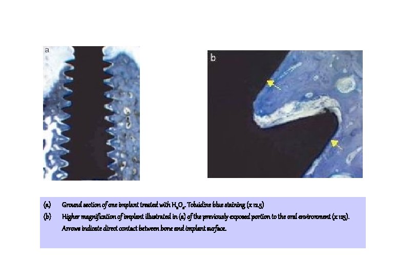
(a) (b) Ground section of one implant treated with H 2 O 2. Toluidine blue staining (x 12. 5) Higher magnification of implant illustrated in (a) of the previously exposed portion to the oral environment (x 125). Arrows indicate direct contact between bone and implant surface.
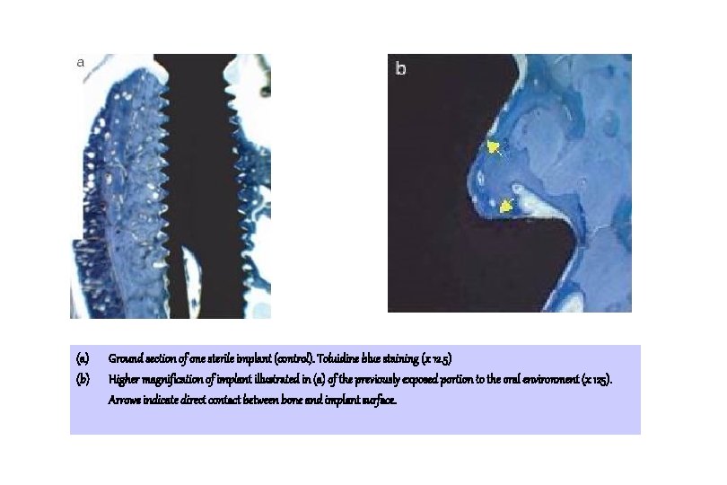
(a) (b) Ground section of one sterile implant (control). Toluidine blue staining (x 12. 5) Higher magnification of implant illustrated in (a) of the previously exposed portion to the oral environment (x 125). Arrows indicate direct contact between bone and implant surface.
Result 1. Osseointegration can indeed occur to a surfaces that were plaque contaminated and cleaned by different methods. 2. Moreover, the amount of osseointegration did not significantly differ between treatment modalities, a surprising finding considering that one of the modalities was a new sterile implant. Kolonidis et al. , 2003, COIR
Successful results of this experiment , its reasons ? 1. Ligature-induced peri-implantitis model produces defects of morphology that elements of clot adhesion, wound stability, and cellular migration/differentiation may affect the outcome in addition to any proposed effect of surface. 2. By minimising the distance between surrounding bone and implant surfaces, the effect of surface contamination followed by cleansing can more clearly be studied. Kolonidis et al. , 2003, COIR
Successful results of this experiment , its reasons ? 3. The possibility that friction during re-insertion may, to some degree, have had a cleansing effect of its own. 4. However, it is unlikely that this factor significantly altered the outcome as the more coronal aspects of the osteotomies were tapped before re-insertion of the implants and any such ‘self cleansing’ would therefore be applicable to the more apical areas. Kolonidis et al. , 2003, COIR
Conclusion : limitations of this experiment 1. A direct application of the results of this study into a human situation is inappropriate. 2. Small number of animals 3. The lack of a negative control, implants first contaminated but then inserted without a cleaning procedure. Kolonidis et al. , 2003, COIR
Histopathological observations of human periimplantitis lesions Tord Berglundh, Örn Gislason, Ulf Lekholm, Lars Sennerby and Jan Lindhe J. Clin. Periodontol. , 2004; 31: 341 -347
Definition of periimplantitis by Albrektsson & Isidor (1994) Condition that includes “inflammatory reactions in the periimplant tissues and loss of supporting bone around an implant in function.
Material and Methods 1. Soft tissue biopsy obtained from 12 implant sites in 6 patients. 2. Function between 4 and 21 years 3. Advanced bone loss 4. Clinical signs of severe inflammation, such as suppuration, swelling, and/or fistula formation 5. 7 of the 12 implants were found to be mobile at biopsy. Berglundh et al. JCP 2004
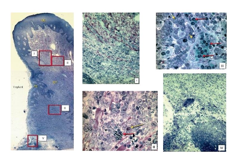
Results 1. The lesions that were included in biopsies from the implant failure and periimplantitis treatment groups (including mobile and non-mobile implants at removal) had similar histopathological characteristics. 2. In all specimens a large ICT occupied almost the entire connective tissue portion. Berglundh et al. JCP 2004
Results 3. The marginal aspect of the pocket epithelium was wide and exhibited rete ridges that projected into the infiltrated connective tissue. 4. The apical portion of the pocket epithelium, however, was frequently thin and ulcerated. Berglundh et al. JCP 2004
Results 5. In the marginal portion of the ICT comparatively large numbers of collagen fibers occurred together with numerous lymphocytes and plasma cells. 6. Few, but large vascular units occupied the central part of this marginal portion of the lesion, while numerous small vessels were present in an are lateral to the pocket epithelium. Berglundh et al. JCP 2004
Results 7. In the central and apical portions of the ICT, collagen fibers were few or in some specimens virtually absent, while inflammatory cells and vascular units dominated the lesion. Berglundh et al. JCP 2004
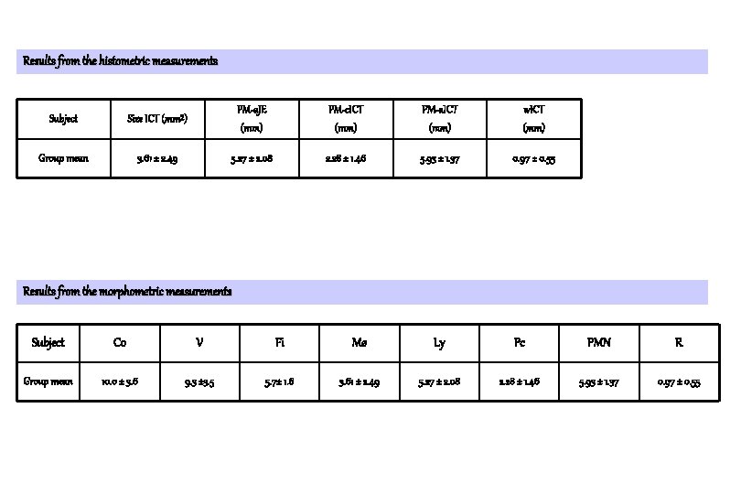
Results from the histometric measurements Subject Size ICT (mm²) PM-a. JE (mm) PM-c. ICT (mm) PM-a. ICT (mm) w. ICT (mm) Group mean 3. 61 ± 2. 49 5. 27 ± 2. 08 2. 28 ± 1. 46 5. 93 ± 1. 37 0. 97 ± 0. 55 Results from the morphometric measurements Subject Co V Fi Mø Ly Pc PMN R Group mean 10. 0 ± 3. 6 9. 3 ± 3. 5 5. 7± 1. 6 3. 61 ± 2. 49 5. 27 ± 2. 08 2. 28 ± 1. 46 5. 93 ± 1. 37 0. 97 ± 0. 55
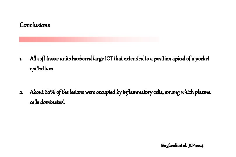
Conclusions 1. All soft tissue units harbored large ICT that extended to a position apical of a pocket epithelium 2. About 60% of the lesions were occupied by inflammatory cells, among which plasma cells dominated. Berglundh et al. JCP 2004
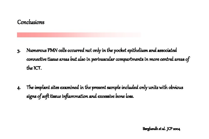
Conclusions 3. Numerous PMN cells occurred not only in the pocket epithelium and associated connective tissue areas but also in perivascular compartments in more central areas of the ICT. 4. The implant sites examined in the present sample included only units with obvious signs of soft tissue inflammation and excessive bone loss. Berglundh et al. JCP 2004
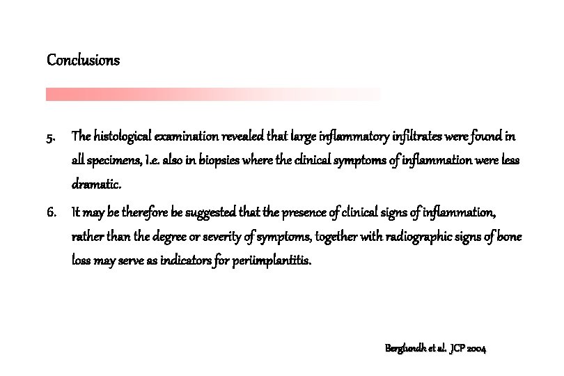
Conclusions 5. The histological examination revealed that large inflammatory infiltrates were found in all specimens, I. e. also in biopsies where the clinical symptoms of inflammation were less dramatic. 6. It may be therefore be suggested that the presence of clinical signs of inflammation, rather than the degree or severity of symptoms, together with radiographic signs of bone loss may serve as indicators for periimplantitis. Berglundh et al. JCP 2004
Conclusions 7. The presence of inflammatory lesions in the periimplant soft tissues may not have been influenced by implant mobility. Berglundh et al. JCP 2004
Berglundh et al. (2004) vs Esposito et al. (2000) 1. In 9 out of 10 implant sites examined by Esposito et al. (2000) there were no clinical signs of inflammation, i. e. redness, swelling or suppuration. 2. The term “implant failure” may not describe a periimplantitis condition similar to the one examined in Berglundh et al. (2004) 3. May be related to apparent variations in cause for failures.
Implant failure and Piattelli et al. (1998) 1. In their study particular attention was paid to a group of implants that were removed due to mobility. 2. The authors reported that such implants were surrounded by a “dense fibrous connective tissue” and that no inflammatory infiltrate was present.
Spontaneous progression of experimentally induced periimplantitis. Zitzmann N. U. , Berglundh T. , Ericsson I. , Lindhe J. J. Clin. Periodontol. 2004
Experimental peri-implantitis induced by cotton ligatures 1. Dog experiments 2. 1 month after the removal of such ligatures, a large inflammatory cell infiltrate (ICT) resided in the periimplant mucosa (PM) and that the apical portion of the lesion was close to or extended into the marginal bone. Lindhe et al. , COIR 1992
Experimental peri-implantitis induced by cotton ligatures 1. Dog experiments 2. 3 months after the removal of such ligatures in “experimental periimplantitis”, the ICT was in most sites separated from the bone by a dense collar of fibrous connective tissue. 3. In some sites, however, the tissue destruction continued and the extensive loss of bone had caused exfoliation of the implants. 4. The reason why, in some animals and sites, the periimplantitis lesions became encapsulated while in other sites the inflammatory condition progressed, is currently not understood. Marinello et al. , JCP 1995
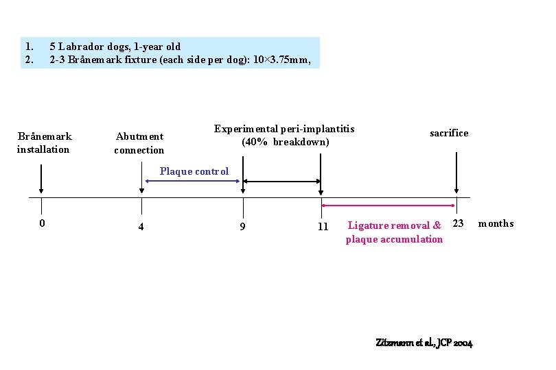
1. 2. 5 Labrador dogs, 1 -year old 2 -3 Brånemark fixture (each side per dog): 10× 3. 75 mm, Brånemark installation Abutment connection Experimental peri-implantitis (40% breakdown) sacrifice Plaque control 0 4 9 11 Ligature removal & 23 plaque accumulation Zitzmann et al. , JCP 2004 months
Materials and methods 1. 5 Labrador dogs, 1 year old 2. 22 Bränemark standard fixtures 3. Ligature-induced periimplantitis : changed once every 2 weeks during a 2 -month period and then removed. 4. Once a day, 5 days a week, toothbrushing with dentfrice 5. 2 dogs were assigned for treatment of periimplantitis (Persson et al. 2001)while 3 remaining dogs were sacrificed. Zitzmann et al. , JCP 2004
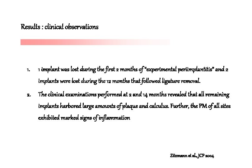
Results : clinical observations 1. 1 implant was lost during the first 2 months of “experimental periimplantitis” and 2 implants were lost during the 12 months that followed ligature removal. 2. The clinical examinations performed at 2 and 14 months revealed that all remaining implants harbored large amounts of plaque and calculus. Further, the PM of all sites exhibited marked signs of inflammation Zitzmann et al. , JCP 2004
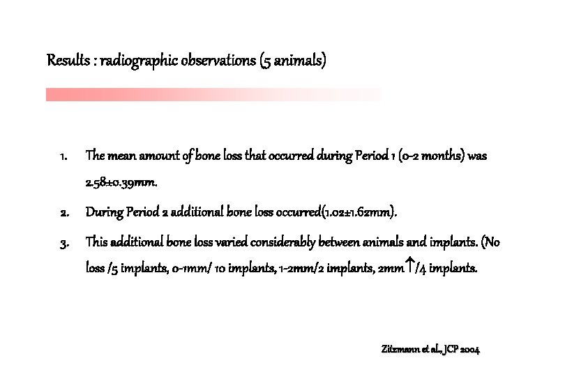
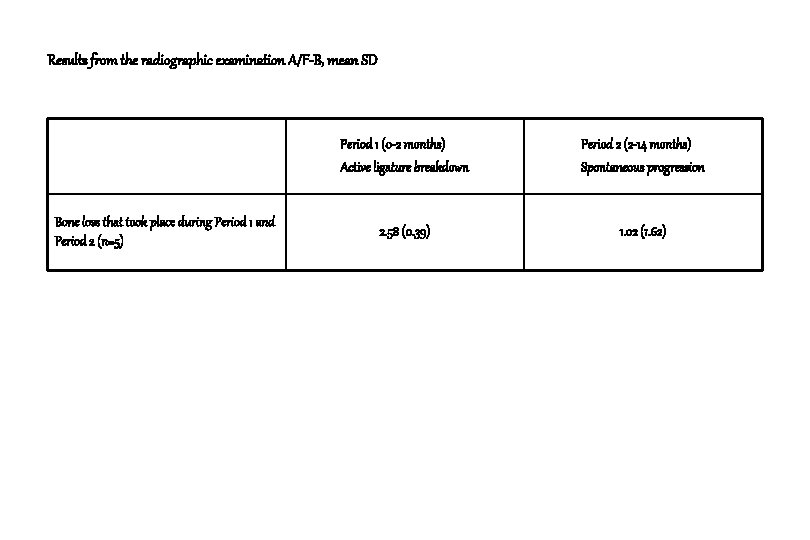
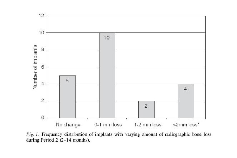
Results : radiographic observations (5 animals) 1. The mean amount of bone loss that occurred during Period 1 (0 -2 months) was 2. 58± 0. 39 mm. 2. During Period 2 additional bone loss occurred(1. 02± 1. 62 mm). 3. This additional bone loss varied considerably between animals and implants. (No loss /5 implants, 0 -1 mm/ 10 implants, 1 -2 mm/2 implants, 2 mm /4 implants. Zitzmann et al. , JCP 2004
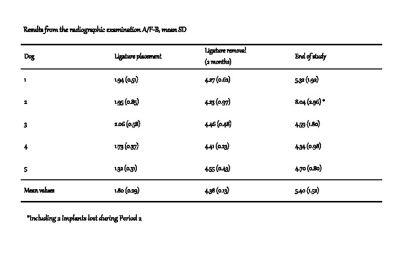
Results from the radiographic examination A/F-B, mean SD Dog Ligature placement Ligature removal (2 months) End of study 1 1. 94 (0. 51) 4. 27 (0. 62) 5. 32 (1. 92) 2 1. 95 (0. 85) 4. 23 (0. 97) 8. 04 (2. 96) * 3 2. 06 (0. 58) 4. 46 (0. 48) 4. 59 (1. 80) 4 1. 73 (0. 37) 4. 41 (0. 23) 4. 34 (0. 98) 5 1. 32 (0. 31) 4. 55 (0. 43) 4. 70 (0. 80) Mean values 1. 80 (0. 29) 4. 38 (0. 13) 5. 40 (1. 52) *Including 2 implants lost during Period 2
Results from the radiographic examination A/F-B, mean SD Bone loss that took place during Period 1 and Period 2 (n=5) Period 1 (0 -2 months) Active ligature breakdown Period 2 (2 -14 months) Spontaneous progression 2. 58 (0. 39) 1. 02 (1. 62)
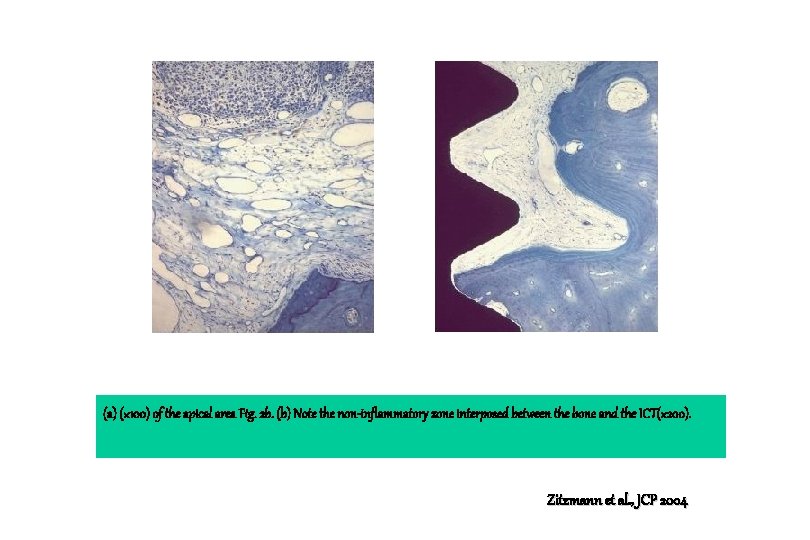
Results : histological observations (3 animals) 1. A ulcerated pocket epithelium separated the infiltrated connective tissue from plaque and pus in the pocket area. 2. The ICT area (1) included a large number of vascular structures, (2) was almost devoid of collagen and fibroblasts, and (3) was in an apical direction separated from bone tissue by a dense connective tissue. Zitzmann et al. , JCP 2004
Results : histological observations (3 animals) 3. This connective tissue contained large amounts of fibroblasts and collagen but no or only scattered inflammatory cells. Zitzmann et al. , JCP 2004
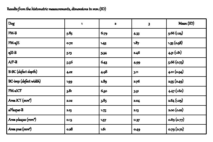
Results from the histometric measurements, dimensions in mm (SD) Dog 1 2 3 Mean (SD) PM-B 5. 85 6. 79 4. 33 5. 66 (1. 24) PM-a. JE 0. 72 1. 45 1. 87 1. 35 (0. 58) a. JE-B 5. 13 5. 34 2. 46 4. 31 (1. 61) A/F-B 5. 56 6. 43 4. 99 5. 66 (0. 73) B-BC (defect depth) 4. 22 4. 98 3. 11 4. 10 (0. 94) BC-imp (defect width) 1. 99 2. 89 2. 76 2. 55 (0. 49) PM-a. ICT 3. 81 6. 30 3. 31 4. 47 (1. 60) Area ICT (mm 2) 2. 02 3. 85 2. 04 2. 64 (1. 05) a. Plaque-B 2. 13 1. 75 2. 13 2. 00 (0. 22) Area plaque (mm 2) 0. 13 1. 57 0. 37 0. 69 (0. 77) Area pus (mm 2) 0. 28 1. 61 0. 49 0. 79 (0. 72)
(a) M-D cross section of the periimplant tissues adjacent to the implant. PAS and toluidine blue, (× 16), (b) (× 50) A/F, PM, a. Plaque, a. JE, a. ICT, B and BC indicate the landmarks used for histometric measurements. Zitzmann et al. , JCP 2004
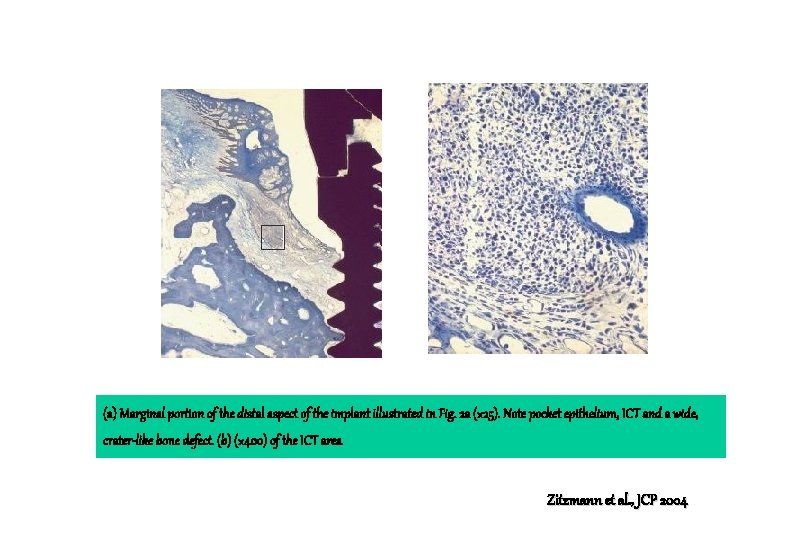
(a) Marginal portion of the distal aspect of the implant illustrated in Fig. 2 a (× 25). Note pocket epithelium, ICT and a wide, crater-like bone defect. (b) (× 400) of the ICT area Zitzmann et al. , JCP 2004
(a) (× 100) of the apical area Fig. 2 b. (b) Note the non-inflammatory zone interposed between the bone and the ICT(× 200). Zitzmann et al. , JCP 2004
Conclusion 1. 16 out of 21 implants exhibited varying amounts of additional bone loss during the 12 month (Period 2) that followed ligature removal. 2. The mucosa of all sites harbored large inflammatory lesions that extended apically of the pocket epithelium, and that this inflammatory cell infiltrate was consistently separated from the periimplant bone by a zone of apparently non-inflamed (non-infiltrated) connective tissue. Zitzmann et al. , JCP 2004
Conclusion 3. In the interval between 0 and 2 months about 2. 5 -3 mm of the marginal bone was lost. 4. It is suggested that the mechanical separation of the attachment between the mucosa and the implant , and the buildup of plaque in this submarginal location initiated an inflammatory reaction that involved not only the mucosa but also the periimplant bone. Zitzmann et al. , JCP 2004
Conclusion 5. The observation that the progressive breakdown of the periimplant bone during Period 2 continued in some but not all implants sites, is in agreement with findings reported by Marinello et al. (1995). Zitzmann et al. , JCP 2004
Conclusion 6. The reason why some periimplantitis lesions are associated with extensive and others with minor bone loss is currently not understood, but may be related to differences between implant sites regarding the submarginal microbiota, or the quality of the host’s response to the infection. Zitzmann et al. , JCP 2004
Conclusion 7. At the end of Period 2, a zone of normal connective tissue consistently separated the inflammatory lesion from the marginal bone. 8. At the time of biopsy, there were no signs of ongoing bone resorption. No or only isolated osteoclasts could be found on the surface of the marginal bone. . Zitzmann et al. , JCP 2004
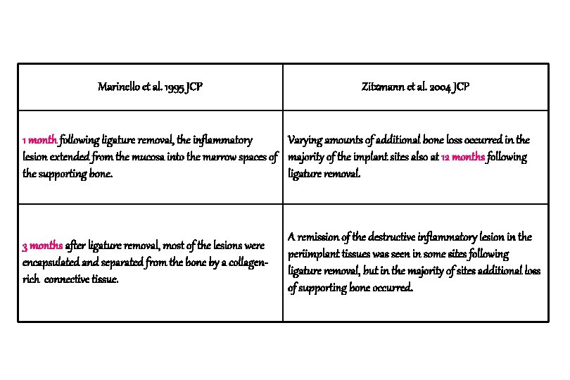
Marinello et al. 1995 JCP Zitzmann et al. 2004 JCP 1 month following ligature removal, the inflammatory Varying amounts of additional bone loss occurred in the lesion extended from the mucosa into the marrow spaces of majority of the implant sites also at 12 months following the supporting bone. ligature removal. 3 months after ligature removal, most of the lesions were encapsulated and separated from the bone by a collagenrich connective tissue. A remission of the destructive inflammatory lesion in the periimplant tissues was seen in some sites following ligature removal, but in the majority of sites additional loss of supporting bone occurred.
Implant stability during initiation and resolution of experimental periimplantitis : An experimental study in the dog Lars Sennerby, Leif G. Persson, Tord Berglundh T. , Ann Wennerberg, Jan Lindhe Clin. Impl. Dent. And Relat. Res ; 7(3), 2005 : 136 -140
The aim of this study 1. To study bone tissue and associated implant stability alterations that occurred during induction and resolution of peri-implantitis using resonance frequency analysis (RFA), radiography, and histology. Sennerby et al. CID & RR 2005
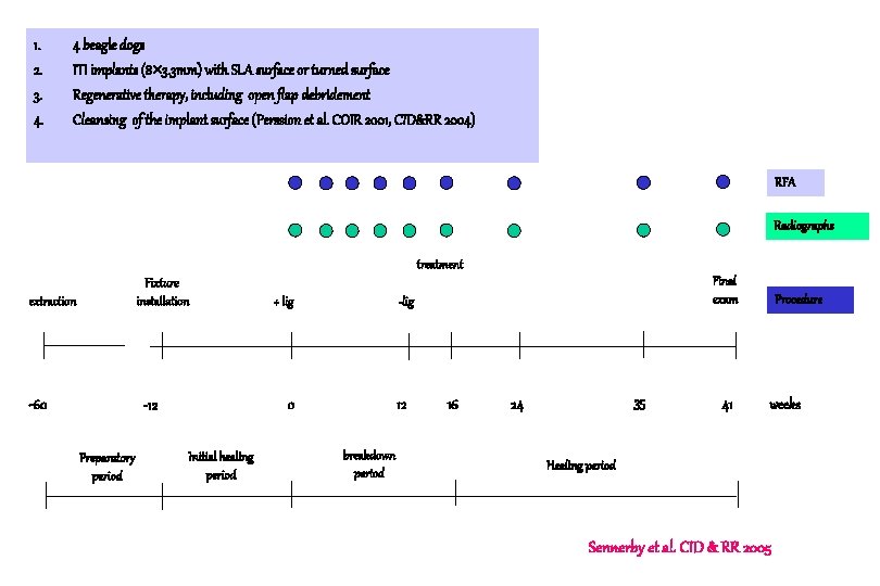
1. 2. 3. 4. 4 beagle dogs ITI implants (8 3. 3 mm) with SLA surface or turned surface Regenerative therapy, including open flap debridement Cleansing of the implant surface (Perssion et al. COIR 2001, CID&RR 2004) RFA Radiographs treatment Fixture installation extraction -60 -lig 0 -12 Preparatory period + lig Initial healing period Final exam 12 breakdown period 16 35 24 41 Procedure weeks Healing period Sennerby et al. CID & RR 2005
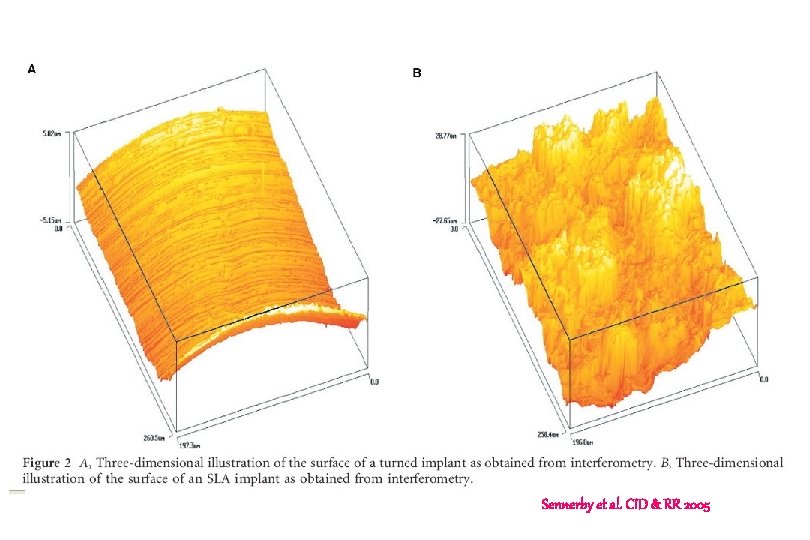
Sennerby et al. CID & RR 2005
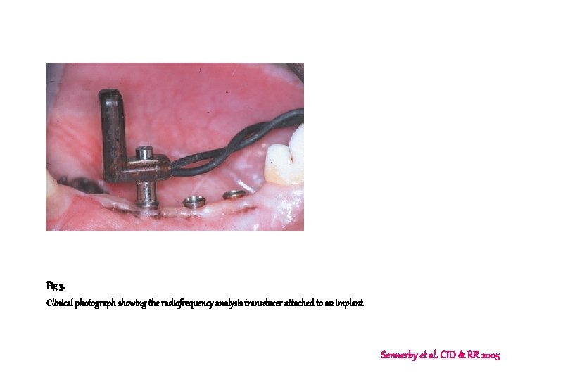
Fig 3. Clinical photograph showing the radiofrequency analysis transducer attached to an implant Sennerby et al. CID & RR 2005
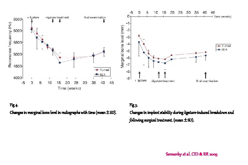
Fig 4. Fig 5. Changes in marginal bone level in radiographs with time (mean SD). Changes in implant stability during ligature-induced breakdown and following surgical treatment. (mean SD). Sennerby et al. CID & RR 2005
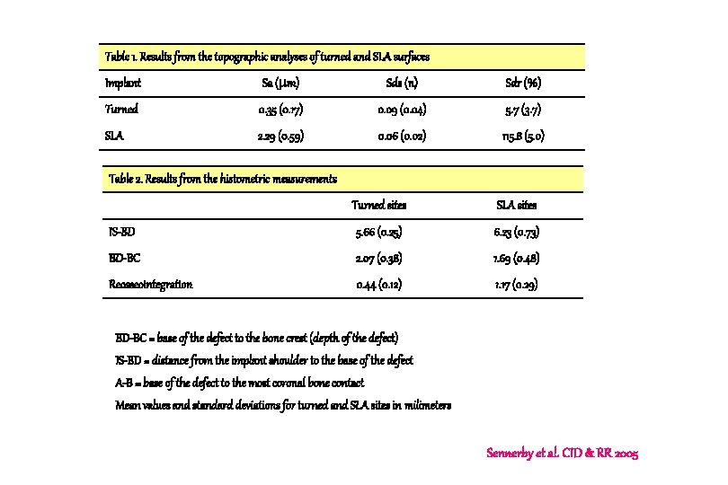
Table 1. Results from the topographic analyses of turned and SLA surfaces Implant Sa ( m) Sds (n) Sdr (%) Turned 0. 35 (0. 17) 0. 09 (0. 04) 5. 7 (3. 7) SLA 2. 29 (0. 59) 0. 06 (0. 02) 115. 8 (5. 0) Table 2. Results from the histometric measurements Turned sites SLA sites IS-BD 5. 66 (0. 25) 6. 23 (0. 73) BD-BC 2. 07 (0. 38) 1. 69 (0. 48) Reosseointegration 0. 44 (0. 12) 1. 17 (0. 29) BD-BC = base of the defect to the bone crest (depth of the defect) IS-BD = distance from the implant shoulder to the base of the defect A-B = base of the defect to the most coronal bone contact Mean values and standard deviations for turned and SLA sites in milimeters Sennerby et al. CID & RR 2005
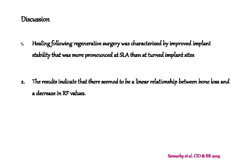
Discussion 1. Healing following regenerative surgery was characterized by improved implant stability that was more pronounced at SLA than at turned implant sites 2. The results indicate that there seemed to be a linear relationship between bone loss and a decrease in RF values. Sennerby et al. CID & RR 2005
Determining factor of RFA 1. One factor is related to the stiffness of the bone-implant system (interfacial stiffness) and 2. The second to the distance between the transducer and the most marginal level of bone -implant contact (the effective implant length) Sennerby et al. CID & RR 2005
Discussion 3. Based on measurements performed on all implant sites included in the current experiment, it could be estimated that 1 mm of bone loss corresponded to a decrease in the RF value that amounted to 413 Hz. 4. During healing following treatment, the RFA measurements indicated a more marked improvement in the stability of the SLA than of the turned implants (483 vs 238 Hz) Sennerby et al. CID & RR 2005
Discussion 5. Both at SLA and turned implant sites, most of the bone defects were resolved during healing by the formation of new bone. 6. At the turned implant sites, in contrast to the SLA sites, however, this new bone was consistently separated from the implant surface by a thin capsule of connective tissue. Sennerby et al. CID & RR 2005