Chapter 4 MultipleIssue Processors 1 Multipleissue processors n


![Simulations [Grunwald] SAg, gshare and MCFarling‘s combining predictor 65 Simulations [Grunwald] SAg, gshare and MCFarling‘s combining predictor 65](https://slidetodoc.com/presentation_image/0fdc2501b2cbe1bd229baedec46f117e/image-65.jpg)


- Slides: 180

Chapter 4 Multiple-Issue Processors 1

Multiple-issue processors n This chapter concerns multiple-issue processors, i. e. superscalar and VLIW (very long instruction word) processors. n Most of today's general-purpose microprocessors are four- or six -issue superscalar often with an enhanced Tomasulo scheme. n VLIW is the choice for most signal processors. n VLIW is proposed as EPIC (explicitly parallel instruction computing) by Intel for its IA-64 ISA. 2

Components of a superscalar processor 3

Floorplan of the Power. PC 604 4

Superscalar pipeline (Power. PC- and enhanced Tomasuloscheme) Instructions in the instruction window are free from control dependencies due to branch prediction, and free from name dependences due to register renaming. n So, only (true) data dependences and structural conflicts remain to be solved. n 5

Superscalar pipeline without reservation stations 6

Superscalar pipeline with decoupled instruction windows 7

Issue The issue logic examines the waiting instructions in the instruction window and simultaneously assigns (issues) a number of instructions to the FUs up to a maximum issue bandwidth. n Several instructions can be issued simultaneously (the issue bandwidth). n The program order of the issued instructions is stored in the reorder buffer. n Instruction issue from the instruction window can be: – in-order (only in program order) or out-of-order – it can be subject to simultaneous data dependences and resource constraints, – or it can be divided in two (or more) stages • checking structural conflict in the first and data dependences in the next stage (or vice versa). • In the case of structural conflicts first, the instructions are issued to reservation stations (buffers) in front of the FUs 8 where the issued instructions await missing operands n

Reservation station(s) n Two definitions in literature: – A reservation station is a buffer for a single instruction with its operands (original Tomasulo paper, Flynn's book, Hennessy/Patterson book). – A reservation station is a buffer (in front of one or more FUs) with one or more entries and each entry can buffer an instruction with its operands (e. g. Power. PC literature). n Depending on the specific processor, reservation stations can be central to a number of FUs or each FU has one or more own reservation stations. n Instructions await their operands in the reservation stations, as in the Tomasulo algorithm. 9

Dispatch (Power. PC- and enhanced Tomasulo -Scheme) n n n An instruction is then said to be dispatched from a reservation station to the FU when all operands are available, and execution starts. If all its operands are available during issue and the FU is not busy, an instruction is immediately dispatched, starting execution in the next cycle after the issue. So, the dispatch is usually not a pipeline stage. An issued instruction may stay in the reservation station for zero to several cycles. Dispatch and execution is performed out of program order. Other authors interchange the meaning of issue and dispatch or use different semantic. 10

Completion n n When the FU finishes the execution of an instruction and the result is ready forwarding and buffering, the instruction is said to complete. Instruction completion is out of program order. During completion the reservation station is freed and the state of the execution is noted in the reorder buffer. The state of the reorder buffer entry can denote an interrupt occurrence. The instruction can be completed and still be speculatively assigned, which is also monitored in the reorder buffer. 11

Commitment After completion, operations are committed in-order. n An instruction can be committed: – if all previous instructions due to the program order are already committed or can be committed in the same cycle, – if no interrupt occurred before and during instruction execution, and – if the instruction is no more on a speculative path. n By or after commitment, the result of an instruction is made permanent in the architectural register set, – usually by writing the result back from the rename register to the architectural register. n 12

Precise interrupt (Precise exception) n If an interrupt occurred, all instructions that are in program order before the interrupt signaling instruction are committed, and all later instructions are removed. n Precise exception means that all instructions before the faulting instruction are committed and those after it can be restarted from scratch. n Depending on the architecture and the type of exception, the faulting instruction should be committed or removed without any lasting effect. 13

Retirement n An instruction retires when the reorder buffer slot of an instruction is freed either – because the instruction commits (the result is made permanent) or – because the instruction is removed (without making permanent changes). n A result is made permanents by copying the result value from the rename register to the architectural register. – This is often done in an own stage after the commitment of the instruction with the effect that the rename register is freed one cycle after commitment. 14

Explanation of the term “superscalar” n Definition: Superscalar machines are distinguished by their ability to (dynamically) issue multiple instructions each clock cycle from a conventional linear instruction stream. n In contrast to superscalar processors, VLIW processors use a long instruction word that contains a usually fixed number of instructions that are fetched, decoded, issued, and executed synchronously. 15

Explanation of the term “superscalar” n Instructions are issued from a sequential stream of normal instructions (in contrast to VLIW where a sequential stream of instruction tuples is used). n The instructions that are issued are scheduled dynamically by the hardware (in contrast to VLIW processors which rely on a static scheduling by the compiler). n More than one instruction can be issued each cycle (motivating the term superscalar instead of scalar). n The number of issued instructions is determined dynamically by hardware, that is, the actual number of instructions issued in a single cycle can be zero up to a maximum instruction issue bandwidth (In contrast to VLIW where the number of scheduled instructions is fixed due to padding instructions with no-ops in case the full issue bandwidth would not be met. ) 16

Explanation of the term “superscalar” n n n Dynamic issue of superscalar processors can allow issue of instructions either in-order, or it can allow also an issue of instructions out of program order. – Only in-order issue is possible with VLIW processors. The dynamic instruction issue complicates the hardware scheduler of a superscalar processor if compared with a VLIW. The scheduler complexity increases when multiple instructions are issued out-of-order from a large instruction window. It is a presumption of superscalar that multiple FUs are available. – The number of available FUs is at least the maximum issue bandwidth, but often higher to diminish potential resource conflicts. The superscalar technique is a microarchitecture technique, not an architecture technique. 17

Please recall: architecture, ISA, microarchitecture n The architecture of a processor is defined as the instruction set architecture (ISA), i. e. everything that is seen outside of a processor. n In contrast, the microarchitecture comprises implementation techniques – like number and type of pipeline stages, issue bandwidth, number of FUs, size and organization of on-chip cache memories etc. – The maximum issue bandwidth and the internal structure of the processor can be changed. – Even several architectural compatible processors may exist with different microarchitectures and all are able to execute the same code. n An optimizing compiler may also use the knowledge of the 18

Sections of a superscalar processor n The ability to issue and execute instructions out-of-order partitions a superscalar pipeline in three distinct sections: – in-order section with the instruction fetch, decode and rename stages - the issue is also part of the in-order section in case of an in-order issue, – out-of-order section starting with the issue in case of an outof-order issue processor, the execution stage, and usually the completion stage, and again an – in-order section that comprises the retirement and write-back stages. 19

Temporal vs. spacial parallelism n Instruction pipelining, superscalar and VLIW techniques all exploit fine-grain (instruction-level) parallelism. n Pipelining utilizes temporal parallelism. n Superscalar and VLIW techniques utilize also spatial parallelism. n Performance can be increased by longer pipelines (deeper pipelining) and faster transistors (a faster clock) emphasizing an improved pipelining. n Provided that enough fine-grain parallelism is available, performance can also be increased by more FUs and a higher issue bandwidth using more transistors in the superscalar and VLIW cases. 20

I-cache access and instruction fetch Harvard architecture: separate instruction and data memory and access paths – is internally used in a high-performance microprocessor with separate on-chip primary I-cache and D-cache. n The I-cache is less complicated to control than the D-cache, because – it is read-only and – it is not subjected to cache coherence in contrast to the Dcache. n n Sometimes the instructions in the I-cache are predecoded on their way from the memory interface to the I-cache to simplify the decode stage. 21

Instruction fetch The main problem of instruction fetching is control transfer performed by jump, branch, call, return, and interrupt instructions: – If the starting PC address is not the address of the cache line, then fewer instructions than the fetch width are returned. – Instructions after a control transfer instruction are invalidated. – A multiple cache lines fetch from different locations may be needed in future very wide-issue processors where often more than one branch will be contained in a single contiguous fetch block. n Problem with target instruction addresses that are not aligned to the cache line addresses: – Self-aligned instruction cache reads and concatenates two consecutive lines within one cycle to be able to always return the full fetch bandwidth. Implementation: • either by use of a dual-port I-cache, • by performing two separate cache accesses in a single 22 cycle, • or by a two-banked I-cache (preferred). n

Prefetching and instruction fetch prediction n Prefetching improves the instruction fetch performance, but fetching is still limited because instructions after a control transfer must be invalidated. n Instruction fetch prediction helps to determine the next instructions to be fetched from the memory subsystem. n Instruction fetch prediction is applied in conjunction with branch prediction. 23

Branch prediction foretells the outcome of conditional branch instructions. n Excellent branch handling techniques are essential for today's and for future microprocessors. n The task of high performance branch handling consists of the following requirements: – an early determination of the branch outcome (the so-called branch resolution), – buffering of the branch target address in a BTAC after its first calculation and an immediate reload of the PC after a BTAC match, – an excellent branch predictor (i. e. branch prediction technique) and speculative execution mechanism, – often another branch is predicted while a previous branch is still unresolved, so the processor must be able to pursue two or more speculation levels, – and an efficient rerolling mechanism when a branch is mispredicted (minimizing the branch misprediction penalty). n 24

Misprediction penalty The performance of branch prediction depends on the prediction accuracy and the cost of misprediction. n Prediction accuracy can be improved by inventing better branch predictors. n Misprediction penalty depends on many organizational features: – the pipeline length (favoring shorter pipelines over longer pipelines), – the overall organization of the pipeline, – the fact if misspeculated instructions can be removed from internal buffers, or have to be executed and can only be removed in the retire stage, – the number of speculative instructions in the instruction window or the reorder buffer. Typically only a limited number of instructions can be removed each cycle. n n Rerolling when a branch is mispredicted is expensive: – 4 to 9 cycles in the Alpha 21264, – 11 or more cycles in the Pentium II. 25

Branch-Target Buffer or Branch-Target Address Cache n n n The Branch Target Buffer (BTB) or Branch-Target Address Cache (BTAC) stores branch and jump target addresses. It should be known already in the IF stage whether the as-yetundecoded instruction is a jump or branch. The BTB is accessed during the IF stage. The BTB consists of a table with branch addresses, the corresponding target addresses, and prediction information. Variations: Branch Target Cache (BTC): stores one or more target instructions additionally. Return Address Stack (RAS): a small stack of return addresses for procedure calls and returns is used additional to and independent of a BTB. 26

Branch-Target Buffer or Branch-Target Address Cache Branch address . . . Prediction Target address bits . . . 27

Static branch prediction n Static Branch Prediction predicts always the same direction for the same branch during the whole program execution. n It comprises hardware-fixed prediction and compiler-directed prediction. n Simple hardware-fixed direction mechanisms can be: – Predict always not taken – Predict always taken – Backward branch predict taken, forward branch predict not taken n Sometimes a bit in the branch opcode allows the compiler to decide the prediction direction. 28

Dynamic branch prediction n In a dynamic branch prediction scheme the hardware influences the prediction while execution proceeds. n Prediction is decided on the computation history of the program. n After a start-up phase of the program execution, where a static branch prediction might be effective, the history information is gathered and dynamic branch prediction gets effective. n In general, dynamic branch prediction gives better results than static branch prediction, but at the cost of increased hardware complexity. 29

One-bit predictor T NT Predict Taken Predict Not Taken T NT 30

One-bit vs. two-bit predictors A one-bit predictor correctly predicts a branch at the end of a loop iteration, as long as the loop does not exit. n In nested loops, a one-bit prediction scheme will cause two mispredictions for the inner loop: – One at the end of the loop, when the iteration exits the loop instead of looping again, and – one when executing the first loop iteration, when it predicts exit instead of looping. n Such a double misprediction in nested loops is avoided by a twobit predictor scheme. n Two-bit Prediction: A prediction must miss twice before it is changed when a two-bit prediction scheme is applied. n 31

Two-bit predictors (Saturation Counter Scheme) T (11) Predict Strongly Taken NT T (10) Predict Weakly Taken NT T (01) Predict Weakly Not Taken NT T (00) Predict Strongly Not Taken NT 32

Two-bit predictors (Hysteresis Scheme) NT T (11) Predict Strongly Taken NT T (10) Predict Weakly Taken (01) Predict Weakly Not Taken NT T (00) Predict Strongly Not Taken NT T 33

Two-bit predictors n n n The two-bit prediction scheme is extendable to an n-bit scheme. Studies showed that a two-bit prediction scheme does almost as well as an n-bit scheme with n>2. Two-bit predictors can be implemented in the Branch Target Buffer (BTB) assigning two state bits to each entry in the BTB. Another solution is to use a BTB for target addresses and a separate Branch History Table (BHT) as prediction buffer. A mispredict in the BHT occurs due to two reasons: – either a wrong guess for that branch, – or the branch history of a wrong branch is used because the table is indexed. In an indexed table lookup part of the instruction address is used as index to identify a table entry. 34

Two-bit predictors and correlation-based prediction n Two-bit predictors work well for programs which contain many frequently executed loop-control branches (floating-point intensive programs). n Shortcomings arise from dependent (correlated) branches, which are frequent in integer-dominated programs. 35

Example: if (d==0) d=1; if (d==1). . . /* branch b 1*/ /*branch b 2 */ bnez R 1, L 1 ; branch b 1 (d 0) addi R 1, R 0, #1 ; d==0, so d=1 L 1: subi R 3, R 1, #1 bnez R 3, L 2 ; branch b 2 (d 0) . . . L 2: . . . n Consider a sequence where d alternates between 0 and 2 ? ? a sequence of NT-T-NT-T for branches b 1 and b 2 n The execution behavior is given in the following table: 36

One-bit predictor initialized to “predict taken” bnez R 1, L 1 ; branch b 1 (d 0) addi R 1, R 0, #1 L 1: ; d==0, so d=1 subi R 3, R 1, #1 ; branch b 2 (d 0) bnez R 3, L 2. . . L 2: b 1: b 2: . . . d alternates between 0 and 2 Initial prediction d==0 d==2 d==0 T T NT NT 37

Two-bit saturation counter predictor initialized to “predict weakly taken” T (11) Predict Strongly Taken NT T NT (10) Predict Weakly Taken (01) Predict Weakly Not Taken T bnez R 1, L 1 T (00) Predict Strongly Not Taken NT ; branch b 1 (d 0) addi R 1, R 0, #1 L 1: NT ; d==0, so d=1 subi R 3, R 1, #1 bnez R 3, L 2 ; branch b 2 (d 0) . . . L 2: b 1: b 2: . . . d alternates between 0 and 2 Initial prediction d==0 d==2 d==0 WT WT WNT WNT 38

Two-bit predictor (Hysteresis counter) initialized to “predict weakly taken” NT T (11) Predict Strongly Taken NT T (10) Predict Weakly Taken (01) Predict Weakly Not Taken NT T (00) Predict Strongly Not Taken NT T bnez R 1, L 1 ; branch b 1 (d 0) addi R 1, R 0, #1 L 1: subi R 3, R 1, #1 ; branch b 2 (d 0) bnez R 3, L 2. . . L 2: b 1: b 2: ; d==0, so d=1 . . . d alternates between 0 and 2 Initial prediction d==0 d==2 d==0 WT WT SNT WNT SNT 39

Predictor behavior in example n A one-bit predictor initialized to “ predict taken” for branches b 1 and b 2, every branch is mispredicted. n A two-bit predictor of of saturation counter scheme starting from the state “predict weakly taken” every branch is mispredicted. n The two-bit predictor of Ultra. SPARC mispredicts every second branch execution of b 1 and b 2. n A (1, 1) correlating predictor takes advantage of the correlation of the two branches; it mispredicts only in the first iteration when d = 2. 40

Correlation-based predictor n n n The two-bit predictor scheme uses only the recent behavior of a single branch to predict the future of that branch. Correlations between different branch instructions are not taken into account. The correlation-based predictors or correlating predictors are branch predictors that additionally use the behavior of other branches to make a prediction. While two-bit predictors use self-history only, the correlating predictor uses neighbor history additionally. Notation: (m, n)-correlation-based predictor or (m, n)-predictor uses the behavior of the last m branches to choose from 2 m branch predictors, each of which is a n-bit predictor for a single branch. Branch history register (BHR): The global history of the most recent m branches can be recorded in a m-bit shift register where 41 each bit records whether the branch was taken or not taken.

Correlation-based prediction (2, 2)predictor Pattern History Tables PHTs (2 -bit predictors) Branch address . . . . 10 1. . . select Branch History Register BHR (2 -bit shift register) 1 0 42

Prediction behavior of (1, 1) correlating predictor bnez R 1, L 1 ; branch b 1 (d 0) addi R 1, R 0, #1 L 1: ; d==0, so d=1 subi R 3, R 1, #1 bnez R 3, L 2 ; branch b 2 (d 0) . . . L 2: d alternates between 0 and 2 . . . b 1 b 2 BHR Initial prediction b 1: b 2: 0: 1 1 1 PHT d==0 T T 43

Prediction behavior of (1, 1) correlating predictor bnez R 1, L 1 ; branch b 1 (d 0) addi R 1, R 0, #1 L 1: ; d==0, so d=1 subi R 3, R 1, #1 bnez R 3, L 2 ; branch b 2 (d 0) . . . L 2: d alternates between 0 and 2 . . . b 1 b 2 BHR Initial prediction b 1: b 2: T T 0: 1 1 1: 0 1 0 PHT d==0 NT 44

Prediction behavior of (1, 1) correlating predictor bnez R 1, L 1 ; branch b 1 (d 0) addi R 1, R 0, #1 L 1: ; d==0, so d=1 subi R 3, R 1, #1 bnez R 3, L 2 ; branch b 2 (d 0) . . . L 2: d alternates between 0 and 2 . . . b 1 b 2 BHR b 1: b 2: 0: 1 0 1: 0 1 0 Initial prediction d==0 T T NT NT PHT d==2 45

Prediction behavior of (1, 1) correlating predictor bnez R 1, L 1 ; branch b 1 (d 0) addi R 1, R 0, #1 L 1: ; d==0, so d=1 subi R 3, R 1, #1 bnez R 3, L 2 ; branch b 2 (d 0) . . . L 2: d alternates between 0 and 2 . . . b 1 b 2 BHR b 1: b 2: 0: 1 0 1: 0 1 1 Initial prediction d==0 d==2 T T NT NT T PHT 46

Prediction behavior of (1, 1) correlating predictor bnez R 1, L 1 ; branch b 1 (d 0) addi R 1, R 0, #1 L 1: ; d==0, so d=1 subi R 3, R 1, #1 bnez R 3, L 2 ; branch b 2 (d 0) . . . L 2: d alternates between 0 and 2 . . . b 1 b 2 BHR b 1: b 2: 0: 1 0 1: 0 1 1 Initial prediction d==0 d==2 T T NT NT T T PHT 47

Two-level adaptive predictors n n n Developed by Yeh and Patt at the same time (1992) as the correlation-based prediction scheme. The basic two-level predictor uses a single global branch history register (BHR) of k bits to index in a pattern history table (PHT) of 2 -bit counters. Global history schemes correspond to correlation-based predictor schemes. Denotation: GAg: – a single global BHR (denoted G) and – a single global PHT (denoted g), – A stands for adaptive. All PHT implementations of Yeh and Patt use 2 -bit predictors. GAg-predictor with a 4 -bit BHR length is denoted as GAg(4). 48

Implementation of a GAg(4)-predictor Branch History Register (BHR) shift direction 1 1 0 0 Index Branch Pattern History Table (PHT) . . . 1100 1 1 predict: taken . . . n In the GAg predictor schemes the PHT lookup depends entirely on the bit pattern in the BHR and is completely independent of the branch address. 49

Mispredictions can be restrained by additionally using: n n n the full branch address to distinguish multiple PHTs (called per-address PHTs), a subset of branches (e. g. n bits of the branch address) to distinguish multiple PHTs (called per-set PHTs), the full branch address to distinguish multiple BHRs (called per-address BHRs), a subset of branches to distinguish multiple BHRs (called per-set BHRs), or a combination scheme. 50

Implementation of a GAp(4) predictor Branch address Per-address PHTs BHR . . . 1 1 0 0 Index . . . 1. . . Gap(4) means a 4 -bit BHR n a PHT for each branch. n 51

GAs(4, 2 n) n bits of branch address Per-set PHTs n BHR . . . 1 1 0 0 Index . . . 1. . . Gas(4, 2 n) means a 4 -bit BHR n n bits of the branch address are used to choose among 2 n PHTs with 24 entries each. n 52

Compare correlation-based (2, 2)-predictor (left) with two-level adaptive GAs(4, 2 n) predictor n bits of branch address (right) Per-set PHTs n BHR . . . 1 1 0 0 Index Pattern History Tables PHTs (2 -bit predictors) Branch address . . . . 10 1. . . select Branch History Register BHR (2 -bit shift register) 1 0 53

Two-level adaptive predictors: Per-address history schemes The first-level branch history refers to the last k occurrences of the same branch instruction (using self-history only!) n Therefore a BHR is associated with each branch instruction. n The per-address branch history registers are combined in a table that is called per-address branch history table (PBHT). n In the simplest per address history scheme, the BHRs index into a single global PHT. denoted as PAg (multiple per-address indexed BHRs, and a single global PHT). n 54

PAg(4) Per-address BHT Branch address 1 . . . 1 0 Branch address 1 1 0. . . PHT. . . 0 0 1 1 Index. . . 55

PAp(4) b 1 b 2 Per-address BHT Branch address b 1 Branch address b 2 1 . . . 1 0 0 1 1 0 0 . . . Per-address PHTs . . . 1 Index. . . 1 . . . 0 1. . . 56

Two-level adaptive predictors: Per-set history schemes n Per-set history schemes (SAg, SAs, and SAp): the firstlevel branch history means the last k occurrences of the branch instructions from the same subset. Each BHR is associated with a set of branches. n Possible Set attributes: – branch opcode, – the branch class assigned by the compiler, or – the branch address (most important!). 57

SAg(4) Per-set BHT n bits of branch address n n n bits of branch address PHT 1 . . . 1 0 0 1 1 0 0 . . . 1 1 Index. . . 58

SAs(4) b 1, b 2 Per-set BHT n bits of branch address b 1 n bits of branch address b 2 . . . n n 1 1 0. . . Per-set PHTs n . . . 0 1 . . 1 Index. . 59

Two-level adaptive predictors Full table: single global PHT address PHTs single global BHR per-address BHT per-set BHT SAp GAg PAg per-set PHTs GAs PAs SAg per. GAp PAp SAs 60

Estimation of hardware costs In the table b is the number of PHTs or entries in the BHT for the per-address schemes. P and s denotes the number of PHTs or entries in the BHT for the per-set schemes. 61

Two-level adaptive predictors Simulations of Yeh and Patt using the SPEC 89 benchmarks n n n The performance of the global history schemes is sensitive to the branch history length. Interference of different branches that are mapped to the same pattern history table is decreased by lengthening the global BHR. Similarly adding PHTs reduces the possibility of pattern history interference by mapping interfering branches into different tables. Global history schemes are better than the per-address schemes for the integer SPEC 89 programs, – utilize branch correlation, which is often the case in the frequent if-then-else statements in integer programs Per-address schemes are better for the floating-point intensive programs. – better in predicting loop-control branches which are frequent in the floating-point SPEC 89 benchmark programs. The per-set history schemes are in between both other schemes. 62

gselect and gshare predictors gselect predictor: concatenates some lower order bit of the branch address and the global history n gshare predictor: uses the bitwise exclusive OR of part of the branch address and the global history as hash function. n Mc. Farling: gshare slightly better than gselect n Branch Address BHR 00000001 00000000 1111 10000000 gselect 4/4 gshare 8/8 00000001 00000000 11110000 11110000 01111111 63

Hybrid predictors n The second strategy of Mc. Farling is to combine multiple separate branch predictors, each tuned to a different class of branches. n Two or more predictors and a predictor selection mechanism are necessary in a combining or hybrid predictor. – Mc. Farling: combination of two-bit predictor and gshare twolevel adaptive, – Young and Smith: a compiler-based static branch prediction with a two-level adaptive type, – and many more combinations! n Hybrid predictors often better than single-type predictors. 64
![Simulations Grunwald SAg gshare and MCFarlings combining predictor 65 Simulations [Grunwald] SAg, gshare and MCFarling‘s combining predictor 65](https://slidetodoc.com/presentation_image/0fdc2501b2cbe1bd229baedec46f117e/image-65.jpg)
Simulations [Grunwald] SAg, gshare and MCFarling‘s combining predictor 65

Results Simulation of Keeton et al. 1998 using an OLTP (online transaction workload) on a Pentium. Pro multiprocessor reported a misprediction rate of 14% with an branch instruction frequency of about 21%. n The speculative execution factor, given by the number of instructions decoded divided by the number of instructions committed, is 1. 4 for the database programs. n Two different conclusions may be drawn from these simulation results: – Branch predictors should be further improved – and/or branch prediction is only effective if the branch is predictable. n If a branch outcome is dependent on irregular data inputs, the branch often shows an irregular behavior. n Question: Confidence of a branch prediction? 66

Predicated instructions and multipath execution - Confidence estimation n Confidence estimation is a technique for assessing the quality of a particular prediction. n Applied to branch prediction, a confidence estimator attempts to assess the prediction made by a branch predictor. n A low confidence branch is a branch which frequently changes its branch direction in an irregular way making its outcome hard to predict or even unpredictable. n Four classes possible: – correctly predicted with high confidence C(HC), – correctly predicted with low confidence C(LC), – incorrectly predicted with high confidence I(HC), and – incorrectly predicted with low confidence I(LC). 67

Implementation of a confidence estimator n Information from the branch prediction tables is used: – Use of saturation counter information to construct a confidence estimator speculate more aggressively when the confidence level is higher – Used of a miss distance counter table (MDC): Each time a branch is predicted, the value in the MDC is compared to a threshold. If the value is above threshold, then the branch is considered to have high confidence, and low confidence otherwise. – A small number of branch history patterns typically leads to correct predictions in a PAs predictor scheme. The confidence estimator assigned high confidence to a fixed set of patterns and low confidence to all others. n Confidence estimation can be used for speculation control, thread switching in multithreaded processors or multipath 68

Predicated instructions n n n Provide predicated or conditional instructions and one or more predicate registers. Predicated instructions use a predicate register as additional input operand. The Boolean result of a condition testing is recorded in a (onebit) predicate register. Predicated instructions are fetched, decoded and placed in the instruction window like non predicated instructions. It is dependent on the processor architecture, how far a predicated instruction proceeds speculatively in the pipeline before its predication is resolved: – A predicated instruction executes only if its predicate is true, otherwise the instruction is discarded. In this case predicated instructions are not executed before the predicate is resolved. – Alternatively, as reported for Intel's IA 64 ISA, the predicated 69 instruction may be executed, but commits only if the

Predication example if (x = = 0) { a = b + c; d = e - f; } g = h * i; /*branch b 1 */ /* instruction independent of branch b 1 */ (Pred = (x = = 0) ) /* branch b 1: Pred is set to true in x equals 0 */ if Pred then a = b + c; /* The operations are only performed */ if Pred then e = e - f; /* if Pred is set to true */ g = h * i; 70

Predication Able to eliminate a branch and therefore the associated branch prediction increasing the distance between mispredictions. n The the run length of a code block is increased better compiler scheduling. n Predication affects the instruction set, adds a port to the register file, and complicates instruction execution. n Predicated instructions that are discarded still consume processor resources; especially the fetch bandwidth. n Predication is most effective when control dependences can be completely eliminated, such as in an if-then with a small then body. n The use of predicated instructions is limited when the control flow involves more than a simple alternative sequence. n 71

Eager (multipath) execution Execution proceeds down both paths of a branch, and no prediction is made. n When a branch resolves, all operations on the non-taken path are discarded. n n Oracle execution: eager execution with unlimited resources – gives the same theoretical maximum performance as a perfect branch prediction n With limited resources, the eager execution strategy must be employed carefully. n Mechanism is required that decides when to employ prediction and when eager execution: e. g. a confidence estimator n Rarely implemented (IBM mainframes) but some research projects: – Dansoft processor, Polypath architecture, selective dual path execution, simultaneous speculation scheduling, disjoint 72

(a) Single path speculative execution. 3. 7 (b) Full eager 1 execution. 21. 49 (c) Disjoint eager 2. 15. 34 execution 3. 24 . 7 . 10 . 49 2 . 07 . 12 6 (a) . 3 2 1 5. 05 . 49 3 (b) . 21 4 4 1 4. 17 . 3 . 09 . 21 5 . 34 3 6. 24 5 (c) . 21 6 . 15 . 10 73

Prediction of indirect branches n Indirect branches, which transfer control to an address stored in register, are harder to predict accurately. n Indirect branches occur frequently in machine code compiled from object-oriented programs like C++ and Java programs. n One simple solution is to update the PHT to include the branch target addresses. 74

Branch handling techniques and implementations Technique Implementation examples No branch prediction Intel 8086 Static prediction always not taken Intel i 486 always taken Super. SPARC backward taken, forward not taken HP PA-7 x 00 semistatic with profiling early Power. PCs Dynamic prediction: 1 -bit DEC Alpha 21064, AMD K 5 2 -bit Power. PC 604, MIPS R 10000, Cyrix 6 x 86 and M 2, Nex. Gen 586 two-level adaptive Intel Pentium. Pro, Pentium II, AMD K 6 Hybrid prediction DEC Alpha 21264 Predication Intel/HP Merced and most signal processors as e. g. ARM processors, TI TMS 320 C 6201 and many other Eager execution (limited) IBM mainframes: IBM 360/91, IBM 3090 Disjoint eager execution none yet 75

High-bandwidth branch prediction n Future microprocessor will require more than one prediction per cycle starting speculation over multiple branches in a single cycle, – e. g. Gag predictor is independent of branch address. n When multiple branches are predicted per cycle, then instructions must be fetched from multiple target addresses per cycle, complicating I-cache access. – Possible solution: Trace cache in combination with next trace prediction. n Most likely a combination of branch handling techniques will be applied, – e. g. a multi-hybrid branch predictor combined with support for context switching, indirect jumps, and interference handling. 76

Details of superscalar pipeline In-order section: – Instruction Fetch (BTAC access, simple branch prediction) Fetch buffer – Instruction decode • often: more complex branch prediction techniques • Register Rename Instruction window n Out-of-order section: – Instruction issue to FU or Reservation station – Execute till completion n In-order section: – Retire (commit or remove) – Write-back n 77

Decode stage n n n Superscalar processor: In-order delivery of instructions to the out-of-order execution kernel! Instruction Delivery: – Fetch and decode instructions at a higher bandwidth than execute them. – Delivery task: Keep instruction window kept full the deeper instruction look-ahead allows to find more instructions to issue to the execution units. The processor fetches and decodes today about 1. 4 to twice as many instructions than it commits (because of mispredicted branch paths). Typically the decode bandwidth is the same as the instruction fetch bandwidth. Multiple instruction fetch and decode is supported by a fixed instruction length. 78

Decoding variable-length instructions n Variable instruction length: often the case for legacy CISC instruction sets as the Intel i 86 ISA. a multistage decode is necessary. – The first stage determines the instruction limits within the instruction stream. – The second stage decodes the instructions generating one or several micro-ops from each instruction. n Complex CISC instructions are split into micro-ops which resemble ordinary RISC instructions. 79

Predecoding n Predecoding can be done when the instructions are transferred from memory or secondary cache to the I-cache. the decode stage is more simple. MIPS R 10000: predecodes each 32 -bit instruction into a 36 -bit format stored in the I-cache. – The four extra bits indicate which functional unit should execute the instruction. – The predecoding also rearranges operand- and destinationselect fields to be in the same position for every instruction, and – modifies opcodes to simplify decoding of integer or floatingpoint destination registers. n The decoder can decode this expanded format more rapidly than the original instruction format. n 80

Rename stage Aim of register renaming: remove anti and output dependencies dynamically by the processor hardware. n Register renaming is the process of dynamically associating physical registers (rename registers) with the architectural registers (logical registers) referred to in the instruction set of the architecture. n Implementation: – mapping table; – a new physical register is allocated for every destination register specified in an instruction. n Each physical register is written only once after each assignment from the free list of available registers. n If a subsequent instruction needs its value, that instruction must wait until it is written (true data dependence). n 81

Two principal techniques to implement renaming Separate sets of architectural registers and rename (physical) registers are provided. – The physical registers contain values (of completed but not yet retired instructions), – the architectural (or logical) registers store the committed values. – After commitment of an instruction, copying its result from the rename register to the architectural register is required. n Only a single set of registers is provided and architectural registers are dynamically mapped to physical registers. – The physical registers contain committed values and temporary results. – After commitment of an instruction, the physical register is made permanent and no copying is necessary. n n Alternative to the dynamic renaming is the use of a large register file as defined for the Intel IA-64 (Itanium). 82

Register rename logic Access a multi-ported map table with logical register designators as index n Additionally dependence check logic detects cases where the logical register is written by an earlier instruction set up output MUXes n 83

Issue and dispatch n n n The notion of the instruction window comprises all the waiting stations between decode (rename) and execute stages. The instruction window isolates the decode/rename from the execution stages of the pipeline. Instruction issue is the process of initiating instruction execution in the processor's functional units. – issue to a FU or a reservation station – dispatch, if a second issue stage exists to denote when an instruction is started to execute in the functional unit. The instruction-issue policy is the protocol used to issue instructions. The processor's lookahead capability is the ability to examine instructions beyond the current point of execution in hope of finding independent instructions to execute. 84

Instruction window organizations Single-stage issue out of a central instruction window n Multi-stage issue: Operand availability and resource availability checking is split into two separate stages. n Decoupling of instruction windows: Each instruction window is shared by a group of (usually related) functional units, most common: separate floating-point window and integer window. n Combination of multi-stage issue and decoupling of instruction windows: – In a two-stage issue scheme with resource dependent issue preceding the data-dependent dispatch, the first stage is done in-order, the second stage is performed out-of-order. n 85

The following issue schemes are commonly used n Single-level, central issue: single-level issue out of a central window as in Pentium II processor Issue and Dispatch Decode and Rename Functional Units 86

Single-level, two-window issue n Single-level, two-window issue: single-level issue with a instruction window decoupling using two separate windows – most common: separate floating point and integer windows as in HP 8000 processor Issue and Dispatch Decode and Rename Functional Units 87

Two-level issue with multiple windows n Two-level issue with multiple windows with a centralized window in the first stage and separate windows in the second stage (Power. PC 604 and 620 processors). Issue Dispatch Functional Unit Decode and Rename Functional Unit Reservation Stations 88

Wakeup logic Result tag broadcast to all instructions in window If match rdy. L or rdy. R flag set If both ready flag set REQ signal raised 89

Selection logic REQ signals are raised when all operands are available 90

Execution stages n Various types of FUs classified as: – single-cycle (latency of one) or – multiple-cycle (latency more than one) units. n Single-cycle units produce a result one cycle after an instruction started execution. Usually they are also able to accept a new instruction each cycle (throughput of one). Multi-cycle units perform more complex operations that cannot be implemented within a single cycle. n Multi-cycle units – can be pipelined to accept a new operation each cycle or each other cycle – or they are non-pipelined. n Another class of units exists that perform the operations with variable cycle times. n 91

Types of FUs n n n Siingle-cycle (single latency) units: – (simple) integer and (integer-based) multimedia units, Multicycle units that are pipelined (throughput of one): – complex integer, floating-point, and (floating-point -based) multimedia unit (also called multimedia vector units), Multicycle units that are pipelined but do not accept a new operation each cycle (throughput of 1/2 or less): – often the 64 -bit floating-point operations in a floating-point unit, Multicycle units that are often not pipelined: – division unit, square root units, complex multimedia units Variable cycle time units: – load/store unit (depending on cache misses) and special implementations of e. g. floating-point units 92

Media processors and multimedia units Media processing (digital multimedia information processing) is the decoding, encoding, interpretation, enhancement, and rendering of digital multimedia information. n Todays video and 3 D graphics require high bandwidth and processing performance: – Separate special-purpose video chips e. g. for MPEG-2, 3 Dgraphics, etc. and multi-algorithm video chip sets – Programmable video processors (very sophisticated DSPs): TMS 320 C 82, Siemens Tricore, Hyperstone – Media processors and media coprocessors: Chromatics MPACT media processor, Philips Trimedia TM-1, Micro. Unity Media processor – Multimedia units: multimedia-extensions for general-purpose processors (VIS, MMX, MAX) n 93

Media processors and multimedia units n Utilization of subword parallelism (data parallel instructions, SIMD) R 1: R 2: x 1 x 2 x 3 x 4 * y 1 * * y 2 y 3 y 4 * R 3: x 1*y 1 x 2*y 2 x 3*y 3 x 4*y 4 Saturation arithmetic n Additional arithmetic instructions, e. g. pavgusb (average instruction), masking and selection instructions, reordering and conversion n 94

Multimedia extensions in today's microprocessors n n n Multimedia acceleration extensions (MAX-1, MAX-2) for HP PA 8000 and PA-8500 Visual instruction set (VIS) for Ultra. SPARC Matrix manipulation extensions (MMX, MMX 2) for the Intel P 55 C and Pentium II Alti. Vec extensions for Motorola processors Motion video instructions (MVI) for Alpha processors and MIPS digital media extensions (MDMX) for MIPS processors. 3 D Graphical Enhancements: n ISSE (internet streaming SIMD extension) extends MMX in Pentium III n 3 DNow! of AMD K 6 -2 and Athlon 95

3 D graphical enhancement n n n The ultimate goal is the integrated real-time processing of multiple audio, video, and 2 -D and 3 -D graphics streams on a system CPU. To speed up 3 D applications by the main processor, fast low precision floating-point operations are required: – reciprocal instructions are of specific importance – e. g. square root reciprocal with low precision. 3 D graphical enhancements apply so-called vector operations: – execute two paired single-precision floating-point operations in parallel on two single-precision floating-point values stored in an 64 bit floating-point register. Such vector operations are defined by 3 Dnow! extension by AMD and by ISSE of Intel's Pentium III. The 3 DNow! defines 21 new instructions which are mainly paired single-precision floating-point operations. 96

Finalizing pipelined execution completion, commitment, retirement and write-back An instruction is completed when the FU finished the execution of the instruction and the result is made available forwarding and buffering. – Instruction completion is out of program order. n Committing an operation means that the results of the operation have been made permanent and the operation retired from the scheduler. n Retiring means removal from the scheduler with or without the commitment of operation results, whichever is appropriate. – Retiring an operation does not imply the results of the operation are either permanent or non permanent. n A result is made permanent: – either by making the mapping of architectural to physical register permanent (if no separate physical registers exist) or – by copying the result value from the rename register to the architectural register ( in case of separate physical and architectural registers) in an own write-back stage after the commitment! n 97

Precise interrupts An interrupt or exception is called precise if the saved processor state corresponds with the sequential model of program execution where one instruction execution ends before the next begins. n The saved state should fulfil the following conditions: – All instructions preceding the instruction indicated by the saved program counter have been executed and have modified the processor state correctly. – All instructions following the instruction indicated by the saved program counter are unexecuted and have not modified the processor state. – If the interrupt is caused by an exception condition raised by an instruction in the program, the saved program counter points to the interrupted instruction. – The interrupted instruction may or may not have been executed, depending on the definition of the architecture and the cause of the interrupt. 98 Whichever is the case, the interrupted instruction has either n

Precise interrupts Interrupts belong to two classes: – Program interrupts or traps result from exception conditions detected during fetching and execution of specific instructions • illegal opcodes, numerical errors such as overflow, or • part of normal execution, e. g. , page faults. – External interrupts are caused by sources outside of the currently executing instruction stream • I/O interrupts and timer interrupts. • For such interrupts restarting from a precise processor state should be made possible. n When an exception condition can be detected prior to issue, then instruction issuing is simply halted and the processor waits until all previous issued instructions are retired. n Processors often have two modes of operation: One mode guarantees precise exception and another mode, which is often 10 times faster, does not. n 99

Reorder buffers n n n The reorder buffer keeps the original program order of the instructions after instruction issue and allows result serialization during the retire stage. State bits store if an instruction is on a speculative path, and when the branch is resolved, if the instruction is on a correct path or must be discarded. When an instruction completes, the state is marked in its entry. Exceptions are marked in the reorder buffer entry of the triggering instruction. The reorder buffer is implemented as a circular FIFO buffer. Reorder buffer entries are allocate in the (first) issue stage and deallocated serially when the instruction retires. 100

Reorder buffer variations n Reorder buffer holds only instruction execution states (results are in rename registers). – Johnson's description of a reorder buffer in combination with a so-called future file. The future file is similar to the set of rename registers that are separate to the architectural registers. – In contrast, Smith and Pleskun describe a reorder buffer in combination with a future file, whereby the reorder buffer and the future file receive and store results at the same time. n Other reorder buffer type: The reorder buffer holds the result values of completed instructions instead of rename registers. n Moreover the instruction window can be combined with the reorder buffer to a single buffer unit. 101

Other recovery mechanisms Checkpoint repair mechanism: – The processor provides a set of logical spaces, where each logical space consists of a full set of software-visible registers and memory. – One is used for current execution, the others contain back-up copies of the in-order state that corresponds to previous points in execution. – At various times during execution, a check-point is made by copying the architectural state of the current logical state to the back-up space. – Restarting is accomplished by loading the contents of the appropriate back-up stage into the current logical state. n History buffer: – The (architectural) register file contains the current state, and the history buffer contains old register values which have been replaced by new values. 102 – The history buffer is managed as LIFO stack, and the old n

Relaxing in-order retirement The only relaxation can be existent in the order of load and store instructions. n Result serialization as it is demanded by the serial instruction flow of the von Neumann architecture. n A fully parallel and highly speculative processor must look like a simple von Neumann processor as it was state-of-the-art in the fifties. n Possible relaxation: – Assume an instruction sequence A ends with a branch that predicts an instruction sequence B, and B is followed by a sequence C which is not dependent on B. – Thus C is executed independently from the branch direction. – Therefore, instructions in C can start to retire before B. n 103

The Intel P 5 and P 6 family P 5 P 6 Net Burst including L 2 cache 104

Micro-dataflow in Pentium. Pro 1995 n . . . The flow of the Intel Architecture instructions is predicted and these instructions are decoded into micro-operations ( ops), or series of ops, and these ops are register-renamed, placed into an out-of-order speculative pool of pending operations, executed in dataflow order (when operands are ready), and retired to permanent machine state in source program order. . n R. P. Colwell, R. L. Steck: A 0. 6 m Bi. CMOS Processor with Dynamic Execution, International Solid State Circuits Conference, Feb. 1995. 105

Pentium. Pro and Pentium II/III n n n The Pentium II/III processors use the same dynamic execution microarchitecture as the other members of P 6 family. This three-way superscalar, pipelined micro-architecture features a decoupled, multi-stage superpipeline, which trades less work per pipestage for more stages. The Pentium II/III processor has twelve stages with a pipestage time 33 percent less than the Pentium processor, which helps achieve a higher clock rate on any given manufacturing process. A wide instruction window using an instruction pool. Optimized scheduling requires the fundamental “execute” phase to be replaced by decoupled “issue/execute” and “retire” phases. This allows instructions to be started in any order but always be retired in the original program order. Processors in the P 6 family may be thought of as three independent engines coupled with an instruction pool. 106

Pentium® Processor and Pentium II/III Microarchitecture 107

Pentium. External Bus II/III L 2 Cache Memory Reorder Buffer Bus Interface Unit Instruction Fetch Unit (with I-cache) Branch Target Buffer Instruction Decode Unit Microcode Instruction Sequencer Register Alias Table Reservation Station Unit D-cache Unit Memory Interface Unit Functional Units Reorder Buffer & Retirement Register File 108

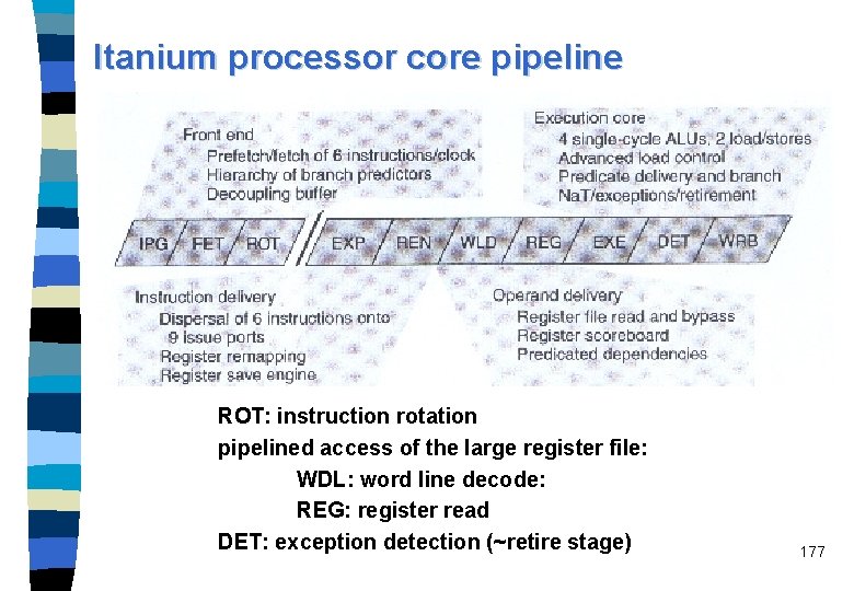
Pentium II/III: The in-order section The instruction fetch unit (IFU) accesses a non-blocking I-cache, it contains the Next IP unit. n The Next IP unit provides the I-cache index (based on inputs from the BTB), trap/interrupt status, and branch-misprediction indications from the integer FUs. n Branch prediction: – two-level adaptive scheme of Yeh and Patt, – BTB contains 512 entries, maintains branch history information and the predicted branch target address. – Branch misprediction penalty: at least 11 cycles, on average 15 cycles n The instruction decoder unit (IDU) is composed of three separate decoders n 109

Pentium II/III: The in-order section (Continued) A decoder breaks the IA-32 instruction down to ops, each comprised of an opcode, two source and one destination operand. These ops are of fixed length. – Most IA-32 instructions are converted directly into single micro ops (by any of the three decoders), – some instructions are decoded into one-to-four ops (by the general decoder), – more complex instructions are used as indices into the microcode instruction sequencer (MIS) which will generate the appropriate stream of ops. n The ops are send to the register alias table (RAT) where register renaming is performed, i. e. , the logical IA-32 based register references are converted into references to physical registers. n Then, with added status information, ops continue to the reorder buffer (ROB, 40 entries) and to the reservation station unit (RSU, 20 entries). n 110

The fetch/decode unit Instruction Fetch Unit Next_IP Simple Decoder Microcode Instruction Sequencer Alignment Simple Decoder Branch Target Buffer Instruction Decode Unit IA-32 instructions General Decoder I-cache (b) instruction decoder unit (IDU) op 1 op 2 op 3 Register Alias Table (a) in-order section 111

The out-of-order execute section n n When the ops flow into the ROB, they effectively take a place in program order. ops also go to the RSU which forms a central instruction window with 20 reservation stations (RS), each capable of hosting one op. ops are issued to the FUs according to dataflow constraints and resource availability, without regard to the original ordering of the program. After completion the result goes to two different places, RSU and ROB. The RSU has five ports and can issue at a peak rate of 5 ops each cycle. 112

Latencies and throughtput for Pentium II/III FUs 113

MMX Functional Unit Floating-point Functional Unit Issue/Execute Unit to/from Reorder Buffer Reservation Station Unit Port 0 Integer Functional Unit MMX Functional Unit Jump Functional Unit Port 1 Integer Functional Unit Port 2 Load Functional Unit Port 3 Store Functional Unit Port 4 Store Functional Unit 114

The in-order retire section. n A op can be retired – if its execution is completed, – if it is its turn in program order, – and if no interrupt, trap, or misprediction occurred. n Retirement means taking data that was speculatively created and writing it into the retirement register file (RRF). n Three ops per clock cycle can be retired. 115

Retire unit to/from D-cache Reservation Station Unit Memory Interface Unit Retirement Register File to/from Reorder Buffer 116

BTB 1 Reservation station ROB read RSU IFU 1 Port 0 IFU 2 Port 1 IDU 0 Port 2 IDU 1 RAT Reorder buffer read ROB read Port 3 Reorder buffer write-back ROB write Retirement RRF Port 4 (b) Retirement IFU 0 Register renaming (a) Reorder buffer read Issue BTB 0 Execution and completion I-cache access BTB access Decode Fetch and predecode The Pentium II/III pipeline (c) 117

Pentium® Pro processor basic execution environment 232 -1 Eight 32 -bit Registers Six 16 -bit Registers General Purpose Registers Segment Registers 32 bits EFLAGS Register 32 bits EIP (Instruction Pointer Register) 0 * The address space can be flat or segmented Address Space* 118

Application programming registers 119

Pentium III 120

Pentium II/III summary and offsprings n Pentium III in 1999, initially at 450 MHz (0. 25 micron technology), former name Katmai n two 32 k. B caches, faster floating-point performance n Coppermine is a shrink of Pentium III down to 0. 18 micron. 121

Pentium 4 n n n n Was announced for mid-2000 under the code name Willamette native IA-32 processor with Pentium III processor core running at 1. 5 GHz 42 million transistors 0. 18 µm 20 pipeline stages (integer pipeline), IF and ID not included trace execution cache (TEC) for the decoded µOps Net. Burst micro-architecture 122

Pentium 4 features Rapid Execution Engine: Intel: “Arithmetic Logic Units (ALUs) run at twice the processor frequency” n Fact: Two ALUs, running at processor frequency connected with a multiplexer running at twice the processor frequency n Hyper Pipelined Technology: Twenty-stage pipeline to enable high clock rates n Frequency headroom and performance scalability n 123

Advanced dynamic execution n Very deep, out-of-order, speculative execution engine – Up to 126 instructions in flight (3 times larger than the Pentium III processor) – Up to 48 loads and 24 stores in pipeline (2 times larger than the Pentium III processor) n Branch prediction – based on µOPs – 4 K entry branch target array (8 times larger than the Pentium III processor) – new algorithm (not specified), reduces mispredictions compared to gshare of the P 6 generation about one third 124

First level caches n 12 k µOP Execution Trace Cache (~100 k) n Execution Trace Cache that removes decoder latency from main execution loops n Execution Trace Cache integrates path of program execution flow into a single line n Low latency 8 k. Byte data cache with 2 cycle latency 125

Second level caches n Included on the die n Size: 256 k. B n Full-speed, unified 8 -way 2 nd-level on-die Advance Transfer Cache n 256 -bit data bus to the level 2 cache n Delivers ~45 GB/s data throughput (at 1. 4 GHz processor frequency) n Bandwidth and performance increases with processor frequency 126

Net. Burst microarchitecture 127

Streaming SIMD extensions 2 (SSE 2) technology n SSE 2 Extends MMX and SSE technology with the addition of 144 new instructions, which include support for: – 128 -bit SIMD integer arithmetic operations. – 128 -bit SIMD double precision floating point operations. – Cache and memory management operations. n Further enhances and accelerates video, speech, encryption, image and photo processing. 128

400 MHz Intel Net. Burst microarchitecture system bus n Provides 3. 2 GB/s throughput (3 times faster than the Pentium III processor). n Quad-pumped 100 MHz scalable bus clock to achieve 400 MHz effective speed. n Split-transaction, deeply pipelined. n 128 -byte lines with 64 -byte accesses. 129

Pentium 4 data types 130

Pentium 4 131

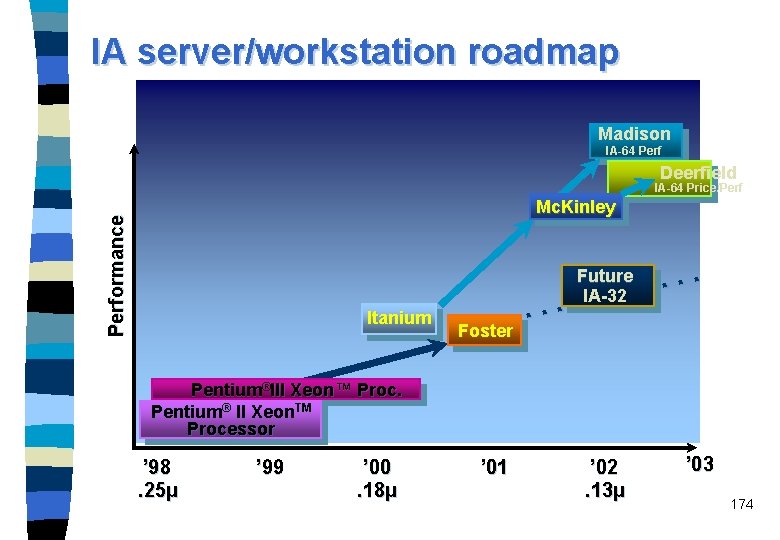
Pentium 4 offsprings n n Foster Pentium 4 with external L 3 cache and DDR-SDRAM support provided for server clock rate 1. 7 - 2 GHz to be launched in Q 2/2001 Northwood n 0. 13 µm technique n new 478 pin socket 132

VLIW or EPIC n VLIW (very long instruction word): Compiler packs a fixed number of instructions into a single VLIW instruction. The instructions within a VLIW instruction are issued and executed in parallel Example: High-end signal processors (TMS 320 C 6201) n EPIC (explicit parallel instruction computing): Evolution of VLIW Example: Intel’s IA-64, exemplified by the Itanium processor 133

VLIW (very long instruction word) processors use a long instruction word that contains a usually fixed number of operations that are fetched, decoded, issued, and executed synchronously. n All operations specified within a VLIW instruction must be independent of one another. n Some of the key issues of a (V)LIW processor: – (very) long instruction word (up to 1 024 bits per instruction), – each instruction consists of multiple independent parallel operations, – each operation requires a statically known number of cycles to complete, – a central controller that issues a long instruction word every cycle, – multiple FUs connected through a global shared register file. n 134

VLIW and superscalar n n n n Sequential stream of long instruction words. Instructions scheduled statically by the compiler. Number of simultaneously issued instructions is fixed during compile-time. Instruction issue is less complicated than in a superscalar processor. Disadvantage: VLIW processors cannot react on dynamic events, e. g. cache misses, with the same flexibility like superscalars. The number of instructions in a VLIW instruction word is usually fixed. Padding VLIW instructions with no-ops is needed in case the full issue bandwidth is not be met. This increases code size. More recent VLIW architectures use a denser code format which allows to remove the no-ops. VLIW is an architectural technique, whereas superscalar is a 135 microarchitecture technique.

EPIC: a paradigm shift n Superscalar RISC solution – Based on sequential execution semantics – Compiler’s role is limited by the instruction set architecture – Superscalar hardware identifies and exploits parallelism n EPIC solution – (the evolution of VLIW) – Based on parallel execution semantics – EPIC ISA enhancements support static parallelization – Compiler takes greater responsibility for exploiting parallelism – Compiler / hardware collaboration often resembles superscalar 136

EPIC: a paradigm shift n Advantages of pursuing EPIC architectures – Make wide issue & deep latency less expensive in hardware – Allow processor parallelism to scale with additional VLSI density n Architect the processor to do well with in-order execution – Enhance the ISA to allow static parallelization – Use compiler technology to parallelize program – However, a purely static VLIW is not appropriate for generalpurpose use 137

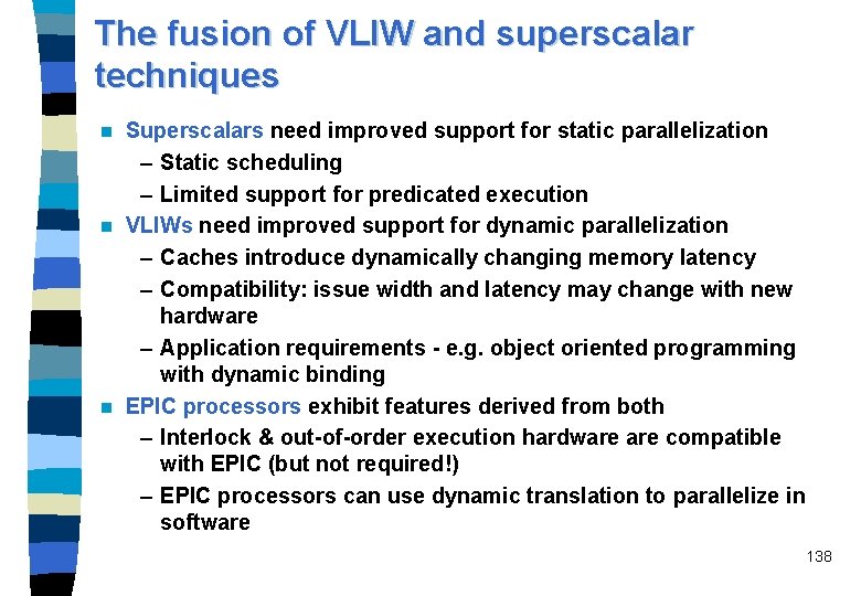
The fusion of VLIW and superscalar techniques Superscalars need improved support for static parallelization – Static scheduling – Limited support for predicated execution n VLIWs need improved support for dynamic parallelization – Caches introduce dynamically changing memory latency – Compatibility: issue width and latency may change with new hardware – Application requirements - e. g. object oriented programming with dynamic binding n EPIC processors exhibit features derived from both – Interlock & out-of-order execution hardware compatible with EPIC (but not required!) – EPIC processors can use dynamic translation to parallelize in software n 138

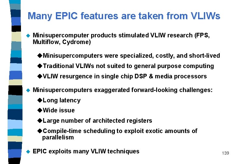
Many EPIC features are taken from VLIWs u Minisupercomputer products stimulated VLIW research (FPS, Multiflow, Cydrome) u. Minisupercomputers were specialized, costly, and short-lived u. Traditional VLIWs not suited to general purpose computing u. VLIW resurgence in single chip DSP & media processors u Minisupercomputers exaggerated forward-looking challenges: u. Long latency u. Wide issue u. Large number of architected registers u. Compile-time scheduling to exploit exotic amounts of parallelism u EPIC exploits many VLIW techniques 139

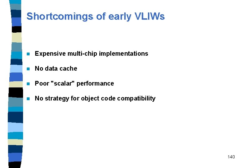
Shortcomings of early VLIWs n Expensive multi-chip implementations n No data cache n Poor "scalar" performance n No strategy for object code compatibility 140

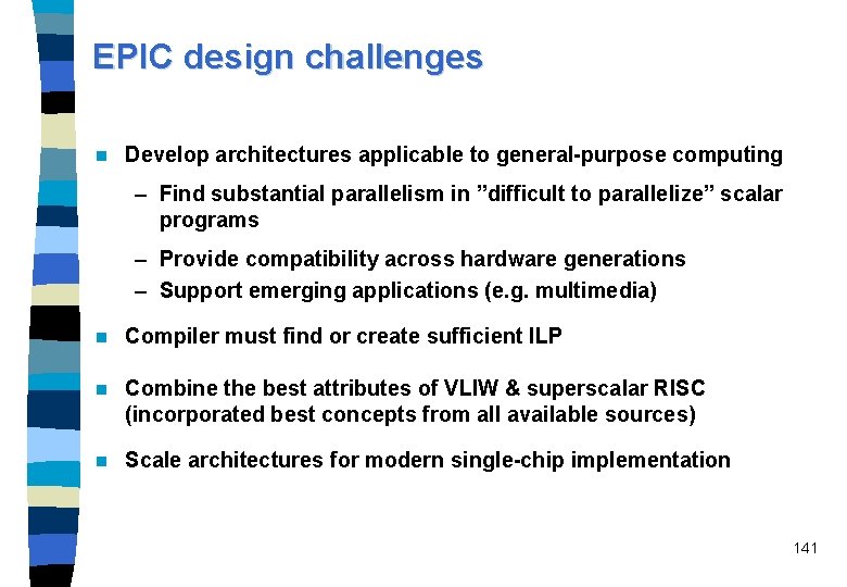
EPIC design challenges n Develop architectures applicable to general-purpose computing – Find substantial parallelism in ”difficult to parallelize” scalar programs – Provide compatibility across hardware generations – Support emerging applications (e. g. multimedia) n Compiler must find or create sufficient ILP n Combine the best attributes of VLIW & superscalar RISC (incorporated best concepts from all available sources) n Scale architectures for modern single-chip implementation 141

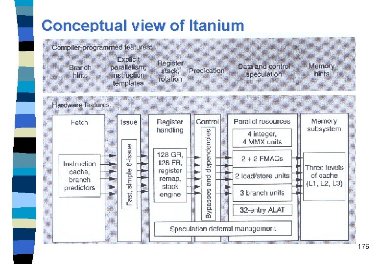
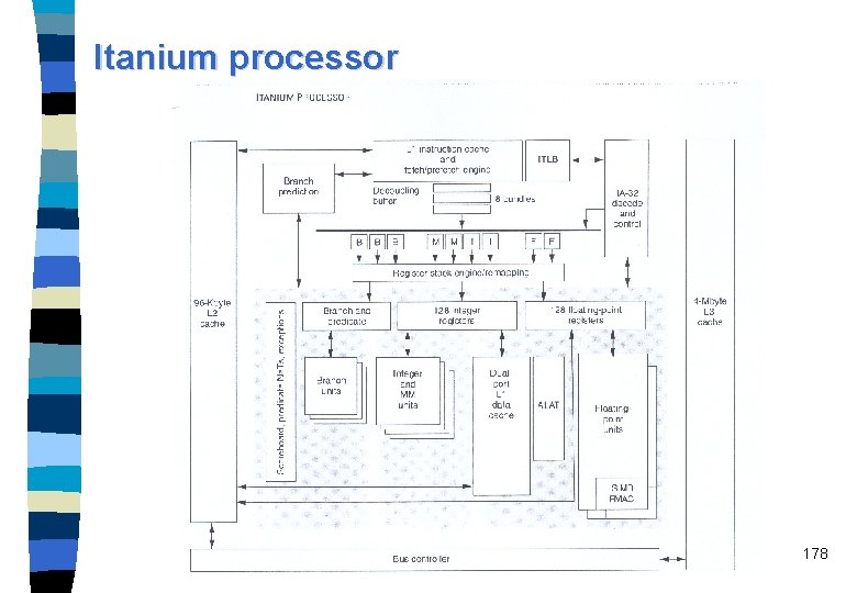
EPIC Processors, Intel's IA-64 ISA and Itanium Joint R&D project by Hewlett-Packard and Intel (announced in June 1994) n This resulted in explicitly parallel instruction computing (EPIC) design style: – specifying ILP explicit in the machine code, that is, the parallelism is encoded directly into the instructions similarly to VLIW; – a fully predicated instruction set; – an inherently scalable instruction set (i. e. , the ability to scale to a lot of FUs); – many registers; – speculative execution of load instructions n 142

IA-64 Architecture Unique architecture features & enhancements – Explicit parallelism and templates – Predication, speculation, memory support, and others – Floating-point and multimedia architecture n IA-64 resources available to applications – Large, application visible register set – Rotating registers, register stack engine n IA-32 & PA-RISC compatibility models n 143

Today’s architecture challenges n Performance barriers : – Memory latency – Branches – Loop pipelining and call / return overhead n Headroom constraints : – Hardware-based instruction scheduling • Unable to efficiently schedule parallel execution – Resource constrained • Too few registers • Unable to fully utilize multiple execution units n Scalability limitations : – Memory addressing efficiency 144

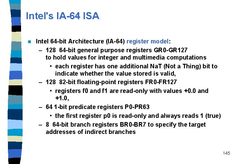
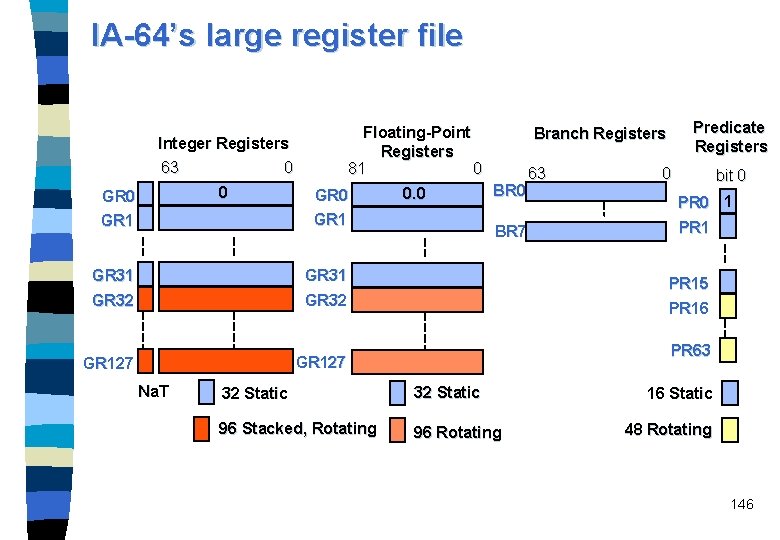
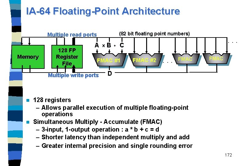
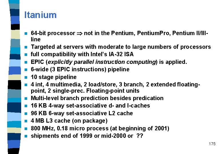
Intel's IA-64 ISA n Intel 64 -bit Architecture (IA-64) register model: – 128 64 -bit general purpose registers GR 0 -GR 127 to hold values for integer and multimedia computations • each register has one additional Na. T (Not a Thing) bit to indicate whether the value stored is valid, – 128 82 -bit floating-point registers FR 0 -FR 127 • registers f 0 and f 1 are read-only with values +0. 0 and +1. 0, – 64 1 -bit predicate registers P 0 -PR 63 • the first register p 0 is read-only and always reads 1 (true) – 8 64 -bit branch registers BR 0 -BR 7 to specify the target addresses of indirect branches 145

IA-64’s large register file Floating-Point Registers 81 0 Integer Registers 63 0 0 GR 1 GR 31 GR 32 GR 127 Na. T 0. 0 Predicate Registers Branch Registers BR 0 BR 7 63 0 bit 0 PR 0 1 PR 15 PR 16 PR 63 32 Static 96 Stacked, Rotating 96 Rotating 16 Static 48 Rotating 146

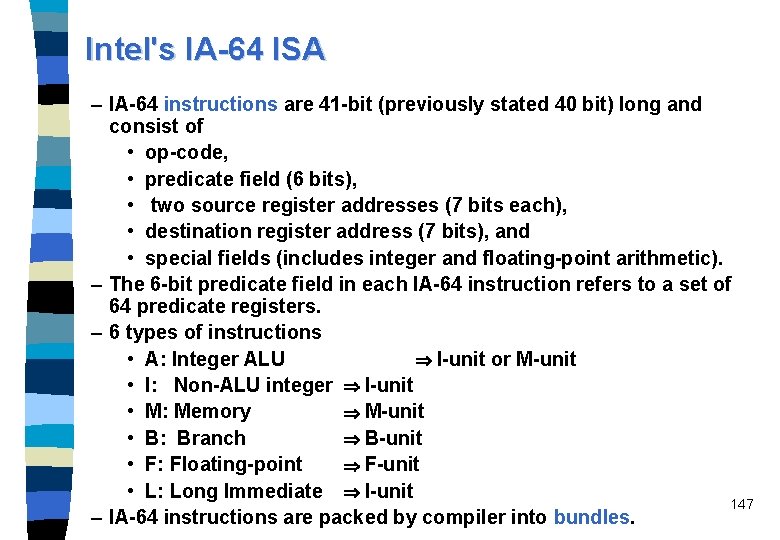
Intel's IA-64 ISA – IA-64 instructions are 41 -bit (previously stated 40 bit) long and consist of • op-code, • predicate field (6 bits), • two source register addresses (7 bits each), • destination register address (7 bits), and • special fields (includes integer and floating-point arithmetic). – The 6 -bit predicate field in each IA-64 instruction refers to a set of 64 predicate registers. – 6 types of instructions • A: Integer ALU I-unit or M-unit • I: Non-ALU integer I-unit • M: Memory M-unit • B: Branch B-unit • F: Floating-point F-unit • L: Long Immediate I-unit 147 – IA-64 instructions are packed by compiler into bundles.

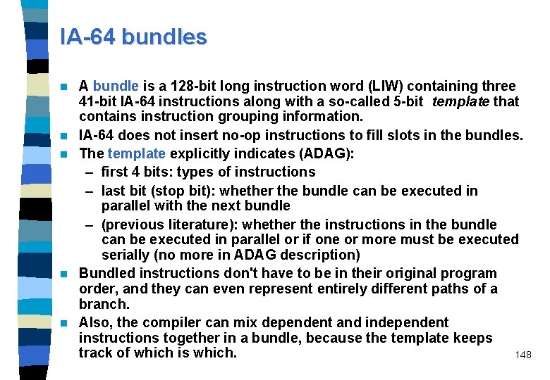
IA-64 bundles n n n A bundle is a 128 -bit long instruction word (LIW) containing three 41 -bit IA-64 instructions along with a so-called 5 -bit template that contains instruction grouping information. IA-64 does not insert no-op instructions to fill slots in the bundles. The template explicitly indicates (ADAG): – first 4 bits: types of instructions – last bit (stop bit): whether the bundle can be executed in parallel with the next bundle – (previous literature): whether the instructions in the bundle can be executed in parallel or if one or more must be executed serially (no more in ADAG description) Bundled instructions don't have to be in their original program order, and they can even represent entirely different paths of a branch. Also, the compiler can mix dependent and independent instructions together in a bundle, because the template keeps track of which is which. 148

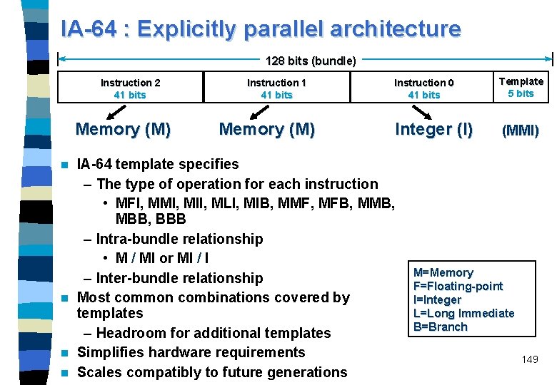
IA-64 : Explicitly parallel architecture 128 bits (bundle) Instruction 2 41 bits Memory (M) Instruction 1 41 bits Memory (M) Instruction 0 41 bits Template 5 bits Integer (I) (MMI) IA-64 template specifies – The type of operation for each instruction • MFI, MMI, MII, MLI, MIB, MMF, MFB, MMB, MBB, BBB – Intra-bundle relationship • M / MI or MI / I – Inter-bundle relationship n Most common combinations covered by templates – Headroom for additional templates n Simplifies hardware requirements n Scales compatibly to future generations n M=Memory F=Floating-point I=Integer L=Long Immediate B=Branch 149

IA-64 scalability n A single bundle containing three instructions corresponds to a set of three FUs. n If an IA-64 processor had n sets of three FUs each then using the template information it would be possible to chain the bundles to create instruction word of n bundles in length. n This is the way to provide scalability of IA-64 to any number of FUs. 150

Predication in IA-64 ISA n n n Branch prediction: paying a heavy penalty in lost cycles if mispredicted. IA-64 compilers uses predication to remove the penalties caused by mispredicted branches and by the need to fetch from noncontiguous target addresses by jumping over blocks of code beyond branches. When the compiler finds a branch statement it marks all the instructions that represent each path of the branch with a unique identifier called a predicate. IA-64 defines a 6 -bit field (predicate register address) in each instruction to store this predicate. 64 unique predicates available at one time. Instructions that share a particular branch path will share the same predicate. IA-64 also defines an advanced branch prediction mechanism for 151 branches which cannot be removed.

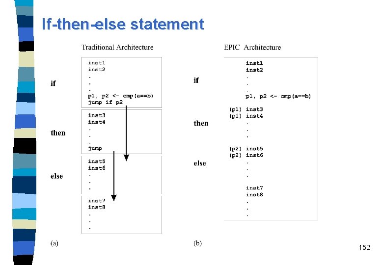
If-then-else statement 152

Predication in IA-64 ISA At run time, the CPU scans the templates, picks out the independent instructions, and issues them in parallel to the FUs. n Predicated branch: the processor executes the code for every possible branch outcome. n In spite of the fact that the processor has probably executed some instructions from both possible paths, none of the (possible) results is stored yet. n To do this, the processor checks predicate register of each of these instructions. – If the predicate register contains a 1, the instruction is on the TRUE path (i. e. , valid path), so the processor retires the instruction and stores the result. – If the register contains a 0, the instruction is invalid, so the processor discards the result. 153 n

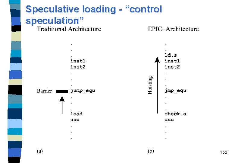
Speculative loading n n n Load data from memory well before the program needs it, and thus to effectively minimize the impact of memory latency. Speculative loading is a combination of compile-time and run-time optimizations. compiler-controlled speculation The compiler is looking for any instructions that will need data from memory and, whenever possible, hoists a load at an earlier point in the instruction stream, ahead of the instruction that will actually use the data. Today's superscalar processors: – load can be hoisted up to the first branch instruction which represents a barrier Speculative loading combined with predication gives the compiler more flexibility to reorder instructions and to shift loads above branches. 154

Speculative loading - “control speculation” 155

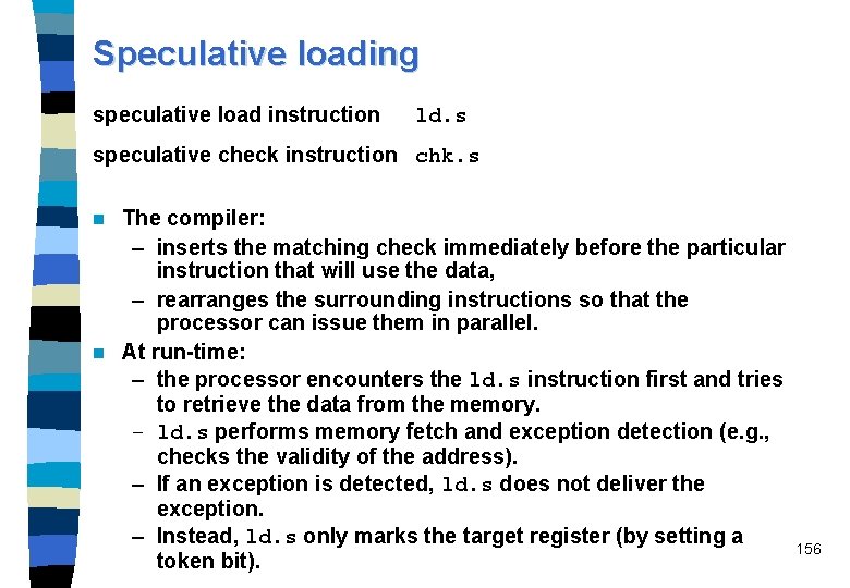
Speculative loading speculative load instruction ld. s speculative check instruction chk. s The compiler: – inserts the matching check immediately before the particular instruction that will use the data, – rearranges the surrounding instructions so that the processor can issue them in parallel. n At run-time: – the processor encounters the ld. s instruction first and tries to retrieve the data from the memory. – ld. s performs memory fetch and exception detection (e. g. , checks the validity of the address). – If an exception is detected, ld. s does not deliver the exception. – Instead, ld. s only marks the target register (by setting a token bit). n 156

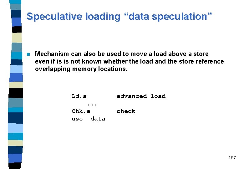
Speculative loading “data speculation” n Mechanism can also be used to move a load above a store even if is is not known whether the load and the store reference overlapping memory locations. Ld. a advanced load . . . Chk. a use data check 157

Speculative loading/checking n Exception delivery is the responsibility of the matching chk. s instruction. – When encountered, chk. s calls the operating system routine if the target register is marked (i. e, if the corresponding token bit is set), and does nothing otherwise. n Whether the chk. s instruction will be encountered may depend on the outcome of the branch instruction. Thus, it may happen that an exception detected by ld. s is never delivered. n Speculative loading with ld. s/chk. s machine level instructions resembles the TRY/CATCH statements in some high-level programming languages (e. g. , Java). 158

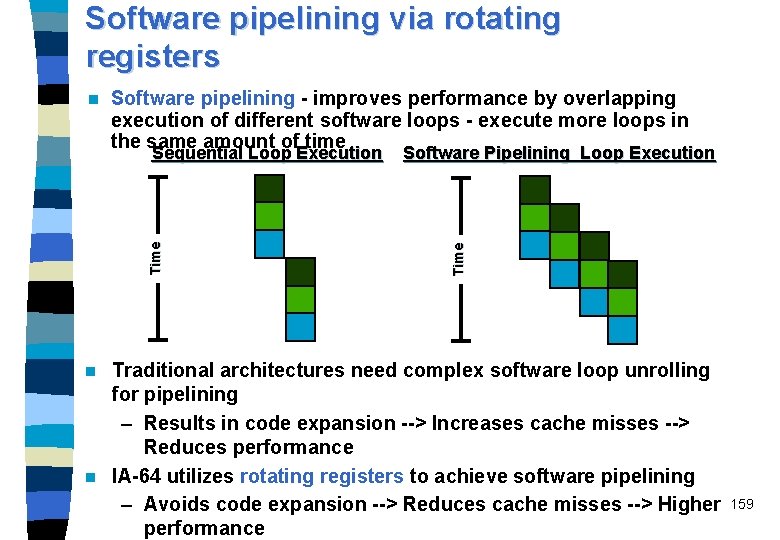
Software pipelining via rotating registers Software pipelining - improves performance by overlapping execution of different software loops - execute more loops in the same amount of time Time Sequential Loop Execution Software Pipelining Loop Execution Time n Traditional architectures need complex software loop unrolling for pipelining – Results in code expansion --> Increases cache misses --> Reduces performance n IA-64 utilizes rotating registers to achieve software pipelining – Avoids code expansion --> Reduces cache misses --> Higher performance n 159

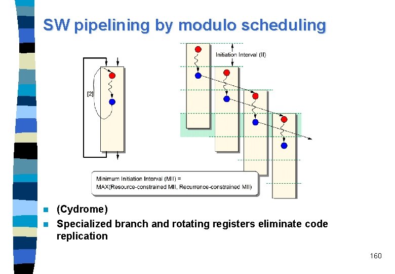
SW pipelining by modulo scheduling (Cydrome) n Specialized branch and rotating registers eliminate code replication n 160

SW pipelining by register rotation Rotating registers – Floating-point: f 32 -f 127 – General-purpose: g 32 -g 127; can be set by an alloc imm instruction – Predicate: p 16 -p 63 n Additional registers needed: – Current frame marker CFM: describes state of the general register stack plus three register rename base values used in register rotation: • rr. pr (6 bit) • rr. fr (7 bit) • rr. gr (7 bit) – within the “Application registers”: • loop count LC (64 bit register): decremented by countedloop-type branches • Epilog count EC (6 -bit registers): for counting the epilog stages n 161

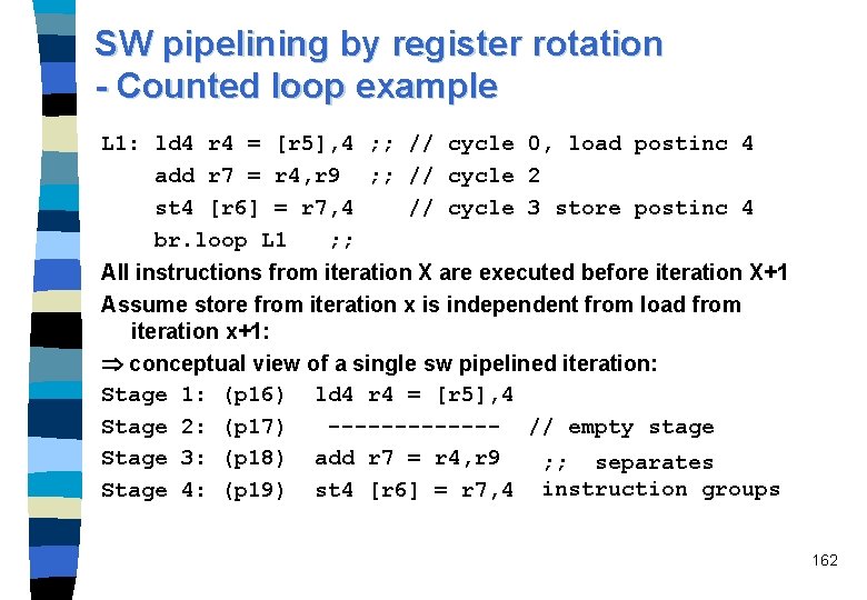
SW pipelining by register rotation - Counted loop example L 1: ld 4 r 4 = [r 5], 4 ; ; // cycle 0, load postinc 4 add r 7 = r 4, r 9 ; ; // cycle 2 st 4 [r 6] = r 7, 4 // cycle 3 store postinc 4 br. loop L 1 ; ; All instructions from iteration X are executed before iteration X+1 Assume store from iteration x is independent from load from iteration x+1: conceptual view of a single sw pipelined iteration: Stage 1: (p 16) ld 4 r 4 = [r 5], 4 Stage 2: (p 17) ------- // empty stage Stage 3: (p 18) add r 7 = r 4, r 9 ; ; separates Stage 4: (p 19) st 4 [r 6] = r 7, 4 instruction groups 162

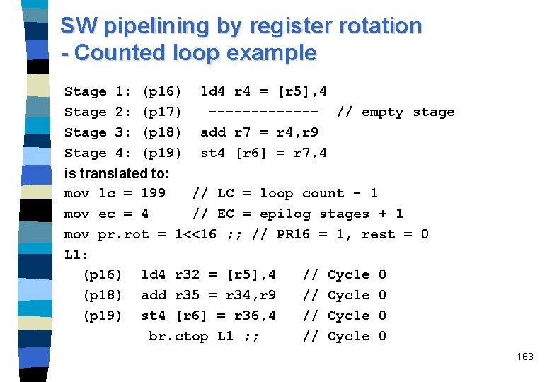
SW pipelining by register rotation - Counted loop example Stage 1: 2: 3: 4: (p 16) (p 17) (p 18) (p 19) ld 4 r 4 = [r 5], 4 ------- // empty stage add r 7 = r 4, r 9 st 4 [r 6] = r 7, 4 is translated to: mov lc = 199 // LC = loop count - 1 mov ec = 4 // EC = epilog stages + 1 mov pr. rot = 1<<16 ; ; // PR 16 = 1, rest = 0 L 1: (p 16) ld 4 r 32 = [r 5], 4 // Cycle 0 (p 18) add r 35 = r 34, r 9 // Cycle 0 (p 19) st 4 [r 6] = r 36, 4 // Cycle 0 br. ctop L 1 ; ; // Cycle 0 163

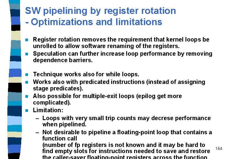
SW pipelining by register rotation - Optimizations and limitations Register rotation removes the requirement that kernel loops be unrolled to allow software renaming of the registers. n Speculation can further increase loop performance by removing dependence barriers. n Technique works also for while loops. n Works also with predicated instructions (instead of assigning stage predicates). n Also possible for multiple-exit loops (epilog get more complicated). n Limitation: – Loops with very small trip counts may decrese performance when pipelined. – Not desirable to pipeline a floating-point loop that contains a function call (number of fp registers is not known and it may be hard to find empty slots for instructions needed to save and restore n 164

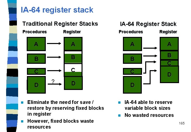
IA-64 register stack Traditional Register Stacks IA-64 Register Stack Procedures Register A A B B B C C C D D D ? Eliminate the need for save / restore by reserving fixed blocks in register n However, fixed blocks waste resources n A Register A B C D D IA-64 able to reserve variable block sizes n No wasted resources n 165

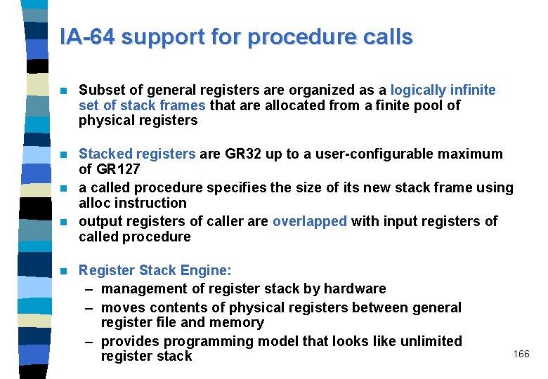
IA-64 support for procedure calls n Subset of general registers are organized as a logically infinite set of stack frames that are allocated from a finite pool of physical registers Stacked registers are GR 32 up to a user-configurable maximum of GR 127 n a called procedure specifies the size of its new stack frame using alloc instruction n output registers of caller are overlapped with input registers of called procedure n n Register Stack Engine: – management of register stack by hardware – moves contents of physical registers between general register file and memory – provides programming model that looks like unlimited register stack 166

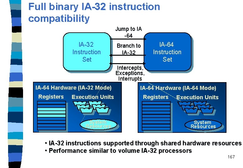
Full binary IA-32 instruction compatibility Jump to IA -64 IA-32 Instruction Set IA-64 Instruction Set Branch to IA-32 Intercepts, Exceptions, Interrupts IA-64 Hardware (IA-32 Mode) Registers Execution Units System Resources IA-64 Hardware (IA-64 Mode) Registers Execution Units System Resources • IA-32 instructions supported through shared hardware resources • Performance similar to volume IA-32 processors 167

Full binary compatibility for PA-RISC Transparency: – Dynamic object code translator in HP-UX automatically converts PA-RISC code to native IA-64 code – Translated code is preserved for later reuse n Correctness: – Has passed the same tests as the PA-8500 n Performance: – Close PA-RISC to IA-64 instruction mapping – Translation on average takes 1 -2% of the time Native instruction execution takes 98 -99% – Optimization done for wide instructions, predication, speculation, large register sets, etc. – PA-RISC optimizations carry over to IA-64 n 168

Delivery of streaming media Audio and video functions regularly perform the same operation on arrays of data values – IA-64 manages its resources to execute these functions efficiently • Able to manage general register’s as 8 x 8, 4 x 16, or 2 x 32 bit elements • Multimedia operands/results reside in general registers n IA-64 accelerates compression / decompression algorithms – Parallel ALU, Multiply, Shifts – Pack/Unpack; converts between different element sizes. n Fully compatible with – IA-32 MMXä technology, – Streaming SIMD Extensions and – PA-RISC MAX 2 n 169

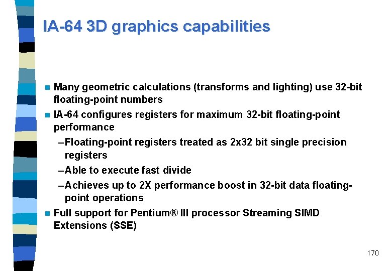
IA-64 3 D graphics capabilities n Many geometric calculations (transforms and lighting) use 32 -bit floating-point numbers n IA-64 configures registers for maximum 32 -bit floating-point performance – Floating-point registers treated as 2 x 32 bit single precision registers – Able to execute fast divide – Achieves up to 2 X performance boost in 32 -bit data floatingpoint operations n Full support for Pentium® III processor Streaming SIMD Extensions (SSE) 170

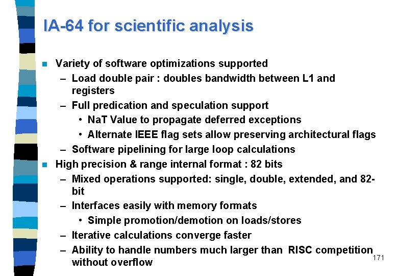
IA-64 for scientific analysis Variety of software optimizations supported – Load double pair : doubles bandwidth between L 1 and registers – Full predication and speculation support • Na. T Value to propagate deferred exceptions • Alternate IEEE flag sets allow preserving architectural flags – Software pipelining for large loop calculations n High precision & range internal format : 82 bits – Mixed operations supported: single, double, extended, and 82 bit – Interfaces easily with memory formats • Simple promotion/demotion on loads/stores – Iterative calculations converge faster – Ability to handle numbers much larger than RISC competition 171 without overflow n

IA-64 Floating-Point Architecture (82 bit floating point numbers) Multiple read ports Memory 128 FP Register File A X B + C FMAC #1 Multiple write ports . . . FMAC #2 . . . FMAC D 128 registers – Allows parallel execution of multiple floating-point operations n Simultaneous Multiply - Accumulate (FMAC) – 3 -input, 1 -output operation : a * b + c = d – Shorter latency than independent multiply and add – Greater internal precision and single rounding error n 172

Memory support for high performance technical computing Scientific analysis, 3 D graphics and other technical workloads tend to be predictable & memory bound n IA-64 data pre-fetching of operations allows for fast access of critical information – Reduces memory latency impact n IA-64 able to specify cache allocation – Cache hints from load / store operations allow data to be placed at specific cache level – Efficient use of caches, efficient use of bandwidth n 173

IA server/workstation roadmap Madison IA-64 Perf Deerfield IA-64 Price/Performance Mc. Kinley Itanium Foster . . . Future IA-32 . . . Pentium®III Xeon™ Proc. Pentium® II Xeon. TM Processor ’ 98. 25µ ’ 99 ’ 00. 18µ ’ 01 ’ 02. 13µ ’ 03 174

Itanium n n n n 64 -bit processor not in the Pentium, Pentium. Pro, Pentium II/IIIline Targeted at servers with moderate to large numbers of processors full compatibility with Intel’s IA-32 ISA EPIC (explicitly parallel instruction computing) is applied. 6 -wide (3 EPIC instructions) pipeline 10 stage pipeline 4 int, 4 multimedia, 2 load/store, 3 branch, 2 extended floatingpoint, 2 single-prec. Floating-point units Multi-level branch prediction besides predication 16 KB 4 -way set-associative d- and I-caches 96 KB 6 -way set-associative L 2 cache 4 MB L 3 cache (on package) 800 MHz, 0. 18 micro process (at beginning of 2001) shipments end of 1999 or mid-2000 or ? ? 175

Conceptual view of Itanium 176

Itanium processor core pipeline ROT: instruction rotation pipelined access of the large register file: WDL: word line decode: REG: register read DET: exception detection (~retire stage) 177

Itanium processor 178

Itanium die plot 179

Itanium vs. Willamette (P 4) Itanium announced with 800 MHz n P 4 announced with 1. 2 GHz n P 4 may be faster in running IA-32 code than Itanium running IA 64 code n Itanium probably won‘t compete with contemporary IA-32 processors n but Intel will complete the Itanium design anyway n n Intel hopes for the Itanium successor Mc. Kinley which will be out only one year later 180