UNITIII Class Diagram and Composite Structure Diagram P


 connection between object")


, can")
 is produced or computed from other")


 q. UML permits a class to inherit from multiple superclasses, although")


 • A composition indicates a strong ownership and coincident lifetime of")


 Associations can also be objects themselves, called link classes or an")


- Slides: 122
UNIT-III Class Diagram and Composite Structure Diagram P. P. Mahale
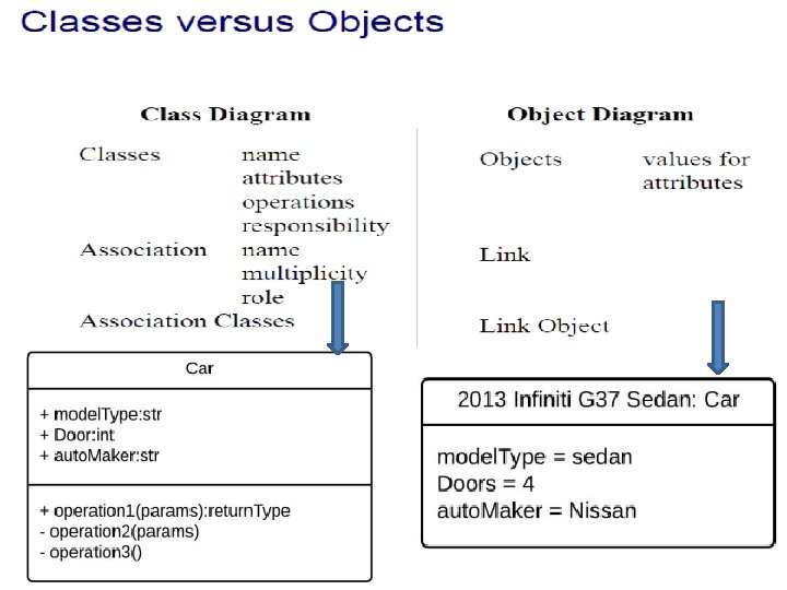
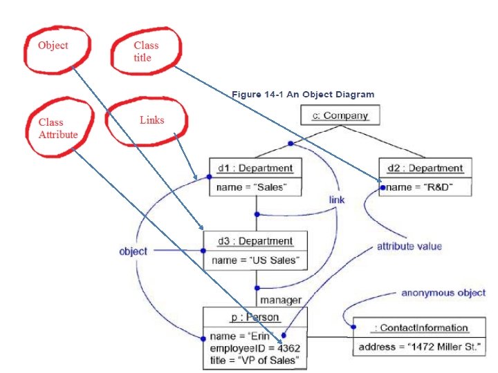
Object Diagrams • Terms and Concepts An object diagram is a diagram that shows a set of objects and their relationships at a point in time. Graphically, an object diagram is a collection of vertices and arcs • Common Properties § Objects § Links • Common Uses To model object structures
Object Diagrams Common Modeling Techniques Modeling Object Structures To model an object structure, • Identify the mechanism you'd like to model. • A mechanism represents some function or behavior of the part of the system you are modeling that results from the interaction of a society of classes, interfaces, and other things. • For each mechanism, identify the classes, interfaces, and other elements that participate in this collaboration. • Identify the relationships among these things, as well.
• Consider one scenario that walks through this mechanism. Freeze that scenario at a moment in time, and render each object that participates in the mechanism. • Expose the state and attribute values of each such object, as necessary, to understand the scenario. • Similarly, expose the links among these objects, representing instances of associations among them.
Object Diagrams
Object Diagrams
q Link: - A link is a physical or conceptual (semantic) connection between object instances. q Messages : - It is a specification of communication among objects that convey information with expectation that activity will ensure - Model actions like: 1. Call – invoke operation on an object 2. return: - return value to caller 3. send 4. create 5. destroy
q sequencing : - Sequence is formed by stream of messages
Class Diagrams q When writing software you are constantly making design decisions: ü what classes hold references to other classes, ü which class "owns" some other class, and so on. q Class diagrams provide a way to capture this "physical" structure of a system.
Classes v A class represents a group of things that have common state and behavior. UML suggests that the class name: • • Start with a capital letter Be centered in the top compartment Be written in a boldface font Be written in italics if the class is abstract
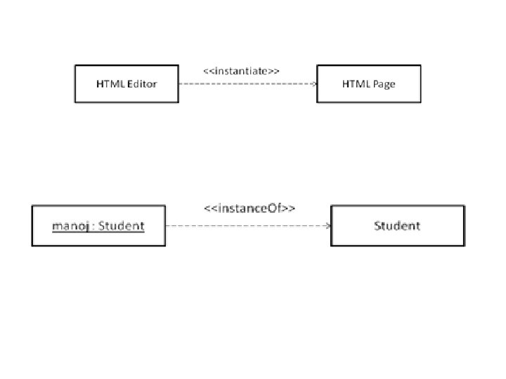
ü Objects An object is an instance of a class.
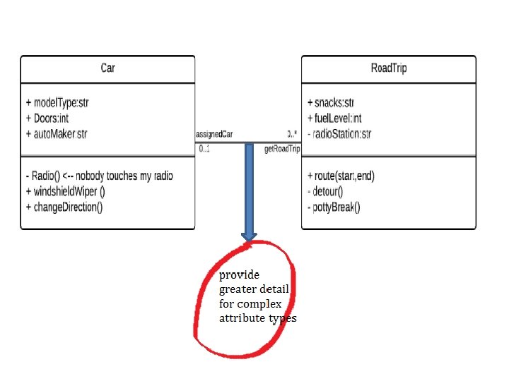
Attributes • Details of a class are represented as attributes. • Attributes can be simple primitive types (integers, floating-point numbers, etc. ) or relationships to other complex objects. • An attribute can be shown using two different notations: inlined or relationships between classes. • In addition, notation is available to show such things as multiplicity, uniqueness, and ordering.
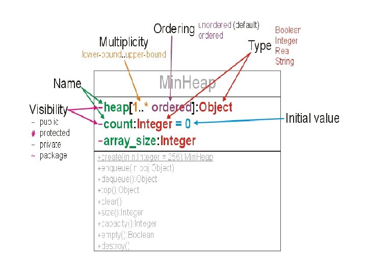
Inline attributes • UML refers to inlined attributes as attribute notation. Inlined attributes use the following notation: visibility / name : type multiplicity = default {property strings and constraints } visibility : : = {+|-|#|~} multiplicity : : = [lower. . upper]
q The syntax elements are: • Visibility: Indicates the visibility of the attribute. Use the following symbols: +, -, #, or ~ for public, private, protected, or package, respectively • / : Indicates the attribute is derived. • Name: Is a noun or short phrase naming the attribute. Typically the first letter is lowercase, and the first letter of each subsequent word is capitalized. • Type: Is the type of the attribute as another classifier, typically a class, interface, or built-in type like int.
• Multiplicity: Specifies how many instances of the attribute's type are referenced by this attribute. • Default: Is the default value of the attribute. • property strings: Is a collection of properties, or tags, that can be attached to attributes. These are typically context-specific and denote such things as ordering or uniqueness. They are surrounded by {} and separated by commas. See "Properties. “ • Constraints: Are one or more restrictions placed on an attribute. They may be natural language or use a formal grammar such as the OCL.
ü Attributes by Relationship • The relationship notation results in a larger class diagram, but it can provide greater detail for complex attribute types. • The relationship notation also conveys exactly how the attribute is contained within a class
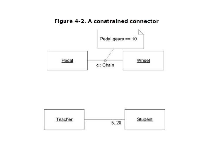
Figure 2 -5. Relationship notation using constraints
Derived Attribute • The derived notation, which is the leading forward slash (/), can be used as an indicator to the implementer that the attribute may not be strictly necessary.
Derived property is property which value (or values) is produced or computed from other information, for example, by using values of other properties.
Attribute Multiplicity • The multiplicity of an attribute specifies how many instances of the attribute's type are created when the owning class is instantiated.
ü Ordering • An attribute with a multiplicity greater than 1 can be specified to be ordered. • If the attribute is ordered, the elements must be stored sequentially.
ü Uniqueness • In addition to being ordered, an attribute with multiplicity greater than 1 may be required to be unique Figure: - Unique multiplicity
ü Attribute Properties The common properties defined by UML are: • read. Only: Specifies that the attribute may not be modified once the initial value is set. • Union: Specifies that the attribute type is a union of the possible values for this attribute. • Subsets <attribute-name>: Specifies that this attribute type is a subset of all the valid values for the given attribute. • redefine <attribute-name>: Specifies that this attribute acts as an alias for the given attribute. • Composite: Specifies that this attribute is part of a whole part relationship with the classifier
ü Constraints • Constraints represent restrictions placed on an element. Fig- Example of inlined and note constraints
ü Static attributes • Static attributes are attributes of the class rather than of an instance of the class.
Operations • Operations are features of classes that specify how to invoke a particular behavior. à syntax: visibility name ( parameters ) : return-type {properties} where parameters are written as: direction parameter_name : type [ multiplicity ] = default_value { properties }
• • • Visibility Name return-type Properties Parameter syntax elements are: • Direction: An optional part of the syntax that indicates how a parameter is used by an operation. It is one of in, inout, or return. in states that the parameter is passed to the operation by the caller. • • • parameter_name: Is a noun or noun phrase naming the parameter. Type: Is the type of the parameter. Multiplicity: default_value • Properties: Specifies any parameter-related properties and is specified between curly braces.
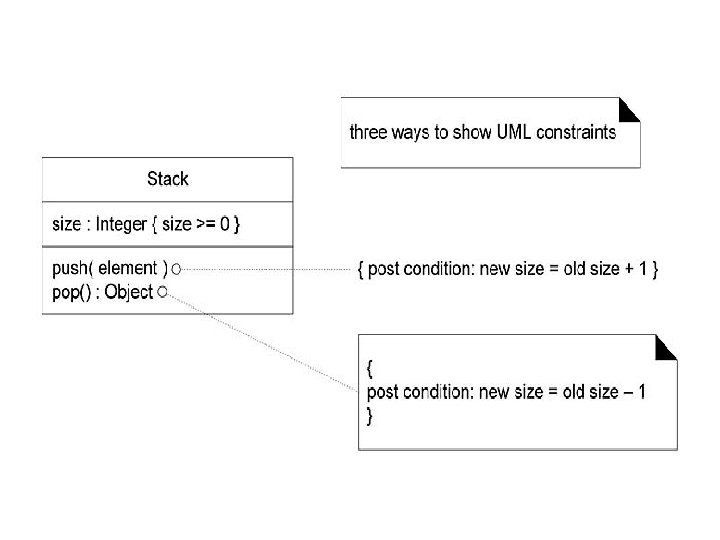
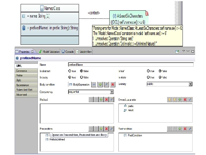
Ø Operation Constraints • An operation may have several constraints associated with it that help define how the operation interacts with the rest of the system. Precondition: • Preconditions capture what the state of the system must be before an operation can be invoked.
Postconditions • Postconditions capture guarantees about the state of the system after an operation has executed.
Body condition: • An operation may have a body Condition that constrains the return value.
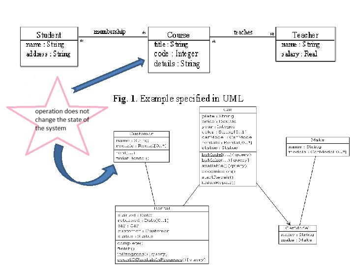
Query operations: • An operation may be declared as a query operation if the implementation of the operation doesn't modify the owning class in any way.
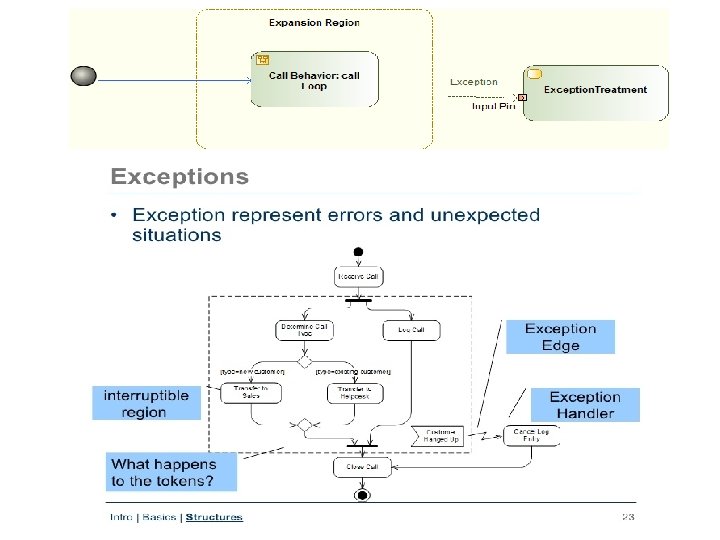
Exceptions: • Exceptions are often used to reflect abnormal conditions that are part of common operations such as creating a new file, opening a socket, or dividing by zero.
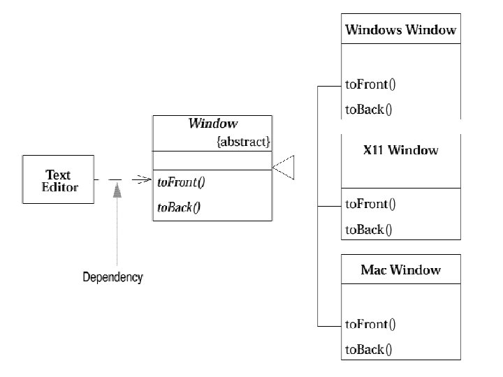
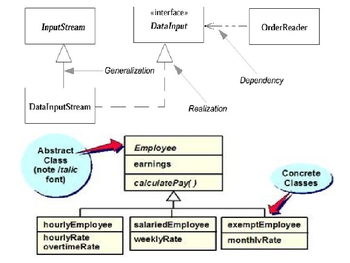
Abstract Classes • An abstract class is typically a class that provides an operation signature, but no implementation; however, you can have an abstract class that has no operations at all. • An abstract class is useful for identifying common functionality across several types of objects.
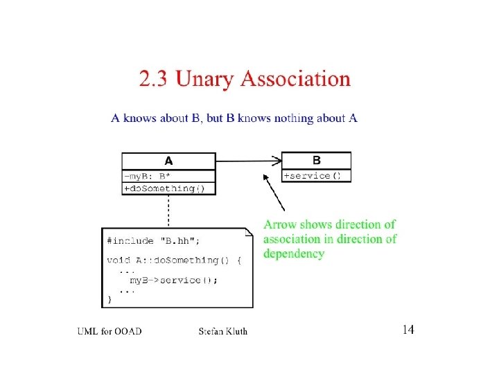
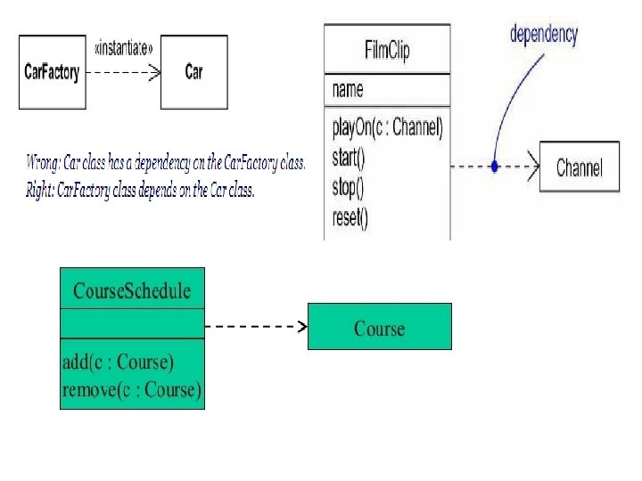
Relationships • Classes in isolation would not provide much insight into how a system is designed. UML provides several ways of representing relationships between classes. 1. Dependency • The weakest relationship between classes is a dependency relationship. Dependency between classes means that one class uses, or has knowledge of, another class. • Dependencies are typically read as ". . . uses a. . . ". • A dependency relationship indicates that changes to independent model element can cause changes in another model element. The supplier model element is independent because a change in the client does not affect it.
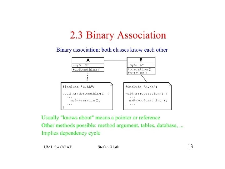
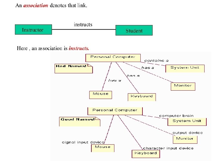
2. Association • Associations are stronger than dependencies and typically indicate that one class retains a relationship to another class over an extended period of time. • Associations are typically read as ". . . has a. . . ".
2. 1 Navigability • Associations have explicit notation to express navigability. If you can navigate from one class to another, you show an arrow in the direction of the class you can navigate to. • We can constrain the association relationship by defining the navigability of the association. Here, a Router object requests services from a DNS object by sending messages to (invoking the operations of) the server. • The direction of the association indicates that the server has no knowledge of the Router Domain. Name. Server
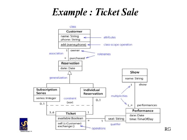
2. 2. Naming an association • Associations may be adorned with several symbols to add information to your model.
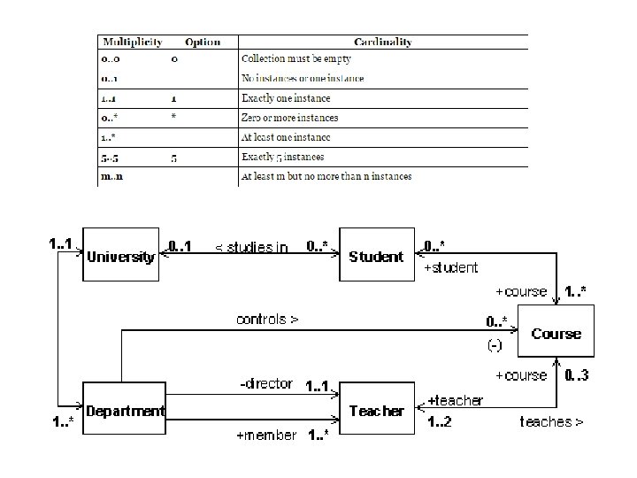
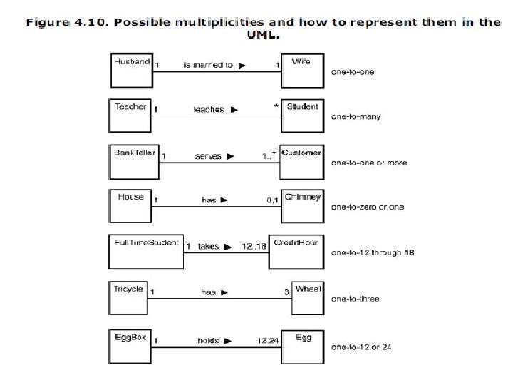
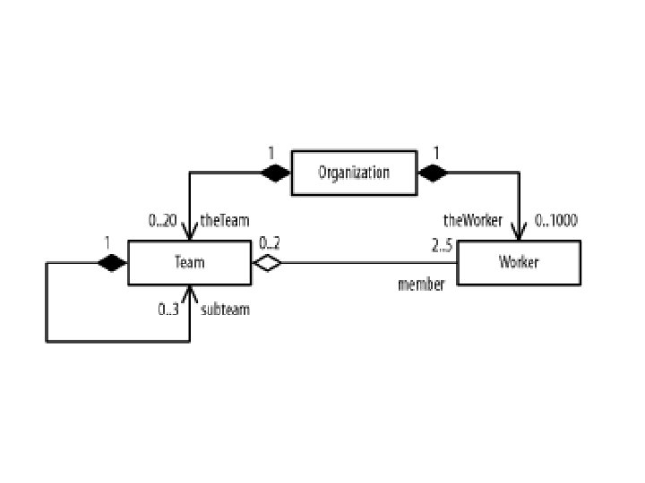
• Multiplicity: • Multiplicity specifies how many instances of one class may relate to a single instance of an associated class • Multiplicity constraints can only be used with binary associations. Candidate keys have to be used in n-ary relationships. • "how many" is called the multiplicity of an association's role, and is written as an expression that evaluates to a range of values or an explicit value • You can show a multiplicity of exactly one (1), zero or one (0. . 1), many (0. . *), or one or more (1. . *). You can even state an exact number (for example, 3).
Link attribute: • It is a property of link in an association Ex: - access permission is an attribute of accessible by. • Symbol is box attached to association link by loop
Role name: • A role names is a behavior of an entity participating in a particular context.
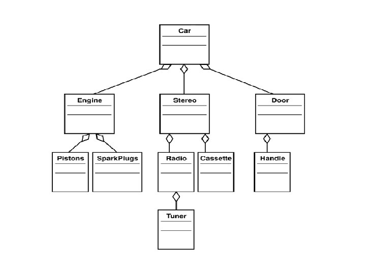
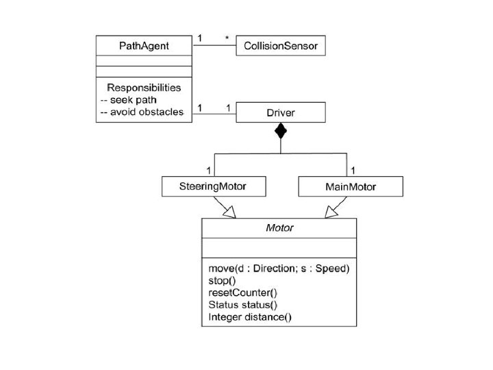
Aggregation • An aggregation is special type of association that represents a "part-of" relationship. Aggregations are transitivity and anti-symmetric • An aggregation is a special case of association denoting a “consists of” hierarchy. • The aggregate is the parent class, the components are the children class. 60
• A line joins a whole to a component, with an open diamond on the line near the whole. • We want to model a "whole/part" relationship, in which one class represents a larger thing (the "whole"), which consists of smaller things (the "parts"). • This kind of relationship is called aggregation, which represents a "has-a" relationship • An object of the whole has objects of the part.
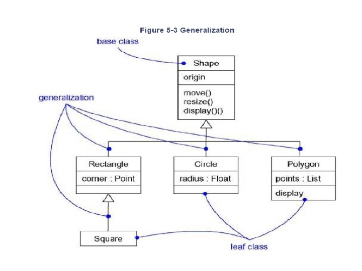
• GENERALIZATION - A generalization is a relationship between a class and one or more refined versions of that class. - generalization is a specialization/generalization relationship in which objects of the specialized element (the child) are substitutable for objects of the generalized element (the parent). - Graphically, a generalization relationship is denoted as a solid line with a hollow arrowhead pointing to the parent, - Generalization is sometimes called an "is-a-kind-of" relationship
Generalization Relationships Person • A generalization connects a subclass to its superclass. It denotes an inheritance of attributes and behavior from the superclass to the subclass and indicates Student subclass superclass. Software Design (UML) a specialization of the more in the general
Generalization Relationships (Cont’d) q. UML permits a class to inherit from multiple superclasses, although some programming languages (e. g. , Java) do not permit multiple inheritance. Student Employee Teaching. Assistant Software Design (UML)
Generalization Button Cancel. Button Zone. Button 66
• The inheritance relationship helps in managing the complexity by ordering objects within trees of classes with increasing levels of abstraction. • Notation used is solid line with arrowhead, shown below. • Generalization and specialization are points of view that are based on inheritance hierarchies.
Composition • A solid diamond denote composition, • A strong form of aggregation • Components cannot exist without the aggregate. Ticket. Machine 3 Zone. Button 69
Composition • • This is a strong form of aggregation It expresses the stronger coupling between the classes The owner is explicitly responsible for creation and deletion of the part Any deletion of whole is considered to cascade its part The aggregate has a filled diamond at its end Window Client Area 70
Association Relationships (Cont’d) • A composition indicates a strong ownership and coincident lifetime of parts by the whole (i. e. , they live and die as a whole). Compositions are denoted by a filled-diamond adornment on the association. 1 Window 1 1 1. . * Software Design (UML) Scrollbar Titlebar Menu
1. 2. 3.
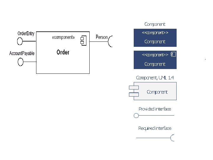
Interfaces • An interface is a named set of operations that specifies the behavior <<interface>> Control. Panel of objects without showing their inner structure. It can be rendered in the model by a one- or two-compartment rectangle, with the stereotype <<interface>> above the interface name. Software Design (UML)
Interface Realization Relationship • A realization relationship <<interface>> Control. Panel connects a class with an specifier interface that supplies its behavioral specification. It is implementation Vending Machine rendered by a dashed line with a hollow towards the specifier. Software Design (UML) triangle
6. Association Classes • Often the relationship between two elements isn't a simple structural connection.
Association Relationships (Cont’d) Associations can also be objects themselves, called link classes or an association classes. Registration model. Number serial. Number warrenty. Code Product Warranty Software Design (UML)
7. Association Qualifiers • A qualifier is typically an attribute of the target element, though this isn't required. You show a qualifier by placing a small rectangle between the association and the source element. • Draw the name of the qualifier (usually the name of an attribute) in the rectangle. Figure 2 -30. An association qualifier
• Ordering: - Ordering is an inherent part of association - Ordered set of object on the “many” end of association is indicated by writing {ordered} next to multiplicity dot for the role - it’s a special type of constraint - • Qualification: • It is an association attribute whose values partition the set of objects related to an object across an association. • We denote a qualifier as a small rectangle attached to the end of an association, placing the attributes in the rectangle, as the figure shows
4. Interface Specifier • Interface is a collection of operations that are used to specify a service of a class or a component; every class may realize many interfaces. • For example, in the vocabulary of a human resources system, a Person class may realize many interfaces: IManager, IEmployee, Iofficer • As Figure shows, you can model the relationship between a supervisor and her workers with a one-to-many
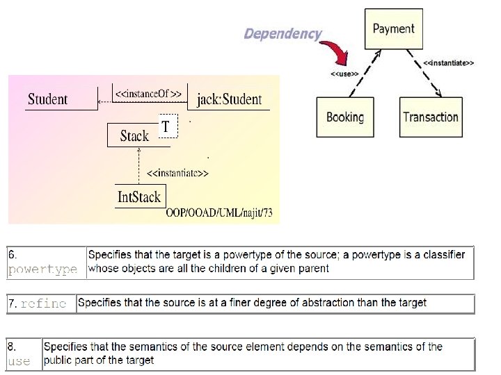
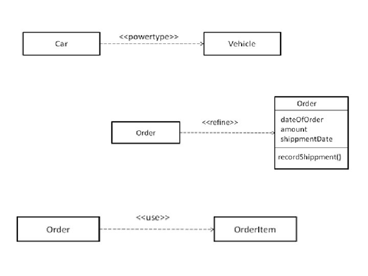
Advanced Relationships § Dependency • Dependency is a using relationship, specifying that a change in the specification of one thing (for example, class Set. Top. Controller) may affect another thing that uses it (for example, class Channel. Iterator), but not necessarily the reverse
• Graphically, a dependency is rendered as a dashed line, directed to the thing that is depended on. • Apply dependencies when you want to show one thing using another. • There are eight stereotypes that apply to dependency relationships among classes and objects in class diagrams.
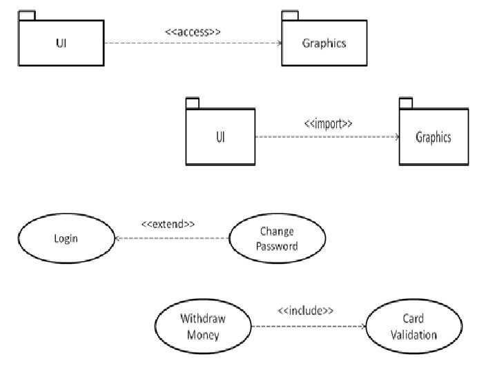
• There are two stereotypes that apply to dependency relationships among packages. • Two stereotypes apply to dependency relationships among use cases:
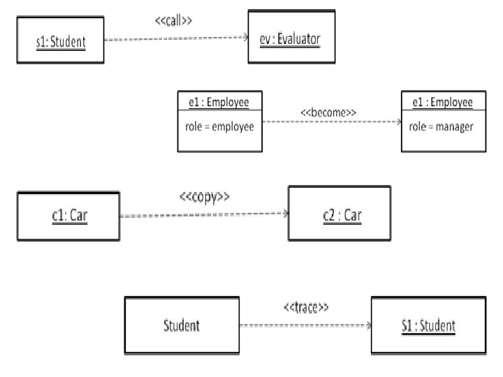
• Three stereotypes when modeling interactions among objects. • One stereotype you'll encounter in the context of state machines is • One stereotype that you'll encounter in the context of organizing the elements of your system into subsystems and models is
§ Generalization • Generalization is a relationship between a general thing (called the superclass or parent) and a more specific kind of that thing (called the subclass or child).
• UML defines one stereotype and four constraints that may be applied to generalization relationships - There is the one stereotype. - There are four standard constraints that apply to generalization relationships.
7. Constraints • UML defines five constraints that may be applied to association relationships. • First, you can distinguish if the association is real or conceptual. • There is one constraint for managing related sets of associations:
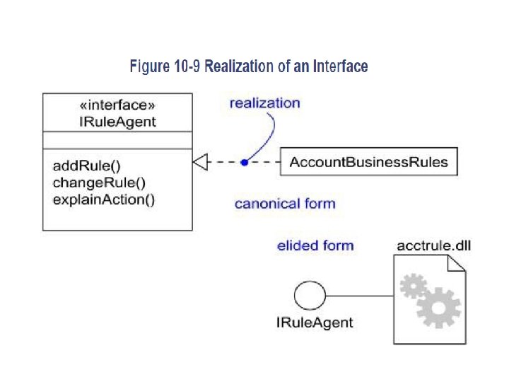
8. Realization • A realization is a semantic relationship between classifiers in which one classifier specifies a contract that another classifier guarantees to carry out. • Graphically, a realization is rendered as a dashed directed line with a large open arrowhead pointing to the classifier that specifies the contract. • You'll use realization in two circumstances: in the context of interfaces and in the context of collaborations. • You can represent realization in two ways: in the canonical form (using the interface stereotype and the dashed directed line with a large open arrowhead) and in an elided form (using the interface lollipop notation).
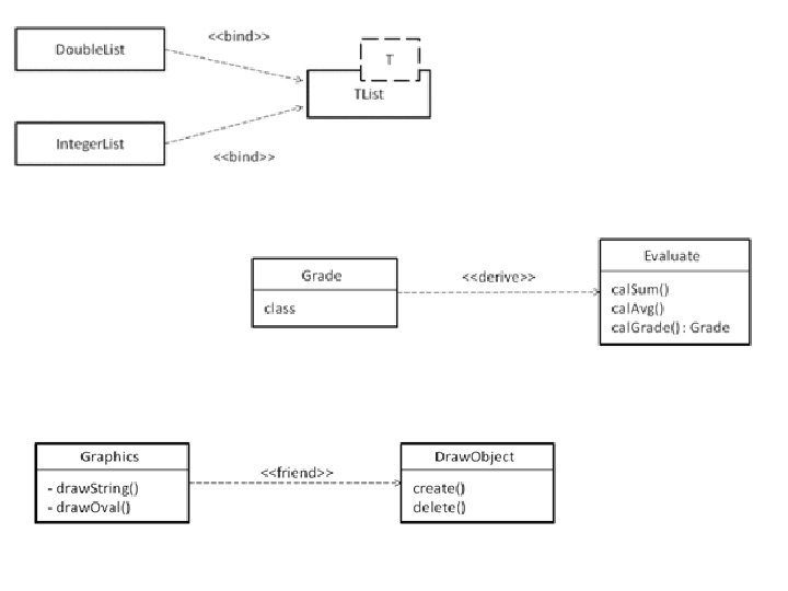
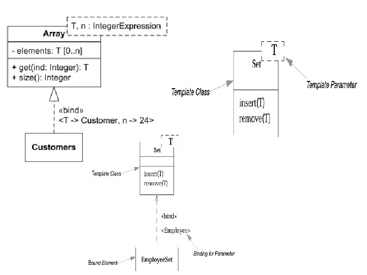
Templates Classes • A template is a parameterized element. you can write template classes, each of which defines a family of classes • Template includes slots for classes, objects, and values, and these slots serve as the template's parameters. • You can't use a template directly; you have to instantiate it first. Instantiation involves binding these formal template parameters to actual ones. • Most common use of template classes is to specify containers that can be instantiated for specific elements, making them type-safe
• For example, the following C++ code fragment declares a parameterized Map class. template<class Item, class Value, int Buckets> class Map { public: virtual Boolean bind(const Item&, const Value&); virtual Boolean is. Bound(const Item&) const; . . . }; You might then instantiate this template to map Customer objects to Order objects. m : Map<Customer, Order, 3>; • Denote a template class just as you do an ordinary class, but with an additional dashed box in the upper right corner of the class icon, which lists the template parameters.
• You can model the instantiation of a template class in two ways. • First, you can do so implicitly, by declaring a class whose name provides the binding. • Second, you can do so explicitly, by using a dependency stereotyped as bind, which specifies that the source instantiates the target template using the actual parameters.
Class Diagrams Terms and Concepts A class diagram is a diagram that shows a set of classes, interfaces, and collaborations and their relationships. Graphically, a class diagram is a collection of vertices and arcs. Common Properties A class diagram is just a special kind of diagram and shares the same common properties as do all other diagrams a name and graphical content that are a projection into a model. What distinguishes a class diagram from all other kinds of diagrams is its particular content.
Contents Class diagrams commonly contain the following things: • Classes • Interfaces • Collaborations • Dependency, generalization, and association relationships Like all other diagrams, class diagrams may contain notes and constraints. Common Uses You use class diagrams to model the static design view of a system. When you model the static design view of a system, you'll typically use class diagrams in one of three ways. 1. To model the vocabulary of a system 2. To model simple collaborations 3. To model a logical database schema
Common Modeling Techniques Modeling Simple Collaborations To model a collaboration, ü Identify the mechanism you'd like to model. ü For each mechanism, identify the classes, interfaces and other collaborations that participate in this collaboration. ü Identify the relationships among these things, as well. ü Use scenarios to walk through these things. ü Be sure to populate these elements with their contents.
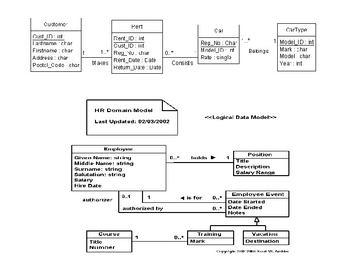
Modeling a Logical Database Schema To model a schema, • Identify those classes in your model whose state must transcend the lifetime of their applications. • Create a class diagram that contains these classes and mark them as persistent (a standard tagged value). You can define your own set of tagged values to address database-specific details. • Expand the structural details of these classes. • Watch for common patterns that complicate physical database design • Consider also the behavior of these classes by expanding operations that are important for data access and data integrity. • Where possible, use tools to help you transform your logical design into a physical design.
Figure 8 -3 Modeling a Schema
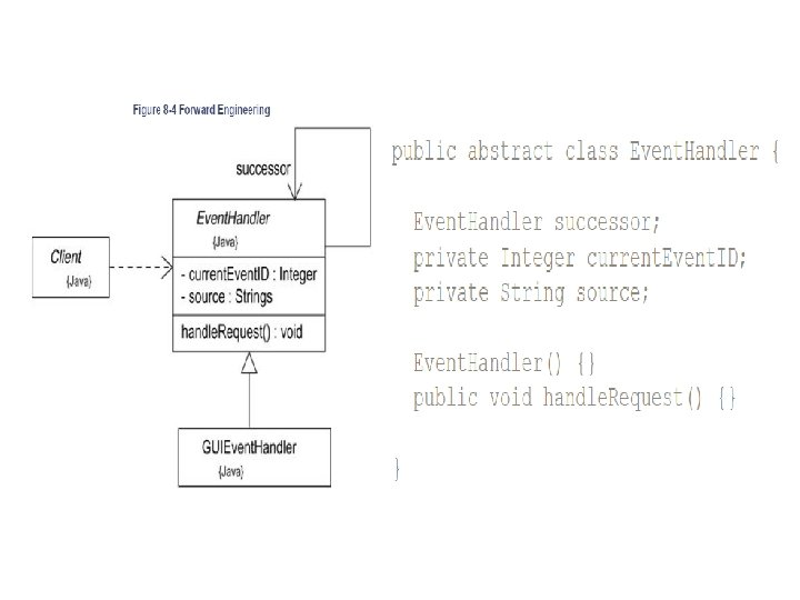
Forward and Reverse Engineering • Forward engineering is the process of transforming a model into code through a mapping to an implementation language. To forward engineer a class diagram, • Identify the rules for mapping to your implementation language or languages of choice. • Depending on the semantics of the languages you choose, you may have to constrain your use of certain UML features. • Use tagged values to specify your target language. • Use tools to forward engineer your models.
• Reverse engineering is the process of transforming code into a model through a mapping from a specific implementation language. To reverse engineer a class diagram, • Identify the rules for mapping from your implementation language or languages of choice. • Using a tool, point to the code you'd like to reverse engineer. • Using your tool, create a class diagram by querying the model.
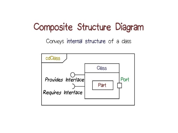
Composite Structures Diagram • A structure is a set of interconnected elements that exist at runtime to collectively provide some piece of functionality. • UML defines several symbols to capture the relationships and communications between elements in an internal structure.
1. Connectors • Connectors represent communication links between instances of classes participating in an internal structure. • You can provide name and type information for a connector using the following format: name: classname where: • name= Is the name of the connector. The name can be used later in collaborations to reference this connector. • Classname= Is the name of an association this connector represents.
2. Ports • A port is a way to offer functionality from a composite structure without exposing the internal details of how that functionality is realized.
2. 1. Required and provided interfaces • Required interfaces show what the owning classifier may ask of its environment through a given port. • Provided interfaces show what functionality a classifier exposes to the environment.
2. 2. Realizing port implementations • If the classifier owning the port provides the implementation of the functionality itself, the port is considered a behavioral port. • On the other hand, if the functionality is realized by internal elements, you link the connector to internal classifiers that provide the implementation. Figure 4 -7. A port linked to an internal implementation
2. 3. Multiple connectors UML 2. 0 allows you to have multiple connectors leading from a port to different internal elements.
2. 4. Port multiplicity A classifier may specify multiplicity for a port like any other element. Simply place the desired number of port instances in brackets after the port name and type (if present).
2. 5. Port typing • In practice, when a port is instantiated, it is represented by a classifier that realizes the provided interfaces. • Any communication with this interaction point simply passes the information to internal classifiers that realize the behavior. • UML 2. 0 allows you to specify the type of a port using classes to provide more sophisticated behavior.
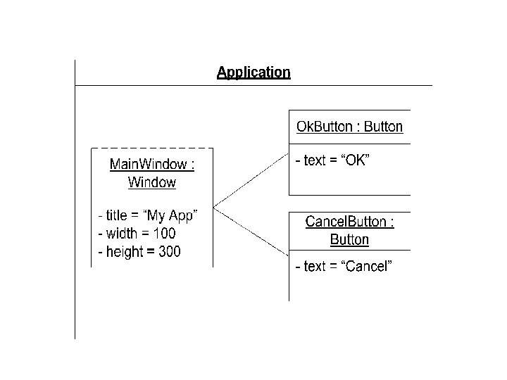
• Structured Classes and Properties
• Figure 4 -12. The Application, Window, and Button relationships as a composite structure