UNITIII Class Diagram and Composite Structure Diagram 08

 Object Diagram: a. Terms")


 connection between object")


 We can indicate the multiplicity of an association by adding multiplicity")
 The example indicates that every Instructor has one or more Students:")
 We can also indicate the behavior of an object in an")
 We can also name the association. membership Student 1. . *")
 We can specify dual associations. member of 1. . * Student")
 We can constrain the association relationship by defining the navigability of")
 Associations can also be objects themselves, called link classes or an")
 A class can have a self association. next Linked. List. Node")
 We can model objects that contain other objects by way of")
 A composition indicates a strong ownership and coincident lifetime of parts")


 UML permits a class to inherit from multiple superclasses, although some")


![Interface Services <<interface>> Control. Panel get. Choices : Choice[] make. Choice (c : Choice)](https://slidetodoc.com/presentation_image_h2/f388f42d24a0b6b9a2e0e45e189af98e/image-48.jpg "Interface Services <<interface>> Control. Panel get. Choices : Choice[] make. Choice (c : Choice)")


- Slides: 115
UNIT-III
Class Diagram and Composite Structure Diagram (08 Hrs, 16 Marks) Object Diagram: a. Terms and Concepts: Common Properties, Contents, Common Uses b. Common Modeling Techniques: Modeling Object Structures Class Diagram: c. Classes, Attributes, Operations, Abstract Classes d. Relationships: Dependency, Association, Aggregation, Composition, Generalization, Association Classes, Association Qualifiers e. Advanced Relationships: Stereotypes on Dependency, Stereotypes and Constraints on Generalization, Constraints on Association, Realization f. Interfaces g. Templates h. Class Diagram: Common Properties, Contents, Common Uses i. Common Modeling Techniques : Modeling Simple Collaborations, Modeling a Logical Database Schema j. Forward and Reverse Engineering Composite Structures Diagram: k. Connectors, Ports, Structured classes and Properties
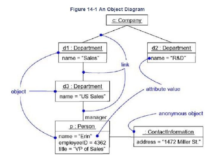
OBJECT DIAGRAM • Object diag. is a diagram that shows a set of object & their relationships at a point in time • Graphically it is a collection of vertices & edges • It’s a structural model & construct static aspect of system through forward & reverse engineering • template for describing how a particular set of objects relate to each other Instance diagram describes object instances
q Properties of object diagram - Show set of objects & their relationships q. Content of object diagram 1. 2. - Object diagram contain Object Links It may also contain notes & constraint , package or subsystem q Use of object diagram : - Model static view Support functional requirement of system i. e. service system should provide to end user Model object structure
- Identify mechanism like to model - Identify classes , interfaces - Expose state & attribute value of each object as necessary to understand scenario - Expose link among objects representing instance of association q object interaction - Interaction is a behavior that comprises a set of message exchanged among object - Interaction model dynamic aspect of collaboration - 2 –way of interaction 1. Emphasizing it’s time ordering of messages 2. Emphasizing it’s sequence of message
q Link: - A link is a physical or conceptual (semantic) connection between object instances. q Messages : - It is a specification of communication among objects that convey information with expectation that activity will ensure - Model actions like: 1. Call – invoke operation on an object 3. send 2. return: - return value to caller 4. create 5. destroy
q sequencing : - Sequence is formed by stream of messages
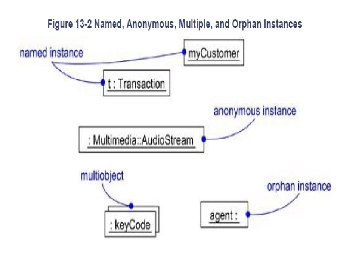
Advanced structural modeling § Instances: - It is concrete manifestation of abstraction to which set of operation may be applied & have state to store effect of operation Ø Abstraction & instances: - Instances are always tied to abstraction Ø Names: - every instance must have name that distinguish from other - Name is a textual string
§ Standard element: - Standard stereotype that apply to dependency relationship among object & classes 1. instanceof: - specifies that client object is an instance of the specifier classifier 2. Instantiate : - specifies that client class create instanceof supplier class • 2 –stereotype relate to object that apply to message & transitions 1. become: - specifies that same object as the supplier but at later time & with possibly different value , state & rules 2. Copy : - specifies that client object is an exact but independent copy of supplier
ACTIVE OBJECT - They are part of process or thread & represent root of flow of control - We can declare instance of active objects as - active objects is an object that own process / thread & can initiate control activity - Denoted as rectangle with thick lines
• When u draw active class or object in UML - Show only those attribute, opeartion & signal that are important in understanding that abstraction in context - Explicitly show all operation synchronization properties
Class diagrams • Class is an abstraction of system that are part of your vocabulary • Attributes and operations are specified for classes.
• Class : - A class describes a group of objects with similar properties (attributes), common behavior(operations), common relationships to other objects, and common semantics - Attributes and operations are specified for classes. - Class membership can be defined in two ways: implicitly by rule or explicitly - A class can have class attributes and class operations • Attribute: - An attribute is (represents) a data value which is held by the objects in a class. An attribute should be a pure data value, not an object.
• Operation & methods: - An operation is a function or transformation that may be applied to or by objects in a class. The same operation may be defined for several different classes. - Ex: open, close, hide operation on window - Same operation may apply to different classes , it is known as polymorphic - An operation is the implementation of a service that can be requested from any object of the class to affect behavior • Graphically, operations are listed in a compartment just below the class attributes. Operations may be drawn showing only their names
- Method: A method is the implementation of an operation for a class. The choice of which method is invoked it solely determined by the target object. • Link & association : - A link is a physical or conceptual connection between object instances. Links are order tuples Ex: - john works for a company - An association describes a group of links with common structure and common semantics. - Attributes and operations can be specified for associations. Basically, this allows one to treat an association as a class - Associations can have role names associated each class connection. - links in an association can be ordered
Association Relationships If two classes in a model need to communicate with each other, there must be link between them. An association denotes that link. Student Instructor Software Design (UML)
Association Relationships (Cont’d) We can indicate the multiplicity of an association by adding multiplicity adornments to the line denoting the association. The example indicates that a Student has one or more Instructors: Student 1. . * Software Design (UML) Instructor
Association Relationships (Cont’d) The example indicates that every Instructor has one or more Students: Student Instructor 1. . * Software Design (UML)
Association Relationships (Cont’d) We can also indicate the behavior of an object in an association (i. e. , the role of an object) using rolenames. teaches Student learns from 1. . * Software Design (UML) Instructor
Association Relationships (Cont’d) We can also name the association. membership Student 1. . * Software Design (UML) Team
Association Relationships (Cont’d) We can specify dual associations. member of 1. . * Student Team 1 president of Software Design (UML) 1. . *
Association Relationships (Cont’d) We can constrain the association relationship by defining the navigability of the association. Here, a Router object requests services from a DNS object by sending messages to (invoking the operations of) the server. The direction of the association indicates that the server has no knowledge of the Router Domain. Name. Server Software Design (UML)
Association Relationships (Cont’d) Associations can also be objects themselves, called link classes or an association classes. Registration model. Number serial. Number warrenty. Code Product Warranty Software Design (UML)
Association Relationships (Cont’d) A class can have a self association. next Linked. List. Node Software Design (UML) previous
Association Relationships (Cont’d) We can model objects that contain other objects by way of special associations called aggregations and compositions. An aggregation specifies a whole-part relationship between an aggregate (a whole) and a constituent part, where the part can exist independently from the aggregate. Aggregations are denoted by a hollow-diamond adornment on the association. Engine Car Transmission Software Design (UML)
Association Relationships (Cont’d) A composition indicates a strong ownership and coincident lifetime of parts by the whole (i. e. , they live and die as a whole). Compositions are denoted by a filled-diamond adornment on the association. 1 Window 1 1 1. . * Software Design (UML) Scrollbar Titlebar Menu
Dependency Relationships A dependency indicates a semantic relationship between two or more elements. The dependency from Course. Schedule to Course exists because Course is used in both the add and remove operations of Course. Schedule Course add(c : Course) remove(c : Course) Software Design (UML)
Instance • An instance represents a phenomenon. • The name of an instance is underlined and can contain the class of the instance. • The attributes are represented with their values. 30
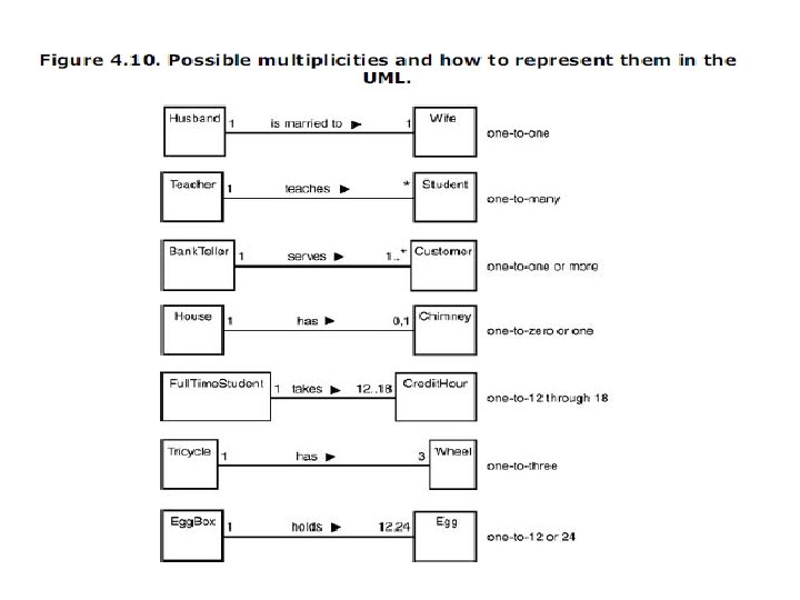
• Multiplicity: - Multiplicity specifies how many instances of one class may relate to a single instance of an associated class - Multiplicity constraints can only be used with binary associations. Candidate keys have to be used in n-ary relationships. -"how many" is called the multiplicity of an association's role, and is written as an expression that evaluates to a range of values or an explicit value -You can show a multiplicity of exactly one (1), zero or one (0. . 1), many (0. . *), or one or more (1. . *). You can even state an exact number (for example, 3).
• Link attribute: - It is a property of link in an association Ex: - access permission is an attribute of accessible by. - Symbol is box attached to association link by loop - file accessible by user Access permission • Role name: - A role names is a behavior of an entity participating in a particular context.
• Ordering: - Ordering is an inherent part of association Ordered set of object on the “many” end of association is indicated by writing {ordered} next to multiplicity dot for the role - it’s a special type of constraint - • Qualification: • It is an association attribute whose values partition the set of objects related to an object across an association. • We denote a qualifier as a small rectangle attached to the end of an association, placing the attributes in the rectangle, as the figure shows
Aggregation • An aggregation is special type of association that represents a "part-of" relationship. Aggregations are transitivity and anti-symmetric • An aggregation is a special case of association denoting a “consists of” hierarchy. • The aggregate is the parent class, the components are the children class. • We want to model a "whole/part" relationship, in which one class represents a larger thing (the "whole"), which consists of smaller things (the "parts"). This kind of relationship is called aggregation, which represents a "has-a" relationship • an object of the whole has objects of the part. 35
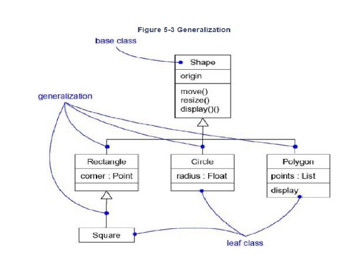
• A line joins a whole to a component, with an open diamond on the line near the whole. • GENERALIZATION & INHERITANCE - A generalization is a relationship between a class and one or more refined versions of that class. - generalization is a specialization/generalization relationship in which objects of the specialized element (the child) are substitutable for objects of the generalized element (the parent). - Graphically, a generalization relationship is denoted as a solid line with a hollow arrowhead pointing to the parent, - Generalization is sometimes called an "is-a-kind-of" relationship
Generalization Relationships Person Student A generalization connects a subclass to its superclass. It denotes an inheritance of attributes and behavior from the superclass to the subclass and indicates a specialization in the subclass of the more general superclass. Software Design (UML)
Generalization Relationships (Cont’d) UML permits a class to inherit from multiple superclasses, although some programming languages (e. g. , Java) do not permit multiple inheritance. Student Employee Teaching. Assistant Software Design (UML)
Generalization Button Cancel. Button Zone. Button 39
• Inheritance: - inheritance is a mechanism for sharing attributes and operations using a generalization relationship. - The dynamic model of a superclass is inherited by its subclasses. A subclass can have its own states.
• The inheritance relationship helps in managing the complexity by ordering objects within trees of classes with increasing levels of abstraction. Notation used is solid line with arrowhead, shown below. • Generalization and specialization are points of view that are based on inheritance hierarchies.
Composition • A solid diamond denote composition, • A strong form of aggregation • Components cannot exist without the aggregate. 43
Composition Ticket. Machine 3 Zone. Button 44
COMPOSITION: • • This is a strong form of aggregation It expresses the stronger coupling between the classes The owner is explicitly responsible for creation and deletion of the part Any deletion of whole is considered to cascade its part The aggregate has a filled diamond at its end Window Client Area 45
DEPENDENCY: • Dependency is semantic connection between dependent and independent model elements. • This association is unidirectional and is shown with dotted arrowhead line. • In the following example it shows the dependency relationship between client and server. • The client avails services provided by server so it should have semantic knowledge of server. • The server need not know about client. Client Server 46
Interfaces <<interface>> Control. Panel An interface is a named set of operations that specifies the behavior of objects without showing their inner structure. It can be rendered in the model by a one- or twocompartment rectangle, with the stereotype <<interface>> above the interface name. Software Design (UML)
Interface Services <<interface>> Control. Panel get. Choices : Choice[] make. Choice (c : Choice) get. Selection : Selection Interfaces do not get instantiated. They have no attributes or state. Rather, they specify the services offered by a related class. Software Design (UML)
Interface Realization Relationship <<interface>> Control. Panel specifie r implementatio n Vending. Machine A realization relationship connects a class with an interface that supplies its behavioral specification. It is rendered by a dashed line with a hollow triangle towards the specifier. Software Design (UML)
What is Cardinality? : • • Definition: Number of instances of each class involved in the dialogue is specified by cardinality. Common multiplicity values: Symbol Meaning 1 One and only one 0. . 1 Zero or one M…N From M to N (natural integer) 0. . * From zero to any positive integer 1. . * From one to any positive integer • Also thought can be given about navigability to every applicable relationship. 50
• Constraints: - Constraints are functional relationships between entities of an object model. - A constraint shows the functional relationship between two objects at the same time or between two values of the same object at different times - A constraint between values of an object over time is called an invariant - With constraints, you can add new semantics or change existing rules. - A constraint specifies conditions that must be held true for the model to be wellformed.
- The term entity includes objects, classes, attributes, links, and associations, constraint restrict values that entities can assume Ex: - no employee salary can exceed the salary of employees boss - A constraint is denoted as a string enclosed by brackets and placed near the associated element. • Candidate key : - It is a minimal set of attribute that uniquely identifies object or link - Class or association may have one or more candidate key, each of which may have different combination & no. of attribute - Object ID is always a candidate key for class - It’s a logical concept constrain the instance in a class or multiplicity in a class many-many asso. 1 -many person own stock company - company {candidate key: person, company} {candidate key: person}
• - - Multiple inheritance It has more than one super class & inherit feature from all parent Mixing of information from 2 or more sources Advantage: greater power in specifying classes & increase reuse Class with more than one super class is called join class Accidental Multiple inheritance : - instance of join class is inherently an instance of all ancestor of join class
• Abstract class: - A class that cannot be directly instantiated. But descent classes have direct instances - An abstract class can not be a leaf class on a generalization hierarchy - A concrete class is a class that will have members - A subclass may add new operations and attributes. This is called extension - subclass may constrain an ancestor attribute. This is called restriction • Constraint on link: - Here notation {ordered} indicate that element of many end of association have an explicit order that must be preserved - Constraint provide one criterion for measuring quality of an object model Constraint denoted by braces { }
• General constraint: - it must be expressed with natural language or equation Should draw a dotted line between classes involved in constraint & specify details in braces • Derived object, link & attribute : - Derived object : - define as a function of one or more object, which may be derived - Notation for derived entity: - slash (/) , diagonal line (on the corner of the class box on an association line , or in front of attribute) fig: derived attribute
• • - Name: Every class have name-textual string Attribute: Named property of class that describe a range of values • • - Operation : Implementation of service that can be requested from any object Responsibilities: It is an contract or an obligation of a class Drawn in a separate compartment at bottom of class icon
Classes & relationships • Things can connect logically/physically by relationships • in OOMD 3 -kind of relationships 1. Dependencies 2. association 3. generalization 1. dependencies: - It is using relationship for change of specification of one thing to other Ex: pipe size depend on flow of water Course. Schedule Course add(c : Course) remove(c : Course)
2. Generalization - called as "is-a-kind-of" relationship - relationship in which objects of the specialized element (the child) are substitutable for objects of the generalized element (the parent). - is denoted as a solid line with a hollow arrowhead pointing to the parent
3. association: - If two classes in a model need to communicate with each other, there must be link between them. - An association denotes that link.
• Name: - We can also name the association. membership Student 1. . * Team • Role: - A role names is a behavior of an entity participating in a particular context • Multiplicity - Multiplicity specifies how many instances of one class may relate to a single instance of an associated class
• Aggregation: - An aggregation is special type of association that represents a "part-of" relationship
Common uses of class diagram: Static design view of system To model vocabulary of system To model simple collaboration To model logical d/b schema To model forward & reverse engg. Common modeling techniques Modeling simple collaboration: Each class works in collaboration with other To model collaboration: Identify mechanism you would like to model. mechanism represent function or behavior of part of system you are modeling 2. for each mechanism identify relationship among them • • 1. 1.
3. Discover part of model that were missing & semantically wrong 4. Populate these element with their content
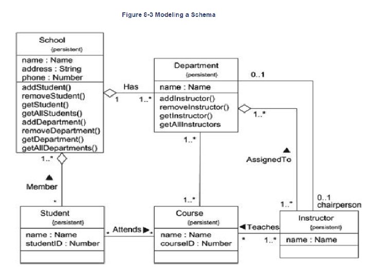
2. Modeling a logical database : - Many modeling system have persistent object , means that they can be stored in database for later retrieval - to model schema 1. Identify those classes in model whose state transcend the lifetime of their application 2. create class diag. that contain these classes & work them as persistent. Define own set of tagged value to address d/b detail 3. expand structural detail of class. 4. watch for common pattern that complicate physical d/b design 5. consider behavior of classes by expanding operation that are important for data access & integrity
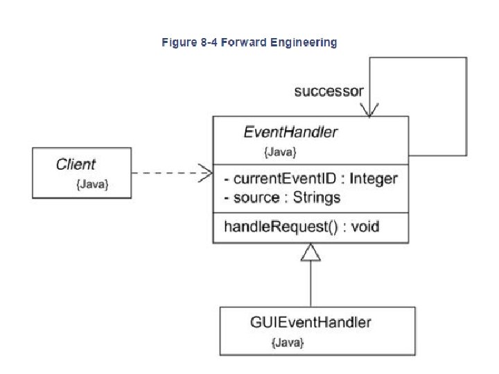
3. Forward and Reverse Engineering • Forward engineering is the process of transforming a model into • 1. 2. 3. 4. code through a mapping to an implementation language To forward engineer a class diagram: Identify the rules for mapping to your implementation language or languages of choice. Depending on the semantics of the languages you choose, you may have to constrain your use of certain UML features. For example, the UML permits you to model multiple inheritance, but Smalltalk permits only single inheritance. Use tagged values to specify your target language. Use tools to forward engineer your models.
• Reverse engineering - It is the process of transforming code into a model through a mapping from a specific implementation language - To reverse engineer a class diagram: 1. Identify the rules for mapping from your implementation language or languages of choice 2. Using a tool, point to the code you'd like to reverse engineer. Use your tool to generate a new model or modify an existing one that was previously forward engineered. 3. Using your tool, create a class diagram by querying the model
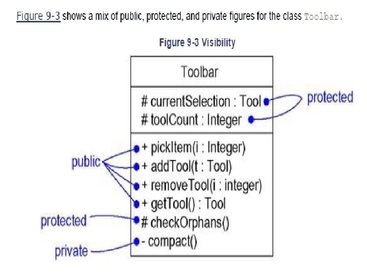
§ Visibility • One of the most important details you can specify for a classifier's attributes and operations is its visibility. • The visibility of a feature specifies whether it can be used by other classifiers. • In the UML, you can specify any of three levels of visibility.
• class may have no children. Such an element is called a leaf class and is specified in the UML by writing the property leaf below the class's name. For example, in the figure, OKButton is a leaf class, so it may have no children. • class may have no parents. Such an element is called a root class, and is specified in the UML by writing the property root below the class's name. For example, in the figure, Icon is a root class • you specify an abstract operation by writing its name in italics, just as you do for a class. By contrast, Icon: : get. ID() is a leaf operation, so designated by the property leaf. This means that the operation is not polymorphic and may not be overridden.
§ Multiplicity • The number of instances a class may have is called its multiplicity. • Multiplicity is a specification of the range of allowable cardinalities an entity may assume. • In the UML, you can specify the multiplicity of a class by writing a multiplicity expression in the upper-right corner of the class icon. • For example, in Figure , Network. Controller is a singleton class. Similarly, there are exactly three instances of the class Control. Rod in the system.
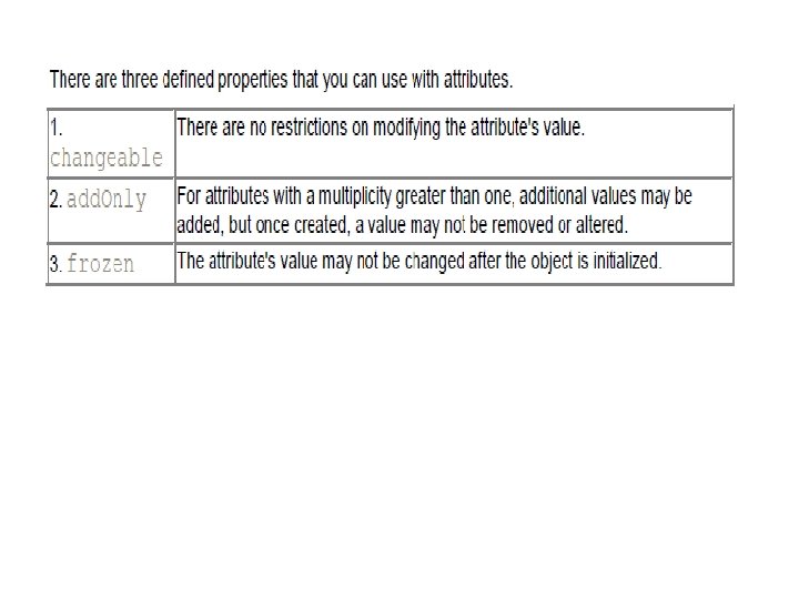
§ Attributes • you can specify the visibility, scope, and multiplicity of each attribute. • can also specify the type, initial value, and changeability of each attribute. • the syntax of an attribute in the UML is [visibility] name [multiplicity] [: type] [= initial-value] [{property-string}]
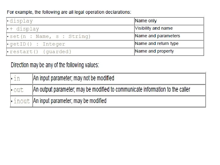
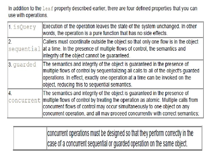
§ Operations • when you model a class's behavioral features (that is, its operations and its signals), you will simply write each operation's name. • you can also specify the visibility and scope of each operation. • You can also specify the parameters, return type, concurrency semantics, and other properties of each operation. • Collectively, the name of an operation plus its parameters (including its return type, if any) is called the operation's signature • the syntax of an operation in the UML is [visibility] name [(parameter-list)] [: return-type] [{property-string}]
Interfaces, Types, and Roles § Names • Every interface must have a name that distinguishes it from other interfaces. • A name is a textual string. That name alone is known as a simple name • a path name is the interface name prefixed by the name of the package in which that interface lives
§ Operations - interface is a named collection of operations used to specify a service of a class or of a component - Operations may be drawn showing only their name, or they may be augmented to show their full signature and other properties, as in Figure above
§ Relationships • Like a class, an interface may participate in generalization, association, and dependency relationships. • In addition, an interface may participate in realization relationships. • Realization is a semantic relationship between two classifiers in which one classifier specifies a contract that another classifier guarantees to carry out. • interface specifies a contract for a class or a component without dictating its implementation • it commits to carry out all these contracts faithfully, which means that it provides a set of methods that properly implement the operations defined in the interface.
• • We use the simple form in which the interface and its realization relationship are rendered as a lollipop sticking off to one side of a class or component limitation of this style is that you can't directly visualize the operations or signals provided by the interface Second, you can use the expanded form in which you render an interface as a stereotyped class, which allows you to visualize its operations and other properties, and then draw a realization relationship from the classifier or component to the interface In the UML, a realization relationship is rendered as a dashed directed line with a large open arrowhead pointing to the interface
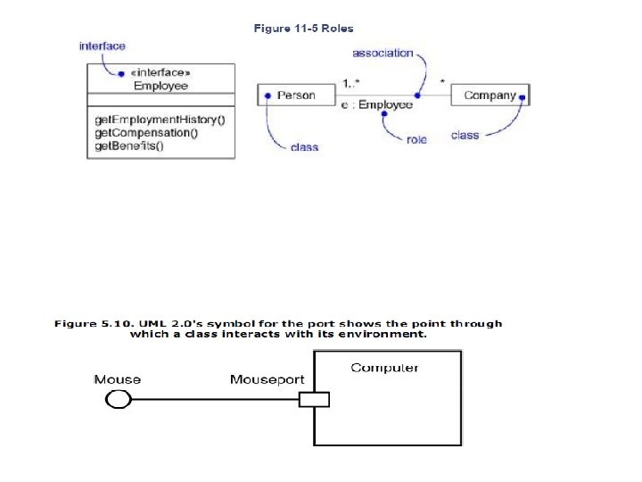
§ Types and Roles • A class may realize many interfaces. An instance of that class must therefore support all those interfaces, because an interface defines a contract, and any abstraction that conforms to that interface must, by definition, faithfully carry out that contract • each interface represents a role that the object plays. A role names a behavior of an entity participating in a particular context • In the UML, you can specify a role an abstraction presents to another abstraction by adorning the name of an association end with a specific interface • In the UML example the Person presents the role of Employee to the Company, and in that context, only the properties specified by Employee are visible and relevant to the Company.
Templates Classes • A template is a parameterized element. you can write template classes, each of which defines a family of classes • template includes slots for classes, objects, and values, and these slots serve as the template's parameters. • You can't use a template directly; you have to instantiate it first. Instantiation involves binding these formal template parameters to actual ones. • most common use of template classes is to specify containers that can be instantiated for specific elements, making them type-safe
• For example, the following C++ code fragment declares a parameterized Map class. template<class Item, class Value, int Buckets> class Map { public: virtual Boolean bind(const Item&, const Value&); virtual Boolean is. Bound(const Item&) const; . . . }; You might then instantiate this template to map Customer objects to Order objects. m : Map<Customer, Order, 3>; • Denote a template class just as you do an ordinary class, but with an additional dashed box in the upperright corner of the class icon, which lists the template parameters.
• you can model the instantiation of a template class in two ways. • First, you can do so implicitly, by declaring a class whose name provides the binding. • Second, you can do so explicitly, by using a dependency stereotyped as bind, which specifies that the source instantiates the target template using the actual parameters.
§ Standard Elements • All of the UML's extensibility mechanisms apply to classes. • We can use tagged values to extend class properties (such as specifying the version of a class) and stereotypes to specify new kinds of components
Active Objects
Advanced Relationships § Dependency • dependency is a using relationship, specifying that a change in the specification of one thing (for example, class Set. Top. Controller) may affect another thing that uses it (for example, class Channel. Iterator), but not necessarily the reverse
• Graphically, a dependency is rendered as a dashed line, directed to the thing that is depended on. • Apply dependencies when you want to show one thing using another. • there are eight stereotypes that apply to dependency relationships among classes and objects in class diagrams.
• there are two stereotypes that apply to dependency relationships among packages. • Two stereotypes apply to dependency relationships among use cases: • three stereotypes when modeling interactions among objects.
• One stereotype you'll encounter in the context of state machines is • one stereotype that you'll encounter in the context of organizing the elements of your system into subsystems and models is § Generalization • generalization is a relationship between a general thing (called the superclass or parent) and a more specific kind of that thing (called the subclass or child).
• UML defines one stereotype and four constraints that may be applied to generalization relationships - there is the one stereotype. - there are four standard constraints that apply to generalization relationships.
§ Association • association is a structural relationship, specifying that objects of one thing are connected to objects of another. • For example, a Library class might have a one-to-many association to a Book class, indicating that each Book instance is owned by one Library instance • four basic adornments that apply to an association: a name, the role at each end of the association, the multiplicity at each end of the association, and aggregation 1. Navigation • it's possible to navigate from objects of one kind to objects of the other kind. Unless otherwise specified, navigation across an association is bidirectional. • there are some circumstances in which you'll want to limit navigation to just one direction
2. Visibility • association between two classes, objects of one class can see and navigate to objects of the other • limit the visibility across that association relative to objects outside the association.
• For example, as Figure shows, there is an association between User. Group and User and another between User and Password. Given a User object, it's possible to identify its corresponding Password objects. However, a Password is private to a User, so it shouldn't be accessible from the outside • you can navigate to its User objects (and vice versa), but you cannot in turn see the User object's Password objects; they are private to the User. • Private visibility indicates that objects at that end are not accessible to any objects outside the association; protected visibility indicates that objects at that end are not accessible to any objects outside the association, except for children of the other end.
3. Qualification • It is an association attribute whose values partition the set of objects related to an object across an association. • You render a qualifier as a small rectangle attached to the end of an association, placing the attributes in the rectangle, as the figure shows
4. Interface Specifier • interface is a collection of operations that are used to specify a service of a class or a component; every class may realize many interfaces. • For example, in the vocabulary of a human resources system, a Person class may realize many interfaces: IManager, IEmployee, Iofficer • As Figure shows, you can model the relationship between a supervisor and her workers with a one-to-many
5. Composition • Composition is a form of aggregation, with strong ownership and coincident lifetime as part of the whole • object may be a part of only one composite at a time. For example, in a windowing system, a Frame belongs to exactly one Window • composite must manage the creation and destruction of its parts
6. Association Classes • In an association between two classes, the association itself might have properties. • For example, in an employer/employee relationship between a Company and a Person, there is a Job that represents the properties of that relationship that apply to exactly one pairing of the Person and Company. • modeling element that has both association and class properties. • render an association class as a class symbol attached by a dashed line to an association as in Figure
7. Constraints • UML defines five constraints that may be applied to association relationships. • First, you can distinguish if the association is real or conceptual. • there is one constraint for managing related sets of associations:
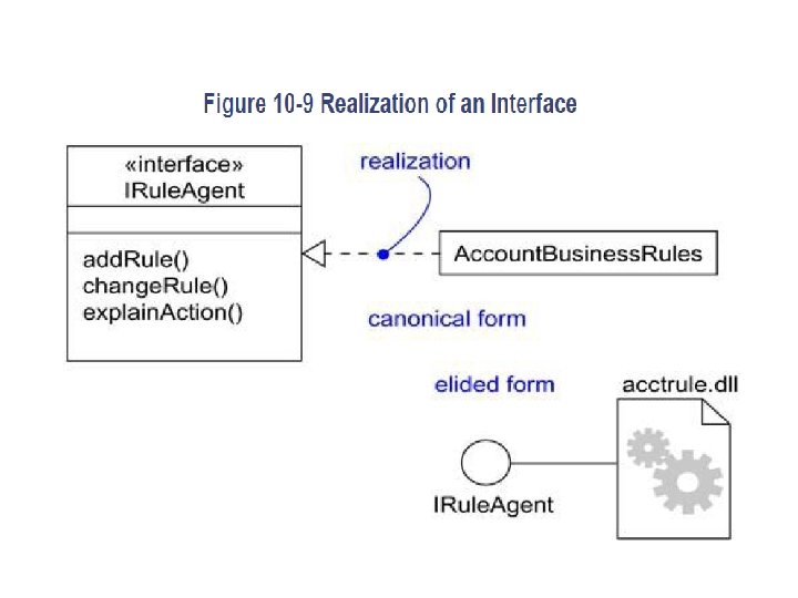
8. Realization • A realization is a semantic relationship between classifiers in which one classifier specifies a contract that another classifier guarantees to carry out. • Graphically, a realization is rendered as a dashed directed line with a large open arrowhead pointing to the classifier that specifies the contract. • its notation is a combination of the notation for dependency and generalization. • You'll use realization in two circumstances: in the context of interfaces and in the context of collaborations. • you can represent realization in two ways: in the canonical form (using the interface stereotype and the dashed directed line with a large open arrowhead) and in an elided form (using the interface lollipop notation).
Composite structure diagrams • It is diagram that shows internal structure of a classifier, including its interaction points to other parts of system • it shows configuration & relationship of parts that together perform behavior of containing classifier • It include part, port, connector, interfces, delegate § Part: - Part is element that represent a set of one or more instance which are owned by a containing classifier instances - Part shown as rectangle containing within the body of a class or component element § Port: - It is externally visible part of containing classifier Define interaction between classifier & environment A port is a way to offer functionality from a composite structure without exposing the internal details of how that functionality is realized.
- Appear on boundary of contained part, class or composite structure § interface - interface is a collection of operations that specify a service of a class or component.
2. 1. Required and provided interfaces • Required interfaces show what the owning classifier may ask of its environment through a given port. • Provided interfaces show what functionality a classifier exposes to the environment.
- Provided interface is shown as a “ball on a stick” attached to a edge of classifier element - Required interface is shown as a “cup on a stick” § Delegates - Delegate connector is used for defining internal working of a component’s external part & interfaces - Shown as arrow with a << delegate >> stereotype
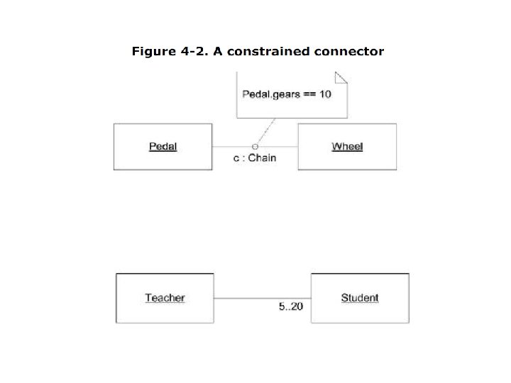
§ Connectors represent communication links between instances of classes participating in an internal structure. You can provide name and type information for a connector using the following format: name: classname where: • name= Is the name of the connector. The name can be used later in collaborations to reference this connector. • Classname= Is the name of an association this connector represents. • Figure 4 -1. The link between a Pedal and a Wheel is a connector named "c, " which is a Chain
2. 2. Realizing port implementations • If the classifier owning the port provides the implementation of the functionality itself, the port is considered a behavioral port. • On the other hand, if the functionality is realized by internal elements, you link the connector to internal classifiers that provide the implementation. This is typically used for composite structures such as components and subsystems. • Figure 4 -7. A port linked to an internal implementation
2. 3. Multiple connectors UML 2. 0 allows you to have multiple connectors leading from a port to different internal elements.
2. 4. Port multiplicity A classifier may specify multiplicity for a port like any other element. Simply place the desired number of port instances in brackets after the port name and type (if present).
2. 5. Port typing • In practice, when a port is instantiated, it is represented by a classifier that realizes the • provided interfaces. Any communication with this interaction point simply passes the • information to internal classifiers that realize the behavior. UML 2. 0 allows you to specify the • type of a port using classes to provide more sophisticated behavior.
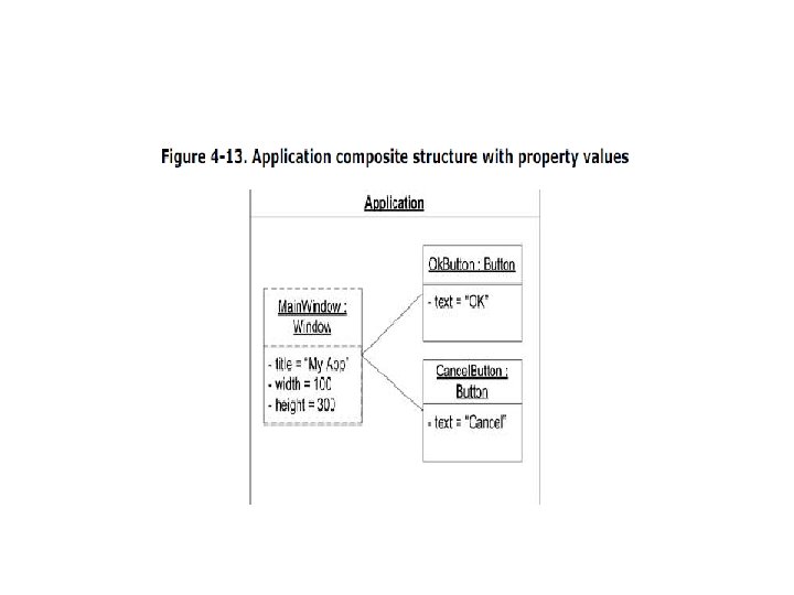
• Structured Classes and Properties • Figure 4 -12. The Application, Window, and Button relationships as a composite structure