Composite Filament Winding Machine P 09226 Detailed Design




- Slides: 21
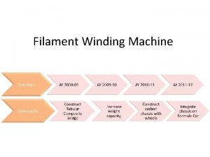
Composite Filament Winding Machine P 09226 Detailed Design Review Christofer Brayton Shijo George Alex Sandy Tiago Santos Daniel Weimann
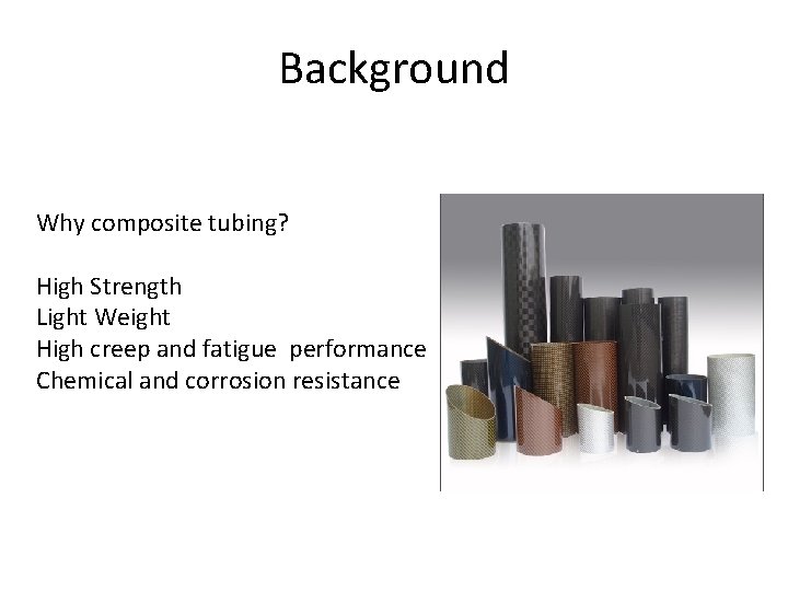
Background Why composite tubing? High Strength Light Weight High creep and fatigue performance Chemical and corrosion resistance
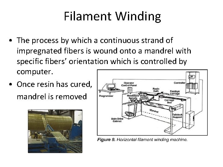
Filament Winding • The process by which a continuous strand of impregnated fibers is wound onto a mandrel with specific fibers’ orientation which is controlled by computer. • Once resin has cured, mandrel is removed
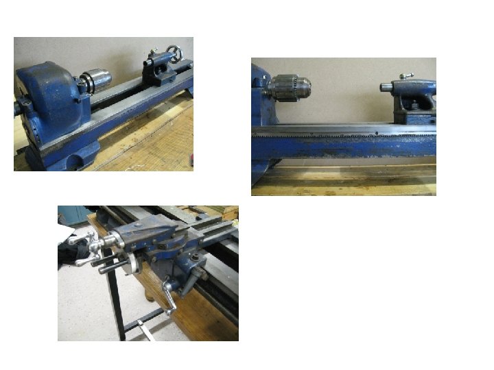
RIT First Generation Filament Winding Machine Primary Goals Capabilities • Produce tubes of limited • Learning Experience – New technology to dimensions • Simple to operate RIT and students involved – Create simple but bulletproof machine • Maintain tension every time • Limited range of orientation angles • Able to be expanded upon
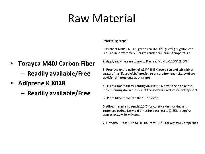
Raw Material • Torayca M 40 J Carbon Fiber – Readily available/Free • Adiprene K X 028 – Readily available/Free Processing Steps 1. Preheat ADIPRENE K 1 gallon cans to 50°C (122°F). 1 gallon can requires approximately 8 hrs to reach equilibrium temperature. 2. Apply mold release to mold. Preheat Mold to 115°C (240°F) 3. Pour the entire gallon of ADIPRENE K into a can and stir with a spatula in a “figure-eight” motion to ensure homogeneity. Add any additional ingredients at this time. 4. Fill the hot mold by pouring ADIPRENE K down the side of the mold. Pouring down the side of the mold will reduce air entrapment. 5. Place filled mold into the 115°C oven. 6. Allow material to reach 115°C for curative de-blocking and complete curing. De-mold times for small parts (0. 25 lb) require approximately 20 minutes. 7. Optional - Post Cure for 16 hours at 115°C for optimum properties
Creel
Tension
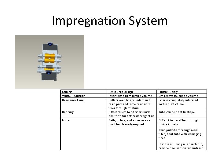
Impregnation System Criteria Waste Reduction Residence Time Bending Issues Resin Bath Design Insert plate to minimize volume Rollers keep fibers underneath resin pool and force resin onto fiber through rotation Offset rollers bend fibers back and forth for better impregnation Bath, rollers, and excess waste must be cleaned/emptied Plastic Tubing Limited waste due to volume Fiber is completely saturated within plastic tube Tube can be bent to shape Difficult to pass fiber through tubing initially Can’t pull fiber through resin filled, bent tube with damaging fiber Dispose of tubing after each run; provide new section for each run
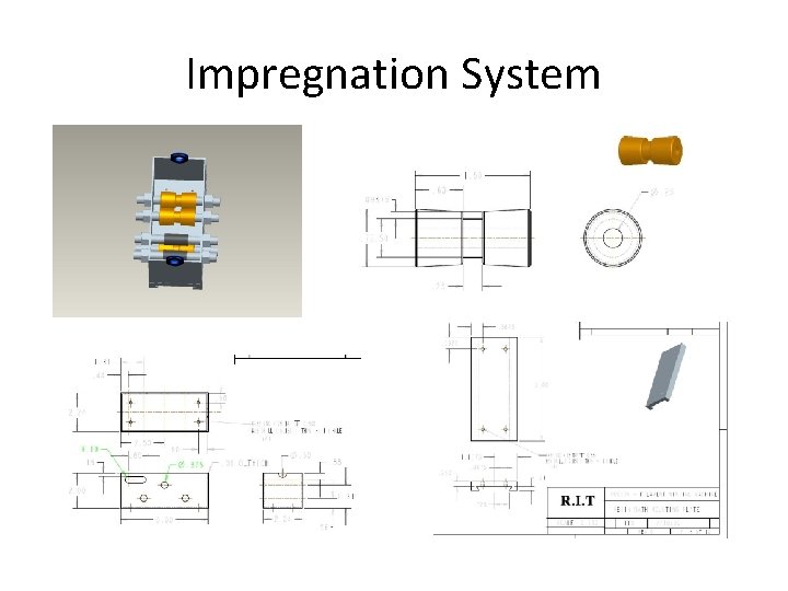
Impregnation System
Mandrel
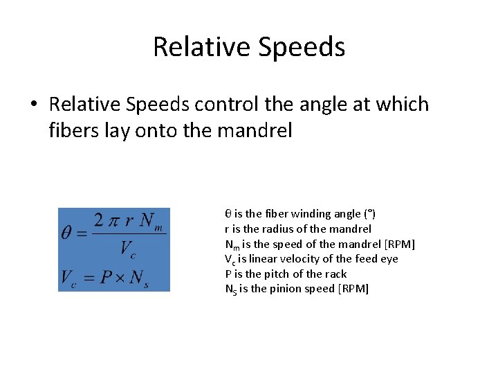
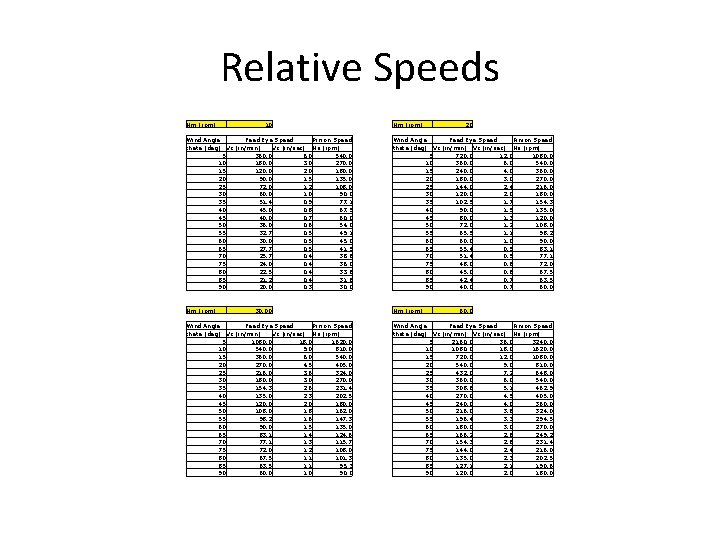
Relative Speeds • Relative Speeds control the angle at which fibers lay onto the mandrel θ is the fiber winding angle (°) r is the radius of the mandrel Nm is the speed of the mandrel [RPM] Vc is linear velocity of the feed eye P is the pitch of the rack NS is the pinion speed [RPM]
Relative Speeds Nm (rpm) 10 Nm (rpm) 20 Feed Eye Speed Wind Angle Pinion Speed theta (deg) Vc (in/min) Vc (in/sec) Ns (rpm) 5 360. 0 6. 0 540. 0 10 180. 0 3. 0 270. 0 15 120. 0 2. 0 180. 0 20 90. 0 1. 5 135. 0 25 72. 0 1. 2 108. 0 30 60. 0 1. 0 90. 0 35 51. 4 0. 9 77. 1 40 45. 0 0. 8 67. 5 45 40. 0 0. 7 60. 0 50 36. 0 0. 6 54. 0 55 32. 7 0. 5 49. 1 60 30. 0 0. 5 45. 0 65 27. 7 0. 5 41. 5 70 25. 7 0. 4 38. 6 75 24. 0 0. 4 36. 0 80 22. 5 0. 4 33. 8 85 21. 2 0. 4 31. 8 90 20. 0 0. 3 30. 0 Feed Eye Speed Wind Angle Pinion Speed theta (deg) Vc (in/min) Vc (in/sec) Ns (rpm) 5 720. 0 12. 0 1080. 0 10 360. 0 6. 0 540. 0 15 240. 0 4. 0 360. 0 20 180. 0 3. 0 270. 0 25 144. 0 2. 4 216. 0 30 120. 0 2. 0 180. 0 35 102. 9 1. 7 154. 3 40 90. 0 1. 5 135. 0 45 80. 0 1. 3 120. 0 50 72. 0 1. 2 108. 0 55 65. 5 1. 1 98. 2 60 60. 0 1. 0 90. 0 65 55. 4 0. 9 83. 1 70 51. 4 0. 9 77. 1 75 48. 0 0. 8 72. 0 80 45. 0 0. 8 67. 5 85 42. 4 0. 7 63. 5 90 40. 0 0. 7 60. 0 Nm (rpm) 30. 00 Feed Eye Speed Wind Angle Pinion Speed theta (deg) Vc (in/min) Vc (in/sec) Ns (rpm) 5 1080. 0 18. 0 1620. 0 10 540. 0 9. 0 810. 0 15 360. 0 6. 0 540. 0 20 270. 0 4. 5 405. 0 25 216. 0 3. 6 324. 0 30 180. 0 3. 0 270. 0 35 154. 3 2. 6 231. 4 40 135. 0 2. 3 202. 5 45 120. 0 2. 0 180. 0 50 108. 0 1. 8 162. 0 55 98. 2 1. 6 147. 3 60 90. 0 1. 5 135. 0 65 83. 1 1. 4 124. 6 70 77. 1 1. 3 115. 7 75 72. 0 1. 2 108. 0 80 67. 5 1. 1 101. 3 85 63. 5 1. 1 95. 3 90 60. 0 1. 0 90. 0 60. 0 Feed Eye Speed Wind Angle Pinion Speed theta (deg) Vc (in/min) Vc (in/sec) Ns (rpm) 5 2160. 0 36. 0 3240. 0 10 1080. 0 18. 0 1620. 0 15 720. 0 12. 0 1080. 0 20 540. 0 9. 0 810. 0 25 432. 0 7. 2 648. 0 30 360. 0 6. 0 540. 0 35 308. 6 5. 1 462. 9 40 270. 0 4. 5 405. 0 45 240. 0 4. 0 360. 0 50 216. 0 3. 6 324. 0 55 196. 4 3. 3 294. 5 60 180. 0 3. 0 270. 0 65 166. 2 2. 8 249. 2 70 154. 3 2. 6 231. 4 75 144. 0 2. 4 216. 0 80 135. 0 2. 3 202. 5 85 127. 1 2. 1 190. 6 90 120. 0 2. 0 180. 0
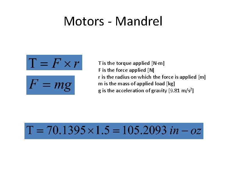
Motors - Mandrel Τ is the torque applied [N-m] F is the force applied [N] r is the radius on which the force is applied [m] m is the mass of applied load [kg] g is the acceleration of gravity [9. 81 m/s 2]
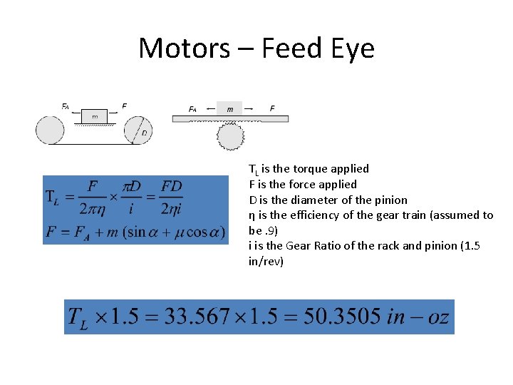
Motors – Feed Eye TL is the torque applied F is the force applied D is the diameter of the pinion η is the efficiency of the gear train (assumed to be. 9) i is the Gear Ratio of the rack and pinion (1. 5 in/rev)
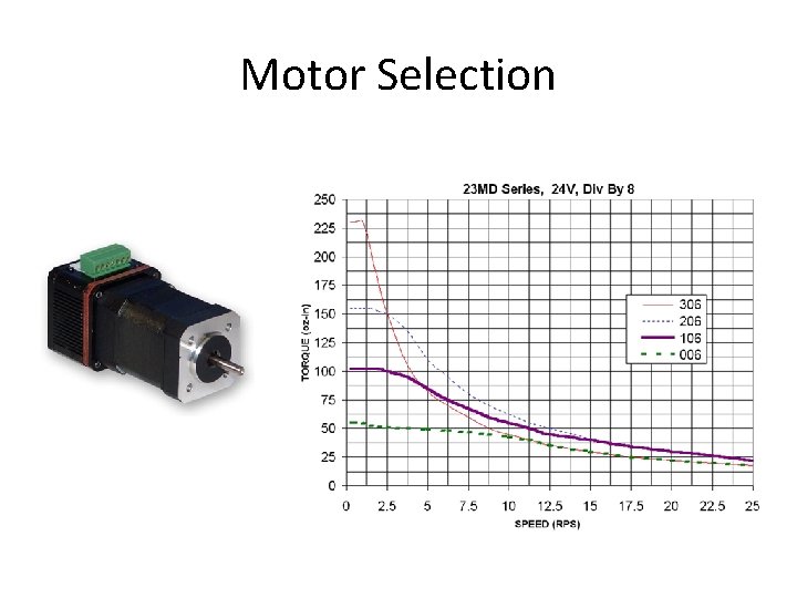
Motor Selection
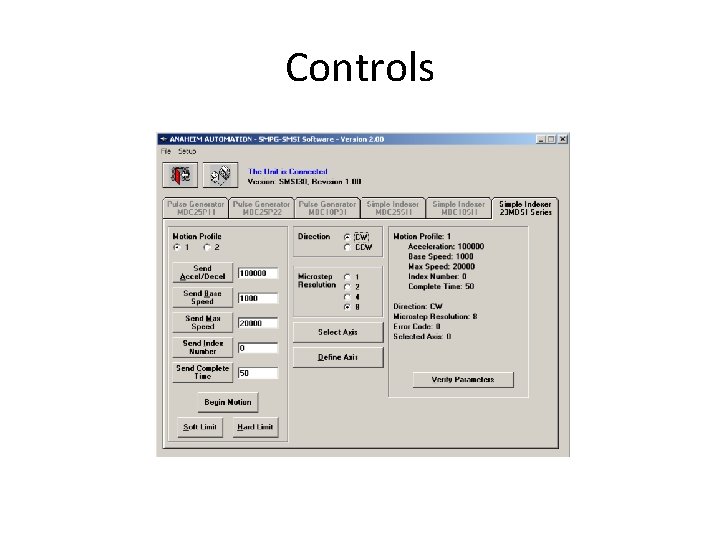
Controls
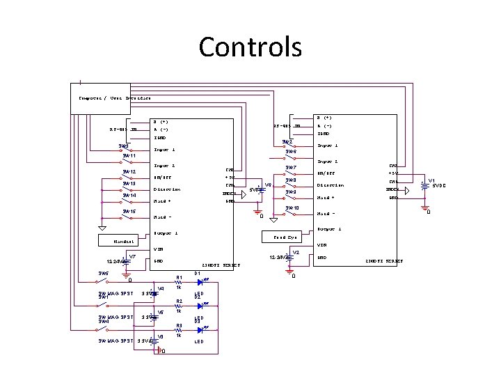
Controls Computer / User Interface B (+) RS-485 IN A (-) IGND SW 3 SW 2 Input 1 Input 2 SW 12 ON/OFF SW 13 CHB SW 7 +5 V SW 8 CHA Direction INDEX SW 14 Hard + ON/OFF 5 VDC V 6 Direction SW 9 Hard + GND CHB +5 V CHA INDEX Output 1 Feed Eye Mandrel VIN V 7 12 -24 Vdc GND SW 5 SW MAG-SPST SW 1 3. 3 Vdc SW MAG-SPST SW 4 3. 3 Vdc V 4 V 3 0 LED D 2 1 k R 3 3. 3 Vdc D 1 1 k R 2 V 5 V 2 23 MDSI SERIES R 1 0 0 Hard - LED D 3 1 k LED 0 GND V 1 5 VDC GND SW 10 SW 15 SW MAG-SPST Input 1 SW 6 SW 11 12 -24 Vdc A (-) 23 MDSI SERIES
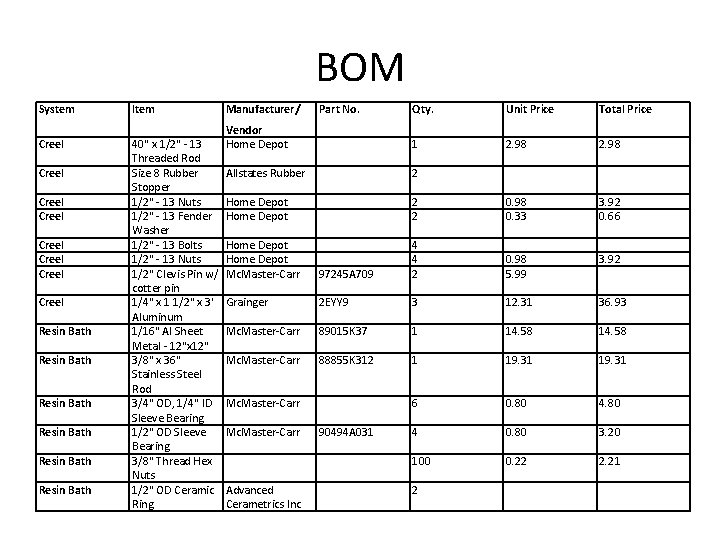
BOM System Creel Creel Resin Bath Resin Bath Item 40" x 1/2" - 13 Threaded Rod Size 8 Rubber Stopper 1/2" - 13 Nuts 1/2" - 13 Fender Washer 1/2" - 13 Bolts 1/2" - 13 Nuts 1/2" Clevis Pin w/ cotter pin 1/4" x 1 1/2" x 3' Aluminum 1/16" Al Sheet Metal - 12"x 12" 3/8" x 36" Stainless Steel Rod 3/4" OD, 1/4" ID Sleeve Bearing 1/2" OD Sleeve Bearing 3/8" Thread Hex Nuts 1/2" OD Ceramic Ring Manufacturer/ Part No. Qty. Unit Price Total Price Vendor Home Depot 1 2. 98 Allstates Rubber 2 Home Depot 2 2 0. 98 0. 33 3. 92 0. 66 Home Depot Mc. Master-Carr 97245 A 709 4 4 2 0. 98 5. 99 3. 92 Grainger 2 EYY 9 3 12. 31 36. 93 Mc. Master-Carr 89015 K 37 1 14. 58 Mc. Master-Carr 88855 K 312 1 19. 31 6 0. 80 4 0. 80 3. 20 100 0. 22 2. 21 Mc. Master-Carr Advanced Cerametrics Inc 90494 A 031 2
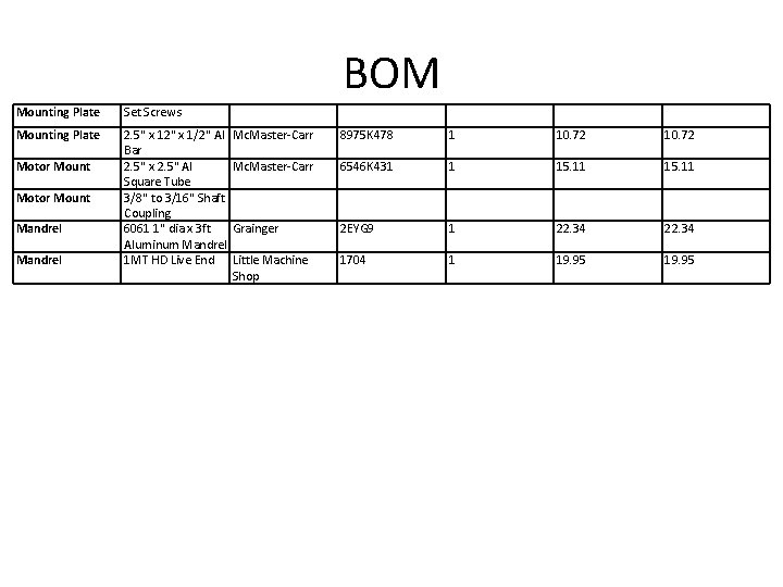
BOM Mounting Plate Set Screws Mounting Plate 2. 5" x 12" x 1/2" Al Bar 2. 5" x 2. 5" Al Square Tube 3/8" to 3/16" Shaft Coupling 6061 1" dia x 3 ft Aluminum Mandrel 1 MT HD Live End Motor Mount Mandrel Mc. Master-Carr 8975 K 478 1 10. 72 Mc. Master-Carr 6546 K 431 1 15. 11 Grainger 2 EYG 9 1 22. 34 Little Machine Shop 1704 1 19. 95
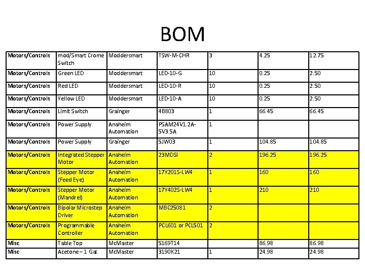
BOM Motors/Controls mod/Smart Crome Moddersmart Switch TSW-M-CHR 3 4. 25 12. 75 Motors/Controls Green LED Moddersmart LED-10 -G 10 0. 25 2. 50 Motors/Controls Red LED Moddersmart LED-10 -R 10 0. 25 2. 50 Motors/Controls Yellow LED Moddersmart LED-10 -A 10 0. 25 2. 50 Motors/Controls Limit Switch Grainger 4 B 803 1 66. 45 Motors/Controls Power Supply Anaheim Automation PSAM 24 V 1. 2 A 5 V 3. 5 A 1 Motors/Controls Power Supply Grainger 5 JW 03 1 104. 85 Motors/Controls Integrated Stepper Anaheim Motor Automation 23 MDSI 2 196. 25 Motors/Controls Stepper Motor (Feed Eye) Anaheim Automation 17 Y 201 S-LW 4 1 160 Motors/Controls Stepper Motor (Mandrel) Anaheim Automation 17 Y 402 S-LW 4 1 210 Motors/Controls Bipolar Microstep Anaheim Driver Automation MBC 25081 2 Motors/Controls Programmable Controller Anaheim Automation PCL 601 or PCL 501 2 Misc Table Top Acetone – 1 Gal. Mc. Master 5169 T 14 3190 K 21 86. 98 24. 98 1