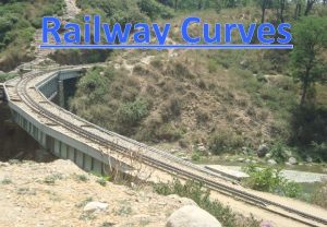
Part III Curves Concept of curve 1 1


- Slides: 48

Part – III Curves; Concept of curve 1. 1 Types of Curves, Degree of Curve, Relation between degree & Radius, curve boards & rail post Total periods - 1 1

INTRODUCTION • It is desirable to follow the straight alignment but to be changed by introduction of curve(s)for some unavoidable reasons • Connectivity to sources of traffic. • Obstructions like hills, water bodies etc. • Unstable geological formations etc. • Technical and economical considerations when river alignment, length of bridge, need for climbing steep hills. 2

• Due to the forces on a curved track, it has been estimated that the maintenance effort on curves is about 25% extra over that on a straight track. • Therefore the forces and their effect on track, vehicle and passengers are required to be systematically studied so that curves are properly designed and easily maintained. • Better understanding the vehicle movement on curves and proper laying, maintenance, realignment of curves etc track engineers will be in better position to maintain 3

Types of curves Different types of curves in the track are: • Simple curves • Compound curves • Reverse Curves 4

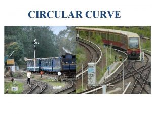
IDENTIFICATION OF CURVE • Curve is a line of which no part is straight and which changes direction without angles. • A railway curve is a track which changes alignment without any sharp corners in rails. • This change of alignment through curves is best attained through circular curve. • A circular curve has the advantage of uniform curvature means uniform change of direction. • Identification: R- radius, D- degree, direction of curve : LH/RH 5

6

7

8

9

APEX DISTANCE OPTION I (Min. Radius computed) OPTIMUM OPTION II CHOOSING APPROPRIATE CURVE 10

How does the train move on rails? • Vehicle shall be Self centering/ self stabilising • Coning is the main mechanism • SINUSOIDAL MOTION. 11

Movement of wheels on a straight track • Coning of wheels helps to keep the vehicle centrally aligned on a straight and level track also. • Slight irregularities in the track do occur as a result of moving loads and the wheels, therefore, move from side to side and the vehicles sway. Due to the coning of wheels, this side movement results in the tread circumference of one wheel increasing over the other.

Movement of wheels on a straight track • As both the wheels have to traverse the same distance, this causes one wheel to slide. Due to the resistance caused by the sliding, any further side movement is prevented. • If there was no coning, the side movement would have continued and the flange of the wheel would have come in contact with the side of the rail, causing jerks and making the ride uncomfortable. 13

Behavior of coned wheel in curved track • On Outer rails wheel has to cover great distance than inner rail • Vehicle has tendency to move sideways towards outer rail • Circumference of flange of outer wheel will be greater than that of inner wheel • Helps the outer wheel to cover longer distance than inner rail 14

15

ADVANTAGES OF CONING THE WHEELS • Helps in reducing wear & tear of the wheel flanges and rails, which is due to rubbing action of flanges with gauge face of the rail head • Provides possibility of lateral movement of the axle with its wheels • Prevent the wheels from slipping to some extent 16

Wheel set on track: play helps wheel movement σs/2 σs= Standard Play σs/2 17

Sinusoidal motion of wheel set on straight 18

Guidance of wheel on track • Straight track • Sinusoidal motion • Curved track • Shifting of center of gravity of wheel set • Actual guidance of the wheel flange by the outer rail in sharper curves • Slipping/skidding of wheels on sharp curves 19

Angularity of axle while negotiating a curve α Angle of attack 20

Curve designation • Curves are Designated By Their Radii, Except On IR & US rail roads where degree of curve is used for designation and • • • Radii For Calculation. Limiting radii (item-2 chapter I of SOD ) BG : 175 M MG : 109 M NG : 44 M 21

DEGREE OF CURVE IS THE ANGLE SUBTENDED BY 30. 5 m CHORD AT THE CENTRE 30. 5 m (100 feet ) R D R 22

RELATION BETWEEN DEGREE AND RADIUS OF THE CURVE • The value of degree can be found out, as indicated below • Angle subtended by 2 Rm Length i. e; circumference=360°. • Angle (D) subtended by 1 m Length i. e; circumference i. e D = 360° X 1 / 2 R. • Angle (D )subtended by an arc of 30. 5 m length D = 360° X 30. 5 / 2 R = 1746. 81 / R Say D = 1750 / R

Degree of Curve - Exercise Find Radius. If Degree of Curve is • 0. 50° • 2° • 4° • 5° - 3500 m 875 m 437. 5 m 350 m

CURVE MEASUREMENT: BY VERSINE (MID CHORD OFFSET ON 20 m CHORD) By Property Of Circle, V*(2 R-V) = C/2*C/2 i. e. 2 RV=C 2/4 [NEGLECTING V 2] 2 i. e. Versine, V = C /8 R V C 2 R 2 R-V R C V 25

Versine - Exercise Find Versine on 20 m Chord – If Degree of Curve is • • 0. 50° 1° 4° 5° - 14. 28 mm 28. 57 mm 114. 28 mm 142. 80 mm

PARAMETERS OF CURVES • RADIUS, R AND DEGREE OF CURVE, D • ACTUAL CANT Ca • CANT DEFICIENCY Cd • CANT EXCESS Cex • EQUILIBRIUM CANT Ce / EQUILIBRIUM SPEED Ve • RATE OF CHANGE OF ACTUAL CANT rca • RATE OF CHANGE OF CANT DEFICIENCY rcd • CANT GRADIENT, i • LENGTH OF TRANSITION, L 27

Centrifugal & Centripetal Force 28

Effects of curve: Centrifugal force • Vehicle Running at a Speed of V In a Curve of Radius R experiences Centrifugal Force = MV 2/R • UNDESIRABLE EFFECTS • Possible passenger discomfort • Possible displacement of loads • Risk of vehicle overturning 29

Effects of curve: Centrifugal force • Risk of derailment • High lateral force resulting in maintenance problems • Wear of rail & wheel flange • Lateral force on track structure 30

PART IX – CURVES Part 2 VERTICAL CURVES (TOTAL PERIODS – 05) 31

2. 1 Need for vertical curve

Vertical curves 33

Vertical Curves: Why consider Safety: a)Summit type vertical curves: The centrifugal force acts upwards. This is opposite to the weight of the vehicle and causes off-loading (reduction in wheel load) of the vehicles. The offloading of wheels if coupled with lateral forces may lead to derailment of vehicle on track. b)Sag type vertical curves: The centrifugal force acts downwards. However, if the train is on sag type vertical curve and brake is applied from locomotive, the front portion near locomotive will start decelerating, whereas the rear portion, which is on a down gradient, will continue to move forward due to the effect of gravity. In such a case, the vehicles may bunch together and if the vehicles on the sag are empty, these may get lifted up, causing off-loading. In this case, the vehicles may be prone to derailment.

Vertical Curves: Why consider

Vertical Curves 36

Need of a Vertical Curve • Vertical curves are required to be provided only where the difference in the gradients meeting is large and the forces generated may lead to unsafe conditions / discomfort. • The vertical curves provided on IR are circular. • In vertical curves, there is no requirement of transitions, since there is no super elevation and also since the forces generated are small due to the very large radii of the vertical curves. 37

VERTICAL CURVES • Vertical Curves Are Provided At Those Locations Where Algebraic Difference Between The Grades Is Equal To Or More Than 0. 4% (4 mm/m) ROUTE A B C, D, E &MG MIN. RADIUS (m) 4000 3000 2500 38

Vertical Curves • Summit type vertical curves • Sag type vertical curves 39

Vertical Curves • Important issues • Vertical acceleration • Drainage • Visibility • Shall be as flat as possible • Not allowed in • points and crossing • unballasted deck girder bridges • transition portion of horizontal curves • Summit type curves can be provided only in formation 40

PROBLEM 41

SOLUTION 42

SOLUTION 43

SOLUTION 44

SOLUTION 45

Working example • Instructor to give one example and ask the trainees to solve in class • 2 periods.

CURVE BOARD & INDICATION Indicators/Boards Provided in Curves: (1) Curve Board–Each approach of a curve should be provided with a curve board at the tangent point fixed on the outside of the curve. This Board should indicate the radius of the curve, the length of the curve, length of transition in metres and the maximum cant provided on the circular portion of curve in millimetres. (2) Rail Posts Indicating Tangent Points– On the inside of the curve, rail posts should be erected on each approach of the curve, to indicate the positions of the beginning and end of transition curves. These rail posts may be painted in red and white colours respectively. In the case of non-transitioned curve, similar rail post should be erected on the tangent track and on the circular curve over which the cant is run out, indicating the beginning and end of the virtual transition.

Thanks
 Hamlet act iii scene iii
 Va handbook 5017 part iii appendix a
 Hill equation for hemoglobin
 S curve and j curve
 Importance of balanced occlusion
 Biotic potential and environmental resistance
 This leads the balance wheel through the belt connection
 Part whole model subtraction
 Unit ratio definition
 Brainpop ratios
 Define technical description
 Front bar equipment
 The part of a shadow surrounding the darkest part
 Minitab adalah
 Ideal self is
 Contoh marketing concept
 Space curves
 Symmetrical frequency curve
 Titration curve for arginine
 Isometric drawing with curves
 Some animals are dangerous *
 How is a supersaturated solution made
 Area between two curves formula
 Redox titration definition
 Railway curves iricen
 Creating production possibilities schedules and curves
 S and j curves
 Mirror curved outward
 Glycine titration curve
 Intersection of solids examples
 Cooling curve
 Beam strength of gear tooth definition
 Rectangular hyperbola engineering drawing
 Is a cycloid a conic section
 Area of polar curves practice
 Learning curves 2003
 Highway curves banked and unbanked
 S and j curves
 Asymptote of a curve
 Strong acid titration curve
 Advantage of conductometric titration
 18curves
 Polar curve
 Widening of gauge on curves
 Drivers ed module 5 topic 1
 Physical behavior of matter heating and cooling curves
 How to read a solubility curve
 13 curves
 Uses of convex mirror


