Mulch v In agriculture and gardening mulch is


, leaves, hay,")


 is the maximum quantity of")


")

")
")


 fringe (주변 ), water")

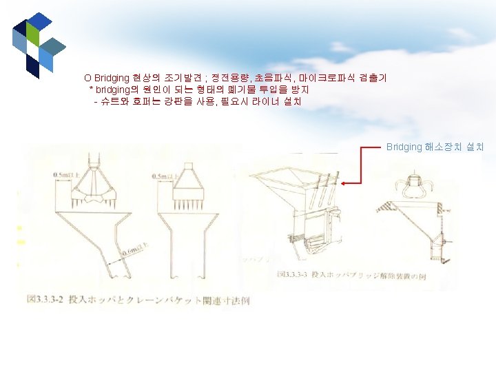
 v 그림 11 -63 일반적 인 매립지")


은 H, 7/8은 O 총 waste 250, 000 lb* 0. 02875")


 분류 WG")


 A 항목 B C")
 solid fuels with")
 • • Pollutant Uncontrolled ESPc SD/ESPd SD/FFe")

- Slides: 190
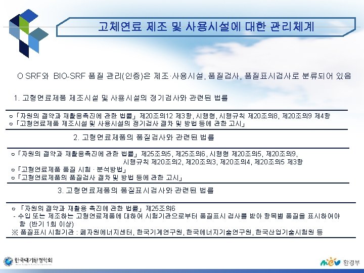
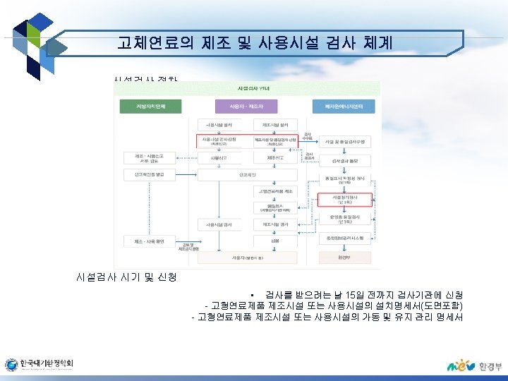
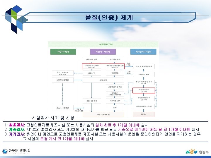
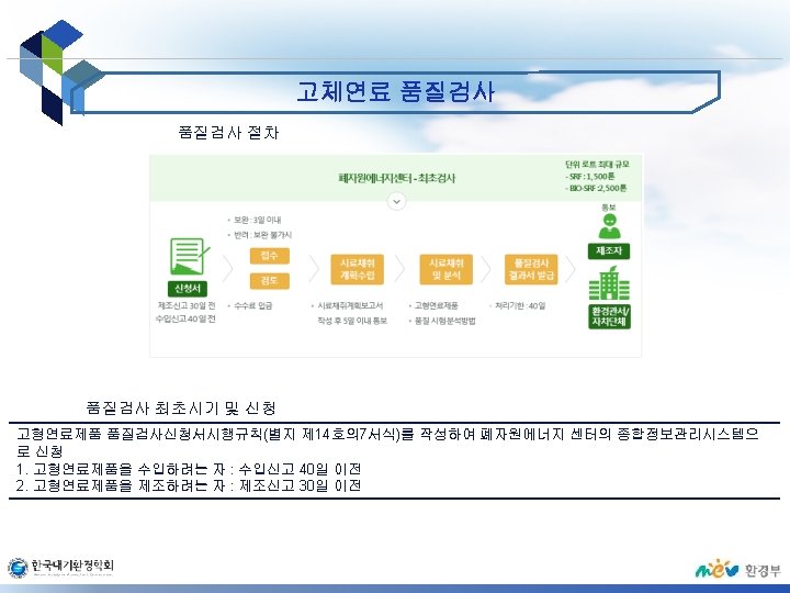
Mulch v In agriculture and gardening, mulch is a protective cover placed over the soil, primarily to modify the effects of the local climate. v A wide variety of natural and synthetic materials are used. v Mulch 사용의 장점(74 -1 -7)
Mulch: purpose v To adjust soil temperature by helping soil retain more heat in spring and fall, and by keeping soil cool and evening out temperature swings (흔들림) during hot and variable summer conditions. v To control weeds by blocking the sunlight necessary for germination (발아). v To retain water by slowing evaporation. v To add organic matter and nutrients to the soil through the gradual breakdown of the mulch material. v To repel (퇴치하다) insects. v To incrementally (점차적으로) improve growing conditions by reflecting sunlight upwards to the plants, and by providing
Mulch: variety of materials v Organic residues: grass clippings (깎아 낸 것), leaves, hay, straw (짚), shredded bark (나무 껍질), whole bark nuggets (덩어리), sawdust ( 톱밥), shells, wood chips, shredded newspaper, cardboard (골판지), wool (모직물), etc. v Compost: This relies on fully composted material, where potential weed seed has been eliminated, or else the mulch will actually produce weed cover. v Rubber mulch: Environmentally safe & secure; made from 100% recycled rubber. v Plastic mulch (비닐): Crops grow through slits (갈라진 틈) or holes in thin plastic sheeting. This method is predominant in
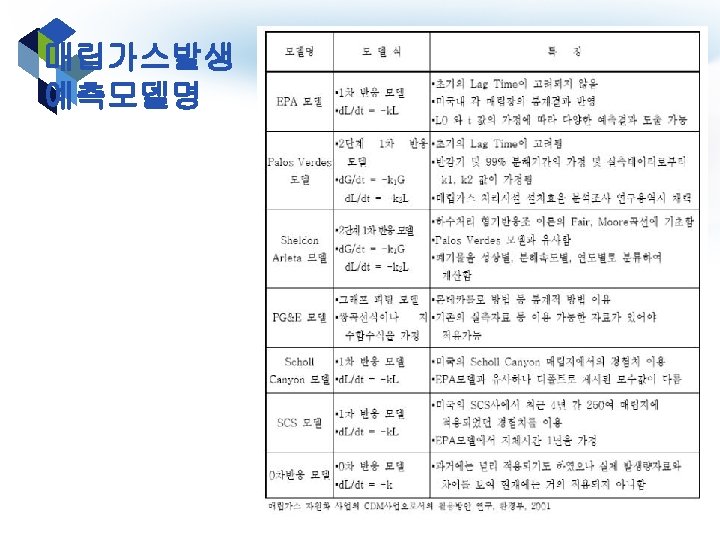
Figure 11 -12 Graphical representation of gas production over a five-year period from the rapidly and slowly decomposable organic materials placed in a landfill (p. 406) v 가스 발생에 의해 측정된 분해속도는 초기 2년내 에 최고에 달하고 25년 까지 게속되면서 천천히 줄어듬 v Triangular gas production model v (89 -3 -6) 매립가스 발 생량 예측 시 사용되는 Kinetic Model 3가지 와 그 특징을 설명하시오. v (83 -2 -1) 매립가스발생 량을 추정하는 방법에 대
Figure 11 -12 Graphical representation of gas production over a five-year period from the rapidly and slowly decomposable organic materials placed in a landfill (p. 406) v 가스 발생에 의해 측정된 분해속도는 초기 2년내 에 최고에 달하고 25년 까지 게속되면서 천천히 줄어듬 v Triangular gas production model v (89 -3 -6) 매립가스 발 생량 예측 시 사용되는 Kinetic Model 3가지 와 그 특징을 설명하시오. v (83 -2 -1) 매립가스발생 량을 추정하는 방법에 대
Figure 11 -13 Effect of reduced moisture content on the production of landfill gas (p. 407) v 매립지 수분이 제한될 때 가스발생곡선이 더 완만해 지고 가스발생이 오래 지속됨 v Bioreactor landfill과 연관지어 설명
Darcy's law v Permeability is part of the proportionality constant in Darcy's law which relates discharge (flow rate) and fluid physical properties (e. g. viscosity), to a pressure gradient applied to the porous media.
Landfill Gas Flare
LFG recovery system
Potential Exposure Pathways to Landfill Gas
Landfill gas collection and utilization in a Vancouver landfill
Modern landfill
Cation-exchange capacity v In soil science, cation-exchange capacity (CEC) is the maximum quantity of total cations, of any class, that a soil is capable of holding, at a given p. H value, for exchanging with the soil solution. v CEC is used as a measure of fertility, nutrient retention capacity, and the capacity to protect groundwater from cation contamination. v It is expressed as milliequivalent of hydrogen per 100 g (meq+/100 g), or the SI unit centi-mol per kg (cmol+/kg). v Clay and humus have electrostatic surface charges that attract the solution
Cation exchange capacity
Structure of a Landfill
Municipal waste landfill liner system
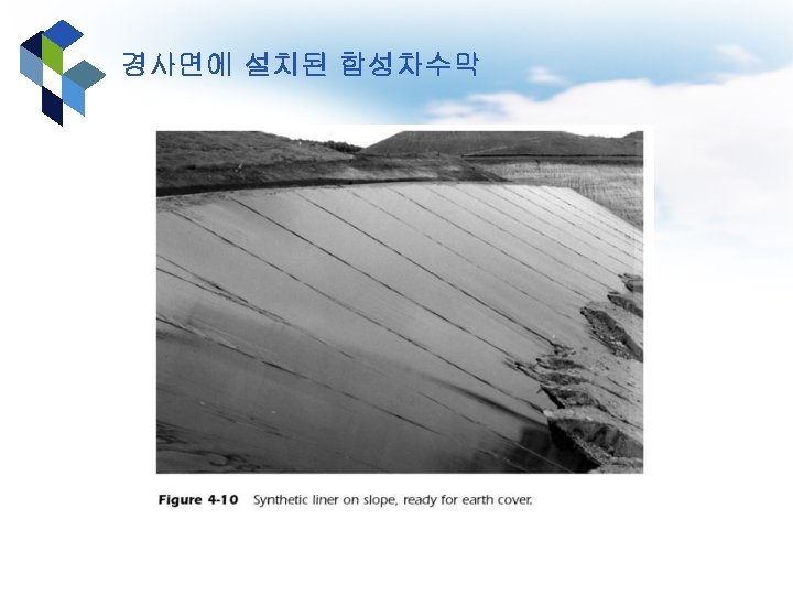
Properly installed geomembranes in a composite liner system for a municipal waste landfill
A landfill cell showing a rubberised liner is in place on the left (Hawaii)
Aerial view liner placement
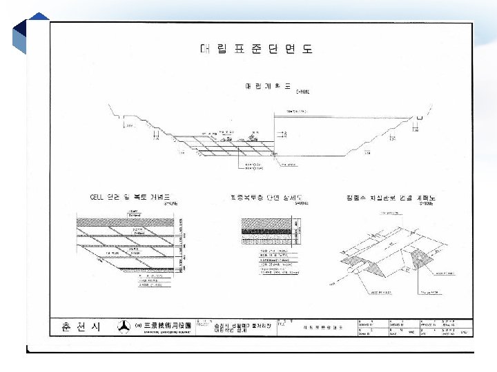
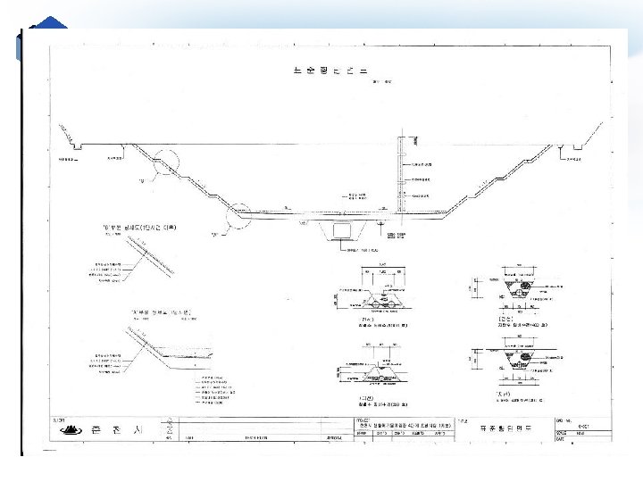
그림 11 -52 Layers of a landfill liner (p. 466)
Figure 11 -58 Classification of subsurface water (p. 476)
Vadose zone v The vadose zone, also termed the unsaturated zone, is the portion of Earth between the land surface and the phreatic ((샘과 물이 솟아나오는 지층이나 암층) zone or zone of saturation ("vadose" is Latin for "shallow (얕은)"). v It extends from the top of the ground surface to the water table (지하수면). v Water in the vadose zone has a pressure head less than atmospheric pressure, and is retained by a combination of adhesion (funiculary groundwater, 부착), and capillary action (capillary groundwater).
Vadose zone v Movement of water within the vadose zone is studied within soil physics and hydrology, particularly hydrogeology, and is of importance to agriculture, contaminant transport, and flood control. v The Richards equation is often used to mathematically describe the flow of water, which is based partially on Darcy's law. v Recharge, which is an important process that refills aquifers (대수층(帶水層)(지하수 를 품은 다공질(多孔質)의 지층)), generally occurs through the vadose zone from precipitation.
Cross-section of a hillslope depicting the vadose zone, capillary (모세관의) fringe (주변 ), water table, and phreatic or saturated zone.
Zones of subsurface water
1. Layout of landfill sites (p. 482) v 그림 11 -63 일반적 인 매립지 배치도(p. 483)
Landfill compactor
혈동리매립지-landfill compactor
Table 11 -27 Important factors that must be considered in the operation of landfills (p. 498)
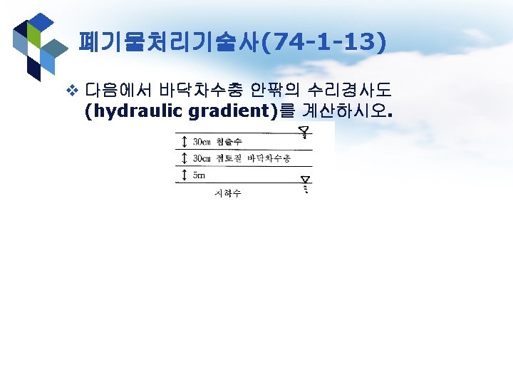
Hydraulic gradient v Definition: The hydraulic gradient is a vector gradient between two or more hydraulic head measurements over the length of the flow path. v It is also called the Darcy slope, since it determines the quantity of a Darcy flux, or discharge. A dimensionless hydraulic gradient can be calculated between two piezometers as: v Where, i: hydraulic gradient dh: difference between two hydraulic heads (Length, usually in m)
Hydraulic gradient
Slope of a road or railway v There are two common ways to describe how steep a road or railroad is. v One is by the angle in degrees, and the other is by the slope in a percentage. v The formulae for converting a slope as a percentage into an angle in degrees and vice versa are: angle = arctan * slope/100 slope = 100 tan(angle) where angle is in degrees and the trigonometry functions operate in degrees. For example, a 100% or 1000‰ slope is 45°. v A third way is to give one unit of rise in
Slope warning sign in the Netherlands
A 1371 -meter distance of a railroad with a 20‰ slope. Czech Republic
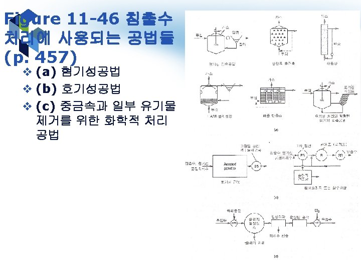
Commonly used landfilling methods
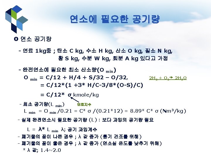
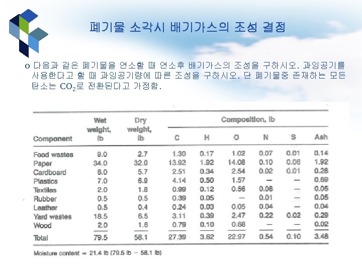
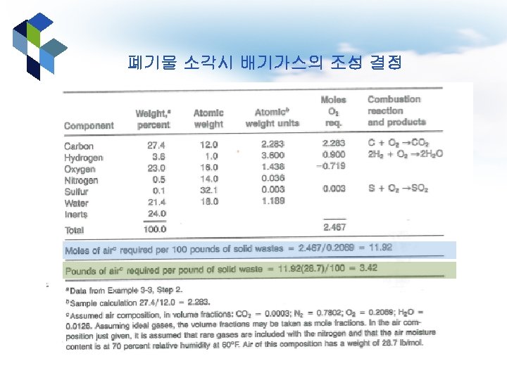
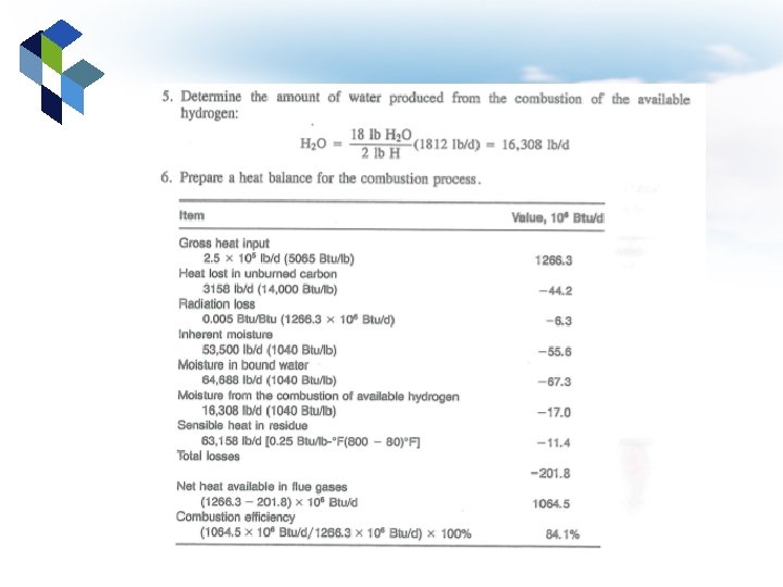
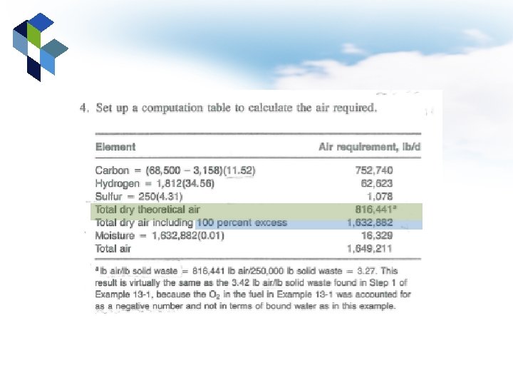
2 H 2 + O 2 2 H 2 O 11. 92*0. 0126 2*0. 9 21. 4/18 11. 92*0. 78
15. 6 21. 4+40* 15. 6
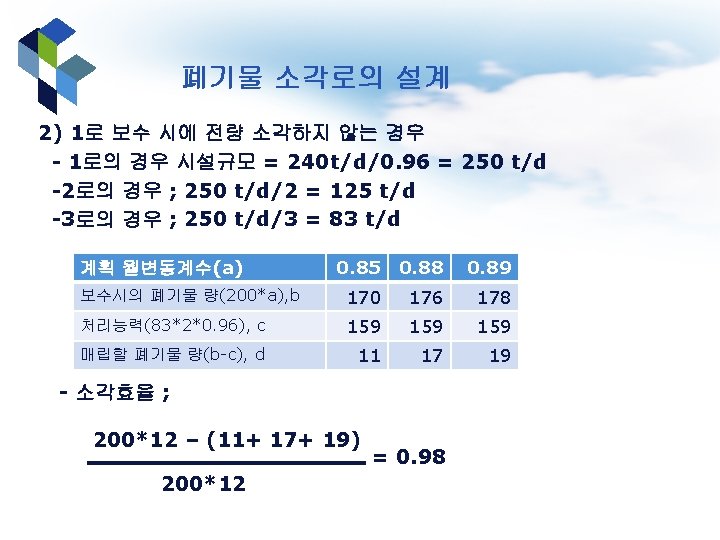
*1 t=0. 0005 lb *125 t/d*1 t/0. 0005 lb=250, 000 lb/d O 2/C=32/12, 공기중 O 2 0. 2315 가정 O 2/2 H 2=32/4, 공기중 O 2 0. 2315 가정
H 2 O중 1/8(H/O=2/16)은 H, 7/8은 O 총 waste 250, 000 lb* 0. 02875
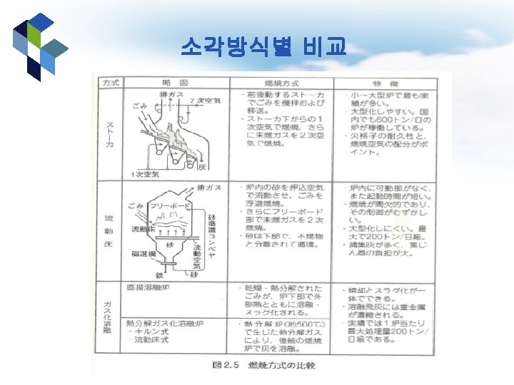
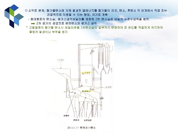
Rotary kiln 소각로
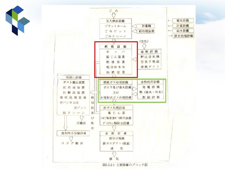
steam 2차 air 1차 air 발전기 복수기: steam condenser
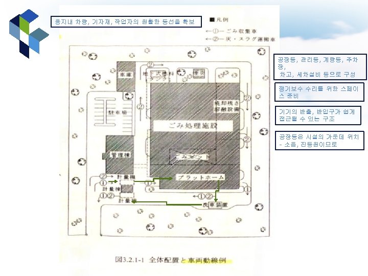
platform
대기질 개선을 위한 연료 규제정책의 도입 및 경과 o Three regulation laws for fuel are as follow; 1. extend the use of low sulfur-containing fuel ; 1981년 - designate a city to have to use low-sulfur containing fuel - firstly Seoul ; designated as a city to use low-sulfur containing fuel (below 0. 4%) in 1981, - other 20 cities ; also designated such cities (below 0. 1%) in 1994 - progressively extended to 58 cities in 2015 2. designate a city to prohibit from using solid fuel ; 1985년 - 14 cities in 1985 designated prohibit from using solid fuel as heating fuel in the residence area - extended to 20 cities in 1999 3. designate a city only to use clean fuel ; 1988년 - only use clean energy (liquid and gas fuel) designated at Seoul in 1988 - extended to 38 cities in 2002
유럽의 고형연료 품질기준 분석방법 CEN/TC 343 Solid Recovered Fuels(ICS 75. 160. 10) 분류 WG 1 WG 2 WG 3 제목 전문 용어 및 품질보 증 연료 종류 및 등급 샘플링 및 샘플 정리 및 추가적 실험방법 항목 CEN/TS 15357: 2006 CEN/TS 15358: 2006 CEN/TS 15359: 2006 CEN/TR 15508: 2006 CEN/TS 15440: 2006 CEN/TR 14980: 2004 CEN/TS 15442: 2006 CEN/TS 15443: 2006 CEN/TR 15591: 2007 CEN/TS 15747: 2008 CEN/TS 15400: 2006 WG 4 물리적 및 기계적 실 험 화학적 실험 CEN/TS 15590: 2007 CEN/TS 15401: 2010 CEN/TS 15402: 2006 CEN/TS 15404: 2006 CEN/TS 15405: 2006 CEN/TS 15414 -1: 2010 CEN/TS 15414 -2: 2010 CEN/TS 15415: 2006 CEN/TR 15716: 2008 CEN/TS 15407: 2006 CEN/TS 15408: 2006 CEN/TS 15410: 2006 CEN/TS 15411: 2006 CEN/TS 15412: 2010 CEN/TS 15413: 2006 CEN/TS 15406: 2006 CEN/TS 15414 -3: 2010 CEN/TS 15639: 2007 WG 5 CEN/TR 15441: 2006
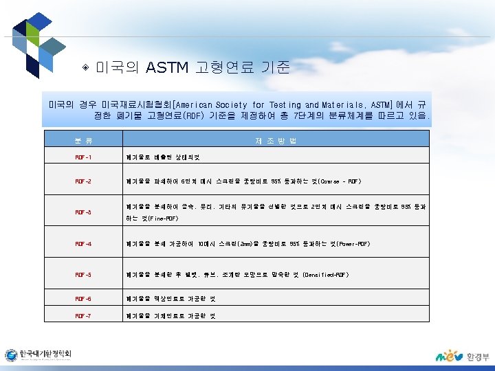
유럽의 고형연료 품질기준 분석방법 CEN/TS 343 WG 1 CEN/TS 15357: 2006 SRF- 전문용어 정의 및 설명 CEN/TS 15358: 2006 SRF-품질관리 시스템: SRF의 생산성에 적용하기 위한 특정 필수조건 CEN/TS 343 WG 2 CEN/TS 15359: 2006 SRF - 종류 및 등급 CEN/TR 15508: 2006 SRF - 분류 시스템을 입증하기 위해 사용된 SRF의 중요 특성 CEN/TS 343 WG 3 CEN/TS 15440: 2006 SRF - biomass 측정 방법 CEN/TR 15441: 2006 SRF - 직업과 관련된 건강적인 측면에서의 가이드라인 CEN/TS 343 WG 4 C EN/TS 15400: 2006 SRF - 발열량 측정방법 CEN/TS 15405: 2006 SRF - 펠렛과 연탄의 밀도 측정방법 CEN/TR 15716: 2008 SRF - 연소 거동 측정 CEN/TS 15639: 2007 SRF - 펠렛의 기계적 내구성 측정 방법 CEN/TS 343 WG 5 CEN/TS 15407: 2006 SRF - C, H, N 측정방법 CEN/TS 15408: 2006 SRF - S, Cl, F, Br 측정방법 CEN/TS 15410: 2006 SRF - 주요원소 측정 방법(Al, Ca, Fe, K, Mg, Na, P, Si, Ti) CEN/TS 15411: 2006 SRF - 미량원소 측정 방법 (As, Ba, Be, Cd, Co, Cr, Cu, Hg, Mo, Mn Ni, Pb, Se, Te, V, Zn) CEN/TS 15412: 2010 SRF - 금속 알루미늄 측정 방법 CEN/TS 15413: 2006 SRF - 실험용 시료에 의한 실험 샘플 전처리 방법
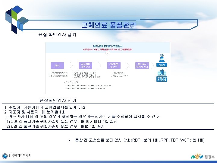
고형연료 사용시설에서의 대기오염물질 배출조사 결과 O 고형연료 사용시설에서의 대기오염물질 배출특성 실측결과 (국립환경과학원 - 2011년 실측자료) 가스상 물질 분석결과 A(SRF-RPF) 항목 B(SRF-RPF) C(SRF-RPF) D(Bio-SRF-WCF) E(혼소 : RPF, RDF, WCF) 배출허용기준 전단 CO(ppm) 200(12) NOx(ppm) 100(12) SOx(ppm) 50(12) HCl(ppm) 20(12) 후단 전단 후단 42. 1 49. 5 106. 6 87. 3 651. 3 270. 9 79. 3 38. 5 38. 3 34. 7 (9. 9∼ 55. 2) (22. 7∼ 108. 6) (45. 0∼ 200. 6) (3. 5∼ 146. 3) (225. 7∼ 1416. 7) (12. 8∼ 1188. 2) (32. 2∼ 107. 3) (12. 9∼ 52. 2) (14. 4∼ 96. 5) (11. 1∼ 227. 8) 67. 8 78. 4 109. 6 73. 3 55. 2 52. 1 75. 2 58. 7 84. 1 39. 8 (64. 3∼ 72. 5) (37. 4∼ 90. 9) (89. 5∼ 123. 0) (13. 8∼ 88. 3) (28. 3∼ 78. 3) (13. 9∼ 71. 5) (6. 9∼ 140. 7) (12. 8∼ 125. 4) (58. 4∼ 104. 1) (24. 5∼ 45. 8) 0. 6 0. 2 0. 1 0. 4 1. 0 0. 6 25. 6 2. 7 0. 1 (0. 4∼ 0. 9) (0. 0∼ 1. 0) (0. 0∼ 0. 1) (0. 0∼ 1. 3) (0. 0∼ 2. 2) (0. 0∼ 6. 4) (7. 7∼ 52. 5) (0. 2∼ 6. 2) (0. 0∼ 0. 6) (0. 0∼ 0. 7) 6. 4 1. 3 36. 7 3. 1 74. 5 4. 9 7. 9 1. 1 10. 6 3. 7 THC 분석 결과 A 항목 배출허용기준 THC 10 ppm B C D E 전단 후단 전단 후단 92. 1 97. 1 26. 3 116. 8 13. 9 2503. 1 43. 2 277. 0 20. 4 먼지 및 중금속 분석 결과 A 항목 B C D E 배출허용기준 전단 후단 전단 후단 40(12) 454. 8 1. 5 973. 7 1. 6 995. 3 6. 9 367. 8 1. 2 1784. 6 3. 3 Cr(mg/m 3) 1 0. 12 N. D 2. 95 N. D 2. 64 0. 01 0. 27 N. D 0. 24 N. D Cd(mg/m 3) 0. 1(12) 0. 27 0. 01 2. 57 0. 31 0. 74 0. 40 0. 63 0. 22 0. 50 0. 05 Ni(mg/m 3) 0. 01 24. 37 0. 01 7. 53 0. 03 0. 34 0. 12 2. 43 N. D 0. 02 먼지(mg/m 3) 20 0. 63 Cu(mg/m 3) 10 0. 11 N. D 1. 86 0. 25 0. 41 0. 11 0. 31 0. 10 0. 36 Pb(mg/m 3) 1. 6(12) 1. 43 0. 01 37. 66 0. 22 36. 52 0. 19 1. 86 N. D 0. 84 N. D Zn(mg/m 3) 10 6. 78 0. 01 95. 68 0. 04 158. 48 0. 77 7. 30 2. 43 10. 83 0. 16 Hg(mg/m 3) 0. 1(10) 7. 37 1. 79 20. 31 4. 03 9. 62 2. 08 0. 70 0. 17 46. 40 5. 93 비소(ppb) 500(12) 12. 64 1. 95 4. 91 1. 23 5. 56 2. 40 11. 71 0. 83 2. 26 3. 79 참고 : 폐기물 고형연료 사용시설의 대기오염물질 배출저감 방안 연구(국립환경과학원_2011) • THC, Hg : 모든 사용시설에서 배출허용기준 초과 고형연료 품질 기준 강화 필요 • 방지시설 전·후 농도 차이가 크게 남 적절한 방지시설 의 설치 및 운영 필요
O 고형연료 사용시설의 대기오염물질 배출특성 실측결과 VOC 분석결과(단위 : ppb) A 항목 B C D E 전단 후단 전단 후단 Dichlorodifluoromethane 8. 70 0. 00 N. D 0. 00 712. 40 6. 00 0. 00 Dichlorotetrafluoroethane 235. 32 0. 00 N. D 0. 00 11. 12 2. 20 1, 3 -butadiene 6. 95 42. 31 0. 00 0. 15 0. 00 6. 53 6. 73 8. 67 6. 54 Bromomethane 3. 28 2. 80 3. 89 0. 14 0. 44 0. 00 2. 85 3. 05 2. 96 Chloroethane 6. 31 6. 61 0. 00 4. 37 1. 88 1. 60 6. 48 6. 65 7. 36 7. 64 Trichloromonofluoromethane 0. 00 N. D 0. 00 1. 24 1. 19 Acrylonitrile 20. 80 24. 08 6. 52 3. 97 10. 23 5. 83 7. 90 43. 50 13. 82 35. 90 1, 1 -dichloroethene 8. 09 51. 48 34. 88 36. 06 0. 35 0. 00 94. 49 6. 88 21. 30 36. 99 Methylene chloride 73. 61 88. 00 N. D 66. 49 7. 69 31. 95 35. 589 1, 1, 2, 2 -tetrachloroethane 8. 20 6. 29 N. D 0. 00 N. D 5. 56 5. 36 6. 40 6. 08 1, 1 -dichloroethane 4. 74 4. 71 0. 00 3. 14 4. 71 . 276 4. 73 cis-1, 2 -dichloroethane 210. 71 7. 22 0. 00 N. D 0. 00 16. 45 7. 21 100. 62 7. 25 Chlorofoem 37. 80 31. 88 1. 50 3. 89 0. 00 10. 35 4. 72 4. 43 20. 29 18. 13 1, 2 -dichloroethane 1. 78 N. D 0. 00 5. 36 N. D 2. 30 1, 1, 1 -trichloroethane N. D N. D 4. 17 N. D 0. 60 2. 50 Benznen 167. 58 6. 62 32. 73 95. 21 53. 82 0. 08 13. 78 6. 60 20. 59 19. 50 Carbonatetrachloride 58. 46 2. 99 5. 99 3. 41 0. 37 0. 00 4. 63 0. 75 3. 61 4. 51 1, 2 -dichloropropane 20. 07 N. D 0. 00 N. D 7. 41 N. D 3. 18 1. 48 Trichloroethylene 6. 84 N. D 0. 84 0. 00 6. 82 N. D 2. 97 cis-1, 3 -dichloropropene 8. 85 N. D N. D 6. 77 N. D trans-1, 3 -dichloropropene 5. 94 3. 89 N. D 5. 81 4. 36 3. 09 4. 70 1, 1, 2 -trichloroethane N. D 0. 00 N. D N. D Toluene 27. 19 7. 54 31. 44 16. 18 11. 53 4. 36 8. 86 8. 02 8. 28 16. 06 1, 2 -dibromoethane 5. 94 N. D N. D 1. 94 1. 46 2. 50 1. 16 Tetrachloroethylene 13. 23 4. 21 2. 40 0. 59 7. 16 5. 77 4. 21 4. 73 2. 75 6. 97 Chlorobenzene 15. 96 N. D 0. 34 0. 00 2. 93 4. 40 3. 78 4. 40 Ethylbenzene 20. 61 11. 93 0. 89 2. 16 2. 47 0. 50 11. 98 11. 91 11. 95 8. 46 p-xylene 53. 89 6. 72 0. 36 5. 32 2. 08 0. 79 6. 81 6. 69 5. 39 Styrene 7. 42 4. 95 0. 00 7. 49 7. 43 6. 99 9. 46 o-xylene 7. 65 7. 46 1. 10 2. 33 1. 09 0. 00 7. 48 7. 47 5. 33 6. 04 1 -ethyl-4 -methylbenzene 17. 60 41. 27 1. 71 4. 15 1. 92 0. 82 206. 44 12. 02 41. 78 32. 55 1, 2, 4 -trimethylbenzene 58. 01 7. 74 1. 54 2. 16 1. 42 1. 29 7. 76 7. 74 5. 66 7. 03 • 1, 3 -butadiene, benzene, Toluene과 같은 특정대기유해물질 배출 고형연료 사용시설의 HAPs 관리대책 마련필요 적정 방지장치의 설치가 필요
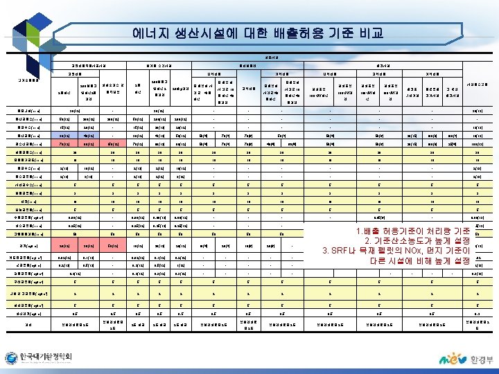
고형연료의 품질기준의 문제점 및 보완 고형연료 혼합시설에서의 대기배출허용 기준(WID ANNEX Ⅱ) solid fuels with excepiton of biomass(O 2 ontent 6%) biomass(O 2 content 6%) liquid fuels(O 2 content 3%) 구분 ∼ 50 MWTh 50∼ 100 MWTh 100∼ 300 MWTh 300∼MWTh Dust 50 50 30 30 SO 2 - 850 200 - 200 200 - 850 400∼ 200 a) 200 NOx - 400 200 - 350 300 200 - 450 200 • 혼소 비율과 관계없이 고형연료 사용시 배출허용기준 적용
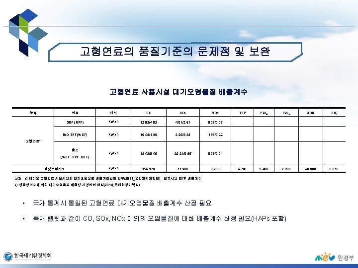
미국 고형연료의 배출계수 미국 고형연료 사용시설 배출계수(EPA-42) • • Pollutant Uncontrolled ESPc SD/ESPd SD/FFe PMf 34. 8 0. 517 4. 82× 10 -2 6. 64× 10 -2 Asg 2. 97× 10 -3 6. 70× 10 -5 5. 41× 10 -6 2. 59× 10 -6 h Cdg 4. 37× 10 -3 1. 10× 10 -4 4. 18× 10 -5 1. 66× 10 -5 h Crg 6. 99× 10 -3 2. 34× 10 -4 5. 44× 10 -5 2. 04× 10 -5 Hgg 2. 8× 10 -3 2. 10× 10 -4 1. 46× 10 -4 Nig 2. 18× 10 -3 9. 05× 10 -3 9. 64× 10 -5 3. 14× 10 -5 j Pbg 0. 1 1. 84× 10 -3 h 5. 77× 10 -4 5. 19× 10 -4 SO 2 1. 95 ND 0. 799 2. 21× 10 -1 HClg 3. 49 ND ND 2. 64× 10 -2 NOxk 2. 51 ND ND 2. 64× 10 -2 COk 0. 96 ND ND 2. 64× 10 -2 CO 2 m 1. 34× 103 ND ND 2. 64× 10 -2 CDD/CDFn 4. 73× 10 -6 8. 46× 10 -6 5. 31× 10 -8 1. 22× 10 -8 국가 통계시 통일된 고형연료 대기오염물질 배출계수 산정 필요 방지시설 유형별 배출계수 적용 대기오염물질 배출물질 파악 및 관리 가능
LOGO