The Integration of Whole Slide Imaging in the


 in Autoloader • Push “Start” bottom – – –")


- Slides: 65
The Integration of Whole Slide Imaging in the Clinical Anatomic Pathology – Limitations of Laboratory Information Systems, Image Capture Systems and Archives Yukako Yagi, Drazen Jukic, Anil Parwani, Jon Ho, William Gross, Ellen Kokal, Tony Piccoli, Michael Kistler and John Gilbertson University of Pittsburgh Medical Center (UPMC), Pittsburgh USA
Disclosure Page This work was partially supported by funding from the U. S. Air Force administered by the U. S. Army Medical Research Acquisition Activity (USAMRAA), 820 Chandler Street, Fort Detrick MD 21702 -5014, Contract No. DAMD 17 -03 -2 -0017. The content of the information does not necessarily reflect the position or policy of the U. S. Government and no official endorsement should be inferred. I (Yukako Yagi) have been Scientific Advisor for Trestle, DMetrix and Aperio.
Background The past five years has seen the emergence of whole slide imaging robots – devices that can automatically image entire microscope slides at high speed and high resolution. A typical device can capture a slide in 5 minutes at tissue sampling rates of 0. 3 -0. 5 microns/pixel, resulting in an uncompressed image file of 5 to 10 GB, and a typical pathology case contains ten slides. Though these “high resolution whole slide images” provide diagnostic information similar to that obtained by direct examination of tissue under the microscope and are proving useful in a variety of clinical activities; their novelty and sheer volume has resulted in a number of image and data management challenges. One of these challenges is that Laboratory Information Systems, which drive workflow and data management in pathology departments, are not well equipped to manage image level information.
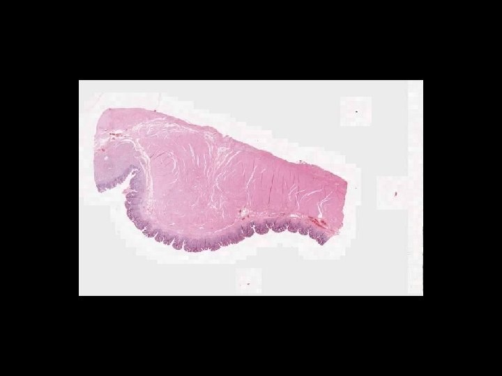
What is a whole slide image?
Microscope Imaging If we try to send all information on a glass slide, It is more than 2. 7 GB/slide. Histology slides For Static Image Telepathology, a referring pathologist has to be able to select appropriate diagnostic fields. To select suitable fields for consultation requires experience Needed virtual slide
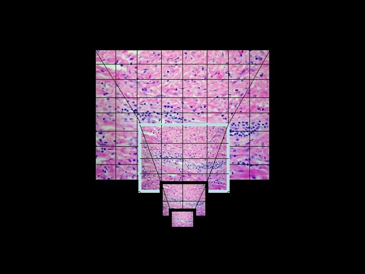
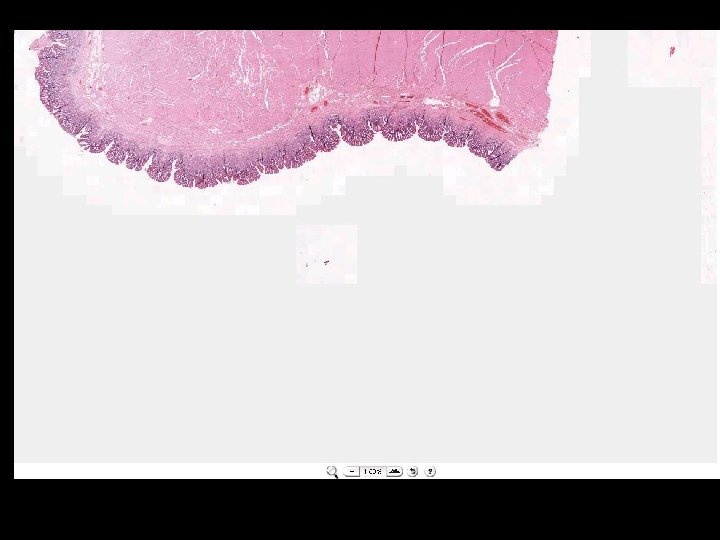
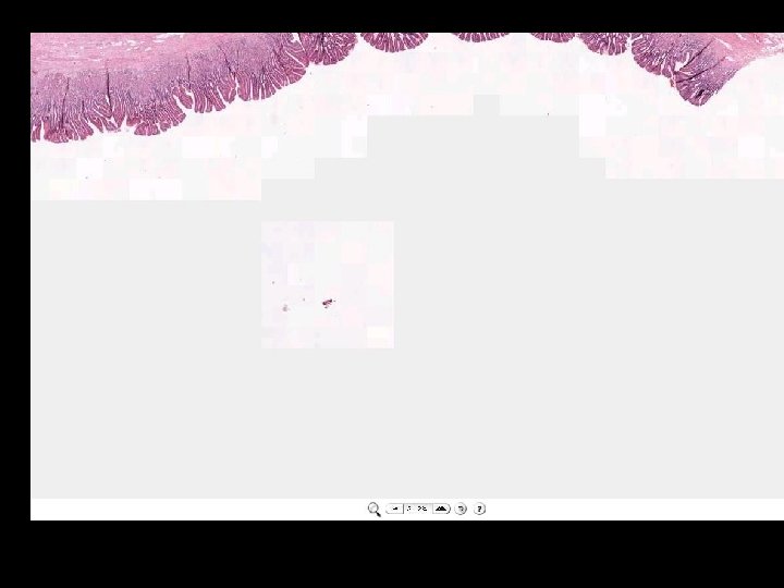
A Digital Slide • A classical whole slide image is formed by imaging a entire physical (glass) slide, field by field, and then ‘knitting” these fields together to form a seamless montage • With some display software, one can pan and zoom around the image set
Pyramid File Structure Low-magnification Mid-level magnification High-magnification
• Whole Slide Imaging A Digital Slide is a massive data set
File Size 6. 6 um CCD Section 20 x 0. 33 um • Consider a WSI system: • • • 0. 6 NA, 20 x Primary Magnification 8. 8 x 6. 6 mm CCD 6. 6 um pixels • • 0. 33 um/pixel 900 million pixels / square cm of tissue 3 bytes / pixel (24 bit color) 2. 7 GB / square centimeter of tissue per focal plane for the base image • •
Digital Slides have Issues • 2. 7 GB/cm is the base image Slide # 1 1 cm – 2. 7 + (2. 7/4) + ((2. 7/4)/4)… – 2. 7 GB x 1. 33 = 3. 5 GB per square cm of tissue • Assume 1. 5 square cm per slide, 10 slides per case: Each level is 1/2 the resolution and 1/4 the size of the one below it • • • ~ 52 GB per case! This is based on 20 x optical magnification and one focal plan 40 x magnification and 5 focal planes ~ 50 GB x 20 = 1 TB
Digital Slides have Issues • JPG 2000 compression ~ 30: 1 • ~ 115 MB per square cm per focal plane… • 1725 MB per case • UPMC 80, 000 cases/year • 138 TB per year • Is this unreasonable? • This is based on 20 x optical magnification and one focal plan
Methods: At the University of Pittsburgh, we have developed an infrastructure for the clinical use of whole slide imaging (WSI) including the implementation of different types of imaging robots, imaging quality assurance protocols, compression and storage mechanisms, mechanisms to serve whole slide images throughout the medical center, slide image viewers and a team of pathologists, imaging scientists and engineers dedicated to the evaluation of whole slide imaging systems in the clinical environment. It was quickly realized that for the clinical evaluation of WSI to be realistic, images had to be managed (or at least accounted for) within the Laboratory Information System (LIS). The team, assisted by personnel form central IT and Radiology, examined 1) The image information needs of the pathologist, histologist, imager and image data manager and how these needs can be accommodated in with the LIS and Pathology Imaging Systems and 2) Mechanisms by which specific systems – the Copath C/S Laboratory Information System, the Aperio T 2 Whole Slide Imager and UPMC’s DICOM Compliant Enterprise Image Archive - could share images and image information in support of clinical evaluations.
Why are we implementing a clinical whole slide image delivery system?
Histology Workflow From Tissue Sample to Histological Examination Surgery Center Histology Lab Biopsy Frozen Section P Tissue Sample Specimen Examination Histoprocessing Sectioning Staining P Microscopic Examination In pathology, imaging begins in histology! P Pathologist Office Microscope Slide(s) P Step that requires Pathologist
Virtual Microscopy Digital Slide Creation, Management & Analysis Surgery Center Histology Lab Biopsy Frozen Section Tissue Sample P Specimen Examination Histoprocessing Sectioning Staining Scanning P Workflow Management Image Analysis Microscopic Examination Digital Slide Conferencing P Digital Slide(s) Pathologist Office P Step that requires Pathologist
Available systems in US Hamamatsu Aperio DMetrix Trestle
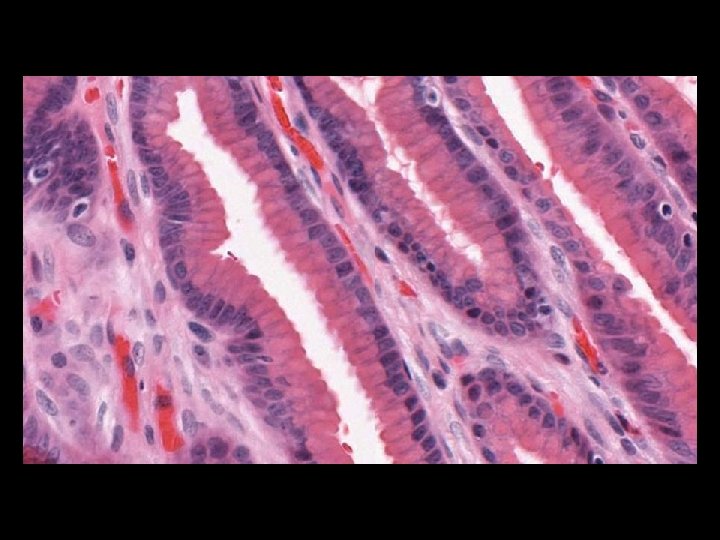
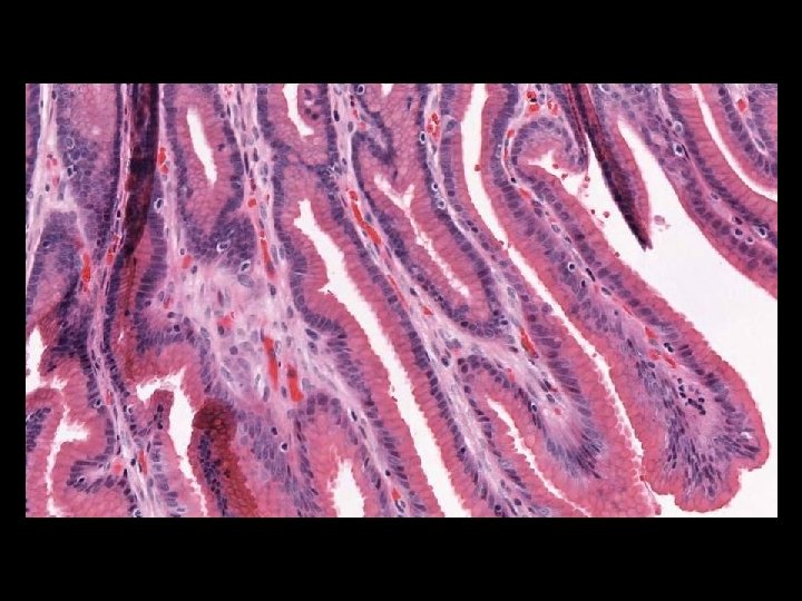
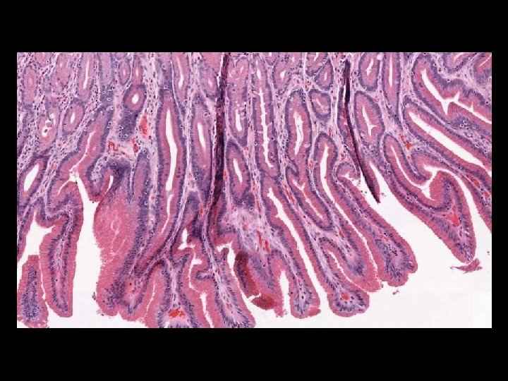
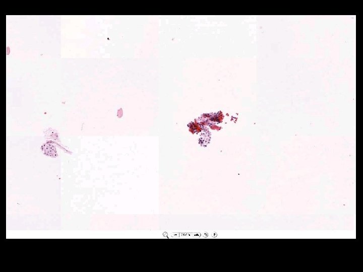
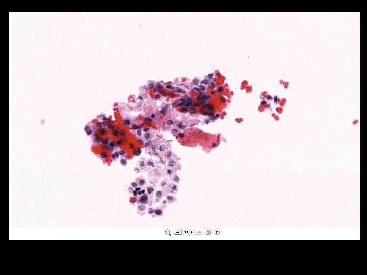
IMAGES
IMAGES
IMAGES
IMAGES
Aperio Scan. Scope T 2/T 3/CS Digital Slide Creation, Management, and Analysis Aperio's Scan. Scope Systems, comprised of award-winning Scan. Scope scanners and Digital Slide Information Management Software, deliver integrated digital slide creation, viewing, management, and analysis capabilities for virtual microscopy applications. Scan. Scope Systems are invaluable to pathologists for a multitude of applications, including education, tissue microarrays, toxicology pathology, telepathology, image analysis and workflow systems (PACS).
Hamamatsu
DMetrix Strategy for rapid throughput of pathology specimens: Glass slides are immediately scanned with an ultra-rapid virtual slide processor and read out by a telepathologists.
Trestle We Enhance the Efficiency of Research Operations Live review of slide over the internet or virtual slide creation Digital Microscopy Immediately available for viewing, diagnosis and consults worldwide Full Integrated case management, LIS integration and report generation Trestle provides an integrated, modular research solution
Work to be presented: In this paper we describe the nature of whole slide images and integration of whole slide imaging into the existing workflow of a pathology department. Using an image v glass slide equivalence study in anatomic pathology quality assurance as a context, we will discuss changes required in the Laboratory Information System (LIS) and Histology Laboratory to support image level information, departmental decisions surrounding the dissemination of images, the integration of imaging systems and the LIS and the development of a “DICOM wrapper” to communicate gross and histological images from Pathology to an Enterprise Image Archive.
Whole slide image clinical validation studies • • 3 pathologists 25 full cases, same workflow (3 -24 slides) 200 -500 whole slide images per study Integration of images with clinical information, histology information (ie staining) and workflow information (ie case status) • Security issues • Significant logistical effort
Goal To create a whole slide image delivery system for pathologists for clinical sign-out responsibilities *requires AP LIS integration, but workflow will reside in the AP LIS
Whole Slide Imaging at UPMC The ability to digitize an entire histologic slide at high resolution and display the resulting image across a broadband network - is becoming an important technology for telepathology and Pathology Imaging Current Spec. Hardware Specification Resolution: 0. 47 um/pixel(20 x) 0. 23 um/pixel (40 x) Speed: 40 mm 2/min File format: Tiff/Jpeg 2000 (Pyramid) Bar code: 2 D Autoloader: 120 slides
Scanning Process • Place Slides(120) in Autoloader • Push “Start” bottom – – – – Change slide (30 s) Bar Code reading Tissue finding Auto focus Scan (strip) Compression (on board) Stitch Feeding Virtual slide image to the storage Ave. 3 -10 min/slide, about 7 hours for 120 slides Image size 1 -8 GB File size 20 -600 MB
Image Capture Barcode Thumbnail WSI Robot Base image Pyramidal image
Each vendor has its own formats, servers and clients WSI Robot 1 Vendor Server 1 Client Pathologist WSI Robot 2 Vendor Server 2 Client Pathologist WSI Robot 3 Vendor Server 3 Client Pathologist WSI Robot 4 Vendor Server 4 Client Pathologist
No real integration with LIS or Security Vendor machine WSI Robot LIS System WSI Presentation Server Client Pathologist WSI DB WSI Storage Security System
Better structure LIS Client Pathologist WSI Robot 1 Client Pathologist WSI Robot 2 metadata WSI Image Import Server WSI Image Presentation Server Client Pathologist WSI Robot 3 Process 1 WSI Robot 4 UPMC Domain Server Process 2 Client Pathologist
Process 1 LIS Barcode elements Patient/specimen elements WSI Image Import Server metadata From WSI Robot Looks for new whole slide images Pulls new images Decodes the 2 D barcode Verifies slide/accession info with APLIS Fetches specimen/patient info from APLIS Constructs XML metadata wrapper Reconstructs file Sends file to WSI Image server To Process 2
Metadata wrapper • • • UID: 1. 2. 840. 152371. 157. 229. 222. 79. 20050706. 121311. 30. 1 XML Patient level (last name, first name, med rec num, sex, birthdate…) Accession level (Accession number, date, time, pathologist…) Study level (Modality, date, time, manufacturer, IP address…) Series level (whole slide image) – – – Part Block Slide number Stain Components and descriptions (thumbnail, label, base image…) • Image level (describes each component)
Example of metadata wrapper • • • • • • • <Series. Level> #A Series is effectively one slide imaged one time. #A Series has multiple images usually in a TIFF container #Some images are "real" optical images, others are sampled as part of a Pyramid: <S. 1> #Series Identification: <UID>1. 2. 840. 152371. 157. 229. 221. 31. 20050322. 112447. 30. 1< /UID> <Part. Number>1</Part. Number> <Block. Number>A</Block. Number> <Slide. Number>1</Slide. Number> <Part. Description>Colon Resection</Part. Description> <Block. Description>Proximal Margin</Block. Description> <Series. Begin. Time>143456</Series. Begin. Time> <Series. End. Time>144056</Series. End. Time> <Series. File. Description>WSITIFF</Series. File. Description> <Pixel. Size>N/A</Pixel. Size> <Series. Comment>NA</Series. Comment> <Paths> <P. 1>C: Image QualityImagesFocus MeasureYukako Images</P. 1> </Paths> <Images> <I. 1>Thumbnail. jpg</I. 1> <I. 2>Slide. Label. tif</I. 2> <I. 3>Base. Image. jp 2</I. 3> <I. 4>Level 1 Image. jp 2</I. 4> <I. 5>Level 2 Image. jp 2</I. 5> <I. 6>Scout. Camera. Image. jpg</I. 6> </Images> • • • • • • <DICOMMeta. Tags> <x 0002>1. 2. 840. 10008. 5. 1. 4. 1. 1. 7</x 0002> <x 00020003>1. 2. 840. 152371. 157. 229. 221. 31. 20050322. 112 447. 30</x 00020003> <x 00020010>1. 2. 840. 10008. 1. 2. 4. 50</x 00020010> <x 00020016>Simple. DICOMWrap</x 00020016> <x 00080005>ISO_IR 100</x 00080005><!-- specific character set --> <x 0008>ORIGINAL\PRIMARY</x 0008><!-- Image type --> <x 00080016>1. 2. 840. 10008. 5. 1. 4. 1. 1. 7</x 00080016><!-SOP class UID --> <x 00080018>1. 2. 840. 152371. 157. 229. 221. 31. 20050322. 112 447. 30. 1. 1</x 00080018><!-- SOP instance UID --> <x 00080020>20050322</x 00080020><!-- Study Date --> <x 00080023>20050322</x 00080023><!-- Content Date --> <x 00080030>112447</x 00080030><!-- Study Time --> <x 00080033>112447</x 00080033><!-- Content Time --> <x 00080050>1234</x 00080050><!-- Accession Number --> <x 00080060>OT</x 00080060><!-- Modality --> <x 00080070>Olympus</x 00080070><!-- Manufacturer --> <x 00080080>UPMC Presbyterian</x 00080080><!-- Institution Name --> <x 00080090>Dr. John Kirkwood</x 00080090><!-- Referring Physician's Name --> <x 00081010>Olympus CC 12</x 00081010><!-- Station Name --> <x 00081030>N/A</x 00081030><!-- Study Description --> <x 0008103 E>N/A</x 0008103 E><!-- Series Description --> <x 00081040>MEDICAL MEDIA</x 00081040><!-- Institutional Department Name --> <x 00081060>Number Two</x 00081060><!-- Name of Physician(s) reading study -->
Better structure LIS Client Pathologist WSI Robot 1 Client Pathologist WSI Robot 2 metadata WSI Image Import Server WSI Image Presentation Server Client Pathologist WSI Robot 3 Process 1 WSI Robot 4 UPMC Domain Server Process 2 Client Pathologist
Process 2 Client Pathologist WSI Image Presentation Server WSI Image Import Server Client Pathologist metadata Process 2 • Receives the image • Parses metadata wrapper • Writes database entry • Stores the image • Updates LIS on image status • Fetches image’s context • Serves the image Co. Path Client Pathologist
System communicates image status to LIS
Results & Discussion The work revealed a number of structural and procedural issues in the LIS, Imaging System and Archive the hindered the implementation of large scale imaging in pathology. Some of these issues include: • • LIS systems did not support the concept of an whole slide image Current pathology imaging systems did not well support the “groups of associated images (i. e. “series”) • The Enterprise Image Archive had difficulties with the size of the WSI and the proprietary internal structure of some of the WSI image files. The team implemented a series of work-arounds for these problems and tested them as part of clinical evaluations. On the basis of there results, we are working to develop long term solutions.
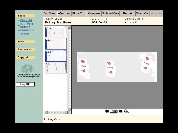
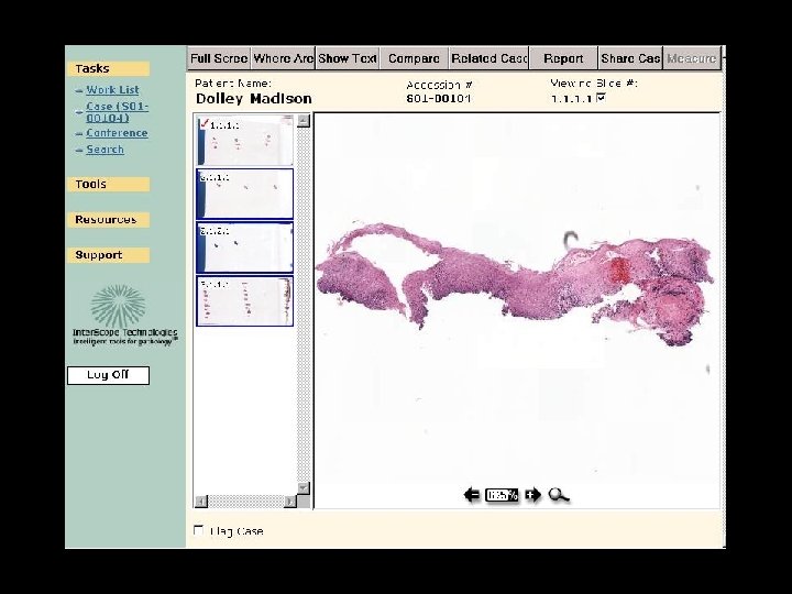
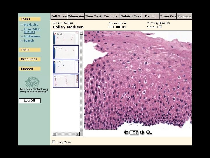
Integrated Clinical Application
Old cases on this patient Is this patient on a conference list etc Does case need QA, etc
Final thoughts • The real world – Multiple vendors – Multiple information systems to interface with • Difficulties we encountered – LIS limitations (Unique slide problem) – Lack of standard for modality output format – Lack of DICOM standards for whole slide images
After DICOM Standard? LIS Client Pathologist WSI Robot 1 DICOM Client Pathologist WSI Robot 2 DICOM WSI Image Presentation Server metadata DICOM Client Pathologist WSI Robot 3 DICOM Client Pathologist DICOM WSI Robot 4 UPMC Domain Server Client Pathologist
Thank you!