Extraoral and Digital Radiography Chapter 42 Copyright 2009


- Slides: 54

Extraoral and Digital Radiography Chapter 42 Copyright © 2009, 2006 by Saunders, an imprint of Elsevier Inc. All rights reserved.

Chapter 42 Lesson 42. 1 Copyright © 2009, 2006 by Saunders, an imprint of Elsevier Inc. All rights reserved.

Learning Objectives Pronounce, define, and spell the Key Terms. Describe the purpose and uses of panoramic radiography. Describe the equipment used in panoramic radiography. Describe the steps for patient positioning in panoramic radiography. Describe the errors caused during patient preparation and positioning during panoramic radiography. Discuss the advantages and disadvantages of panoramic radiography. Copyright © 2009, 2006 by Saunders, an imprint of Elsevier Inc. All rights reserved.

Introduction Extraoral radiographs (outside the mouth) are taken when large areas of the skull or jaw must be examined or when a patient is unable to open his or her mouth for film placement. Extraoral radiographs do not show the details as well as intraoral films do. Extraoral radiographs are useful in evaluating large areas of the skull and jaws but are not adequate for detection of subtle changes such as the early stages of dental caries or periodontal disease. There are many types of extraoral radiographs. Some types are used to view the entire skull, whereas other types are focused on the maxilla and mandible. Copyright © 2009, 2006 by Saunders, an imprint of Elsevier Inc. All rights reserved.

Panoramic Radiography Panoramic radiographs show the entire dentition and related structures on a single film. Some types of panoramic units operate with the patient in a seated position, and other types require the patient to be in a standing position. Regardless of the type of machine, you must follow the manufacturer’s instructions carefully. Because the images on a panoramic film are not as clear or as well defined as the images on intraoral films, bite-wing films are used to supplement a panoramic film to detect dental caries or periapical lesions. Copyright © 2009, 2006 by Saunders, an imprint of Elsevier Inc. All rights reserved.

Basic Concepts In panoramic radiography the film and tubehead rotate around the patient to produce a series of individual images. The term panorama means “an unobstructed view of a region in any direction. ” When the series of images are combined onto a single film, an overall view (panorama) of the maxilla and mandible is created. Copyright © 2009, 2006 by Saunders, an imprint of Elsevier Inc. All rights reserved.

Fig. 42– 1 A, Panoramic radiograph. B, Panoramic anatomy. (From Haring J, Jansen L: Dental radiography: principles and techniques, ed 2, Philadelphia, 2000, Saunders. ) Copyright © 2009, 2006 by Saunders, an imprint of Elsevier Inc. All rights reserved.

Fig. 42 -2 The film and x-ray tubehead move around the patient in opposite directions in panoramic radiography. (From Haring J, Jansen L: Dental radiography: principles and techniques, ed 2, Philadelphia, 2000, Saunders. ) Copyright © 2009, 2006 by Saunders, an imprint of Elsevier Inc. All rights reserved.

The Focal Trough The focal trough is an imaginary horseshoeshaped three-dimensional area. This is a very important concept because many errors in technique are caused by improper positioning of the patient’s jaws within the focal trough. When the jaws are positioned within this area, the radiograph will be clear. When the jaws are positioned outside this area, the images on the radiograph will appear blurred or indistinct. Copyright © 2009, 2006 by Saunders, an imprint of Elsevier Inc. All rights reserved.

Fig. 42 -3 Example of an image layer, or focal trough. (From Haring J, Jansen L: Dental radiography: principles and techniques, ed 2, Philadelphia, 2000, Saunders. ) Copyright © 2009, 2006 by Saunders, an imprint of Elsevier Inc. All rights reserved.

Components of the Panoramic Unit Panoramic x-ray tubehead Head positioner Exposure controls Copyright © 2009, 2006 by Saunders, an imprint of Elsevier Inc. All rights reserved.

Fig. 42 -4 Main components of a panoramic unit. Copyright © 2009, 2006 by Saunders, an imprint of Elsevier Inc. All rights reserved.

The Head Positioner Each panoramic unit has a head positioner, used to align the patient’s teeth as accurately as possible. Each head positioner consists of a chin rest, notched bite-block, forehead rest, and lateral head supports or guides. Each panoramic unit is different, and the operator must follow the manufacturer’s instructions on how to position the patient in the focal trough. Copyright © 2009, 2006 by Saunders, an imprint of Elsevier Inc. All rights reserved.

Fig. 42 -5 The head positioner (notched bite-block, forehead rest, and lateral head supports) is used to align the patient’s teeth in the focal trough. Copyright © 2009, 2006 by Saunders, an imprint of Elsevier Inc. All rights reserved.

Common Errors Patient-preparation errors Ghost images: A ghost image looks like the real object, except that it appears on the opposite side of the film. Ø Lead-apron artifact: If the lead apron is placed too high, or if a lead apron with a thyroid collar is used, a cone-shaped radiopaque artifact results. Ø Patient-seating errors Chin is too high. Ø Chin is too low. Ø Copyright © 2009, 2006 by Saunders, an imprint of Elsevier Inc. All rights reserved.

Fig. 42 -6 Large hoop earrings (1) and ghost images (2). The ghost image of the earring appears on the opposite side of the film and is enlarged and laterally distorted. (From Haring J, Jansen L: Dental radiography: principles and techniques, ed 2, Philadelphia, 2000, Saunders. ) Copyright © 2009, 2006 by Saunders, an imprint of Elsevier Inc. All rights reserved.

Fig. 42 -7 On a panoramic radiograph, a lead-apron artifact appears as a large cone-shaped radiopacity obscuring the mandible. (From Haring J, Jansen L: Dental radiography: principles and techniques, ed 2, Philadelphia, 2000, Saunders. ) Copyright © 2009, 2006 by Saunders, an imprint of Elsevier Inc. All rights reserved.

Fig. 42 -8 If the tongue is not placed on the roof of the mouth, a radiolucent shadow will be superimposed over the apices of the maxillary teeth. (From Haring J, Jansen L: Dental radiography: principles and techniques, ed 2, Philadelphia, 2000, Saunders. ) Copyright © 2009, 2006 by Saunders, an imprint of Elsevier Inc. All rights reserved.

Fig. 42 -9 Patient’s head is incorrectly positioned; the chin is tipped upward. Copyright © 2009, 2006 by Saunders, an imprint of Elsevier Inc. All rights reserved.

Fig. 42 -10 “Reverse smile line” is seen on a panoramic radiograph when the patient’s chin is tipped upward. (From Haring J, Jansen L: Dental radiography: principles and techniques, ed 2, Philadelphia, 2000, Saunders. ) Copyright © 2009, 2006 by Saunders, an imprint of Elsevier Inc. All rights reserved.

Fig. 42 -11 Patient’s head is incorrectly positioned; the chin is tipped downward. Copyright © 2009, 2006 by Saunders, an imprint of Elsevier Inc. All rights reserved.

Positioning of the Teeth Posterior to focal trough Ø If the patient’s anterior teeth are not positioned in the groove on the bite-block and are either too far back on the bite-block or posterior to the focal trough, the anterior teeth appear “fat” and out of focus on the radiograph. Anterior to focal trough Ø If the patient’s anterior teeth are not positioned in the groove on the bite-block and are either too far forward or anterior to the focal trough, the teeth will appear “skinny” and out of focus. Copyright © 2009, 2006 by Saunders, an imprint of Elsevier Inc. All rights reserved.

Fig. 42 -14 This patient is biting too far back on the bite stick. Copyright © 2009, 2006 by Saunders, an imprint of Elsevier Inc. All rights reserved.

Fig. 42 -15 Anterior teeth appear widened and blurred on a panoramic radiograph when the patient is positioned too far back on the bite-block. (From Haring J, Jansen L: Dental radiography: principles and techniques, ed 2, Philadelphia, 2000, Saunders. ) Copyright © 2009, 2006 by Saunders, an imprint of Elsevier Inc. All rights reserved.

Fig. 42 -16 Anterior teeth appear narrowed and blurred on a panoramic radiograph when the patient is positioned too far forward on the bite-block. (From Haring J, Jansen L: Dental radiography: principles and techniques, ed 2, Philadelphia, 2000, Saunders. ) Copyright © 2009, 2006 by Saunders, an imprint of Elsevier Inc. All rights reserved.

Fig. 42 -17 If the patient is not standing erect, superimposition of the cervical spine (arrows) may be seen on the center of the panoramic radiograph. (From Haring J, Jansen L: Dental radiography: principles and techniques, ed 2, Philadelphia, 2000, Saunders. ) Copyright © 2009, 2006 by Saunders, an imprint of Elsevier Inc. All rights reserved.

Positioning of the Spine If the patient’s spine is not straight, the cervical spine will appear as a radiopaque artifact in the center of the film and obscure diagnostic information. Copyright © 2009, 2006 by Saunders, an imprint of Elsevier Inc. All rights reserved.

Chapter 42 Lesson 42. 2 Copyright © 2009, 2006 by Saunders, an imprint of Elsevier Inc. All rights reserved.

Learning Objectives Describe the purposes and uses of extraoral radiography. Describe the equipment used in extraoral radiography. Identify the specific purpose of each of the extraoral film projections. Describe the purposes and uses of digital radiography. Discuss the fundamentals of digital radiography. List and describe the equipment used in digital radiography. List and discuss the advantages and disadvantages of digital radiography. Copyright © 2009, 2006 by Saunders, an imprint of Elsevier Inc. All rights reserved.

Extraoral Radiography Extraoral radiographs provide images of larger areas such as the skull and jaws. In some instances an extraoral film may be necessary in a handicapped patient who cannot open his or her mouth for film placement or in a patient with swelling or severe pain who is unable to tolerate the placement of intraoral films. Extraoral films are also useful in patients who are uncooperative and may refuse to open their mouths. Images seen on an extraoral films are not as clear or as well defined as the images seen on intraoral radiographs. Copyright © 2009, 2006 by Saunders, an imprint of Elsevier Inc. All rights reserved.

Equipment Extraoral radiographs may be taken with the use of a standard intraoral x-ray machine. Special head positioning and beam alignment devices can be added to the standard x-ray unit to aid patient positioning. Panoramic x-ray units may also be fitted with a special device known as a cephalostat. The cephalostat includes a film holder and head positioner that allow the operator to easily position the patient. Copyright © 2009, 2006 by Saunders, an imprint of Elsevier Inc. All rights reserved.

The Grid A grid is a device used to decrease film fog and increase the contrast of the radiographic image. It does this by reducing the amount of scatter radiation that reaches an extraoral film during exposure. Scatter radiation causes film fog and reduces film contrast. Copyright © 2009, 2006 by Saunders, an imprint of Elsevier Inc. All rights reserved.

Fig. 42 -19 A grid decreases the amount of scatter radiation that reaches the extraoral film. (From Haring J, Jansen L: Dental radiography: principles and techniques, ed 2, Philadelphia, 2000, Saunders. ) Copyright © 2009, 2006 by Saunders, an imprint of Elsevier Inc. All rights reserved.

The Lateral Jaw Projection The lateral jaw projection is used to view the posterior region of the mandible. This type of projection is very useful in patients with limited jaw opening and in patients who cannot or will not tolerate intraoral film placement. A lateral jaw projection does not provide as much diagnostic information as a panoramic radiograph. The advantage is that the lateral jaw projection can be taken with a standard x-ray unit. Copyright © 2009, 2006 by Saunders, an imprint of Elsevier Inc. All rights reserved.

Lateral Jaw Projection Techniques Body of mandible projection Ramus of mandible projection Copyright © 2009, 2006 by Saunders, an imprint of Elsevier Inc. All rights reserved.

Fig. 42 -20 A, For the lateral jaw projection of the body of the mandible, proper patient and film positioning is shown as viewed from the front and side of the patient. B, Lateral jaw radiograph of mandibular body. (From Haring J, Jansen L: Dental radiography: principles and techniques, ed 2, Philadelphia, 2000, Saunders. ) B Copyright © 2009, 2006 by Saunders, an imprint of Elsevier Inc. All rights reserved.

The Ramus of the Mandible This film is used to evaluate impacted third molars, large lesions, and fractures that extend into the ramus of the mandible. The ramus from the angle of the mandible to the condyle is visible in this projection. Copyright © 2009, 2006 by Saunders, an imprint of Elsevier Inc. All rights reserved.

Fig. 42 -21 A, For the lateral jaw projection of the ramus of the mandible, proper patient and film positioning is shown as viewed from the front and side of the patient. B, Lateral jaw radiograph of mandibular ramus. (From Haring J, Jansen L: Dental radiography: principles and techniques, ed 2, Philadelphia, 2000, Saunders. ) B Copyright © 2009, 2006 by Saunders, an imprint of Elsevier Inc. All rights reserved.

Skull Radiography Lateral cephalometric projection Posteroanterior projection Water projection Submentovertex projection Reverse Towne projection Copyright © 2009, 2006 by Saunders, an imprint of Elsevier Inc. All rights reserved.

Fig. 42 -22 B, Lateral cephalometric radiograph. (From Haring J, Jansen L: Dental radiography: principles and techniques, ed 2, Philadelphia, 2000, Saunders. ) B Copyright © 2009, 2006 by Saunders, an imprint of Elsevier Inc. All rights reserved.

Fig. 42 -23 B, Posteroanterior skull radiograph. (From Haring J, Jansen L: Dental radiography: principles and techniques, ed 2, Philadelphia, 2000, Saunders. ) B Copyright © 2009, 2006 by Saunders, an imprint of Elsevier Inc. All rights reserved.

Fig. 42 -25 B, Submentovertex radiograph. (From Haring J, Jansen L: Dental radiography: principles and techniques, ed 2, Philadelphia, 2000, Saunders. ) B Copyright © 2009, 2006 by Saunders, an imprint of Elsevier Inc. All rights reserved.

Fig. 42 -26 B, Reverse Towne radiograph. (From Haring J, Jansen L: Dental radiography: principles and techniques, ed 2, Philadelphia, 2000, Saunders. ) B Copyright © 2009, 2006 by Saunders, an imprint of Elsevier Inc. All rights reserved.

Temporomandibular Joint Radiography Radiographs of the temporomandibular joint (TMJ) can be very difficult to examine because of the multiple adjacent bony structures. The articular disc and other soft tissues of the TMJ cannot be examined radiographically. Special imaging techniques (e. g. , arthrography, magnetic resonance imaging) must be used. Radiographic projections of the TMJ can be used to show the bone and the relationship of the jaw joint. Copyright © 2009, 2006 by Saunders, an imprint of Elsevier Inc. All rights reserved.

Fig. 42 -28 Patient positioned for a transcranial radiograph of the TMJ. Copyright © 2009, 2006 by Saunders, an imprint of Elsevier Inc. All rights reserved.

Digital Radiography Advances in digital technology have led to a unique “filmless” imaging system known as digital radiography. Introduced in 1987, digital radiography has influenced both how dental disease is recognized and how it is diagnosed. In the last 2 years, the use of digital radiography has increased rapidly in both general and specialty dental practices. Several companies are producing digital radiography systems. Copyright © 2009, 2006 by Saunders, an imprint of Elsevier Inc. All rights reserved.

The Basics of Digital Radiography Digital radiography uses a sensor (instead of film) to capture a radiographic image, breaking it into electronic pieces and storing the image in a computer. The patient is exposed to less x-radiation than with conventional radiography. The image is displayed on a computer screen rather than on film. The term image (not radiograph) is used to describe the pictures that are produced. (Cont’d) Copyright © 2009, 2006 by Saunders, an imprint of Elsevier Inc. All rights reserved.

The Basics of Digital Radiography (Cont’d) The x-ray beam strikes the sensor. An electronic charge is produced on the surface of the sensor, and this electronic signal is digitized. The digital sensor in turn transmits this information to the computer. Software on the computer is used to store the image electronically. Copyright © 2009, 2006 by Saunders, an imprint of Elsevier Inc. All rights reserved.

Fig. 42 -29 Digital radiographic system. Copyright © 2009, 2006 by Saunders, an imprint of Elsevier Inc. All rights reserved.

Fig. 42 -30 A, Size of the electronic sensor is compared with traditional intraoral film in sizes 0, 1, and 2. B, Electronic sensor is protected with a plastic barrier and is ready for positioning in the patient’s mouth in the same manner as that of a traditional film and holder. (Courtesy of Michael Danford, Santa Rosa, Calif. ) A B Copyright © 2009, 2006 by Saunders, an imprint of Elsevier Inc. All rights reserved.

Radiation Exposure Digital radiography requires much less xradiation than conventional radiography does because the sensor is more sensitive to xrays than is conventional film. Exposure times for digital radiography are 50% to 80% less than that required for radiography using conventional film. With less radiation, the dose absorbed by the patient is significantly lower. Copyright © 2009, 2006 by Saunders, an imprint of Elsevier Inc. All rights reserved.

Equipment For digital radiography, special equipment is required. The essential components include: Dental x-ray unit Ø Intraoral sensor Ø Computer Ø Copyright © 2009, 2006 by Saunders, an imprint of Elsevier Inc. All rights reserved.

Types of Digital Imaging There are three types of digital imaging: Direct Indirect Storage phosphor The difference between the methods lies in how the image is obtained and in what size the receptor plates are available (e. g. , panoramic). Copyright © 2009, 2006 by Saunders, an imprint of Elsevier Inc. All rights reserved.

Fig. 42 -31 All types of radiographs may be produced in digital format. Copyright © 2009, 2006 by Saunders, an imprint of Elsevier Inc. All rights reserved.
 Dental radiography techniques ppt
 Reverse towne projection
 Copyright 2009 pearson education inc
 Copyright international color consortium, 2009
 Dell all rights reserved copyright 2009
 Copyright 2009 pearson education inc
 Reticolo di diffrazione zanichelli
 Copyright 2009
 Copyright 2009
 Copyright 2009 pearson education inc
 2009 pearson education inc
 Copyright 2009 pearson education inc
 Copyright 2009 pearson education inc
 Intraoral scanner comparison
 Extraoral gothic arch tracing
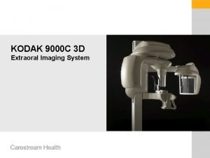
 Kodak 9000
 Extraoral examination in orthodontics
 Reverse townes view positioning
 Palm up extraoral fulcrum
 Recorded detail in radiography
 Soot and whitewash radiography
 Additive and destructive pathology
 Different tones
 Us digital millennium copyright act autumn
 Focal trough in panoramic radiography
 8:1 grid
 Emulsion peel in radiography
 Latent image formation in radiography
 Filmless radiography
 Computed radiography cassette
 Radiography safety precautions
 Measurement equipment shelves, darkroom
 Radiography cordon off distance formula
 Optical density formula
 Linear focused grid
 Gurney-mott theory radiography
 Industrial radiography accidents
 Radiography
 Occlusal radiograph
 Industrial radiography accidents
 Rni radiography
 Kv m
Kv m Industrial radiography training
 Limitations of radiography
 Buccal object rule dental radiography
 What is computed radiography
 Mask mode radiography
 Combining spatial enhancement methods
 Histogram equalization
 Uretorocele
 Recumbent position
 E-commerce: digital markets, digital goods
 Discrepancy matrix morrison and wonnacott 2009
 Coroners and justice act 2009
 Saunders lewis and thornhill 2009
