Radiography of cranial Bones Basic 0 Occipito frontal

Radiography of cranial Bones
 ● AP Axial 30°")
Basic ● 0° Occipito -frontal ● 15° Occipito-frontal ( Caldwell) ● AP Axial 30° Fronto- Occipital ( Townes) ● Sub-mento vertical ( SMV)

Trauma Series Cranium ● 0° Fronto occipital ● 20° Fronto occipital ● Lateral ( Horizontal Beam ) Cranium (Sella Turcica) Basic ● Lateral ● AP Axial ( Townes )

0° Occipito- frontal Exposure factors KV m. As FFD Focus Grid Film/Screen combination 80 40 100 Fine Yes Regular Patient Position Patient prone or sits erect facing the bucky. Part Position Rest patient’s nose and forehead against the bucky. Align midsagittal plane perpendicular to and in line with the midline of bucky and central ray. Tuck chin in to bring the OML 90° to film. Centre bucky to Glabella Central Ray Horizontally & perpendicular to film holder Centre Point Exit through the Glabella
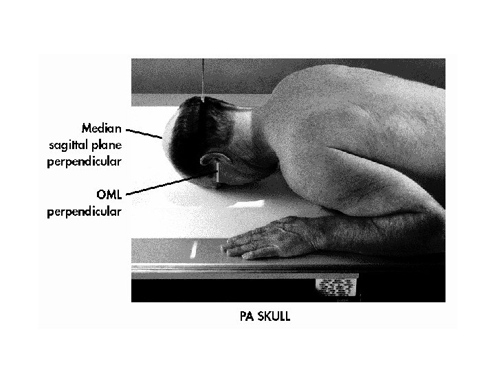

Anatomy Demonstrated Frontal bone, crista galli, internal auditory canals, frontal and ethmoid sinuses, petrous ridges, greater and lesser wings of sphenoid bone
 Exposure factors KV m. As FFD Focus Grid Film/Screen combinat ion")
15° Occipito-frontal (Caldwell) Exposure factors KV m. As FFD Focus Grid Film/Screen combinat ion 80 40 100 Fine Yes Regular Patient Position Patient Prone or sits erect facing the bucky. Part Position Rest patient’s nose and forehead against the bucky. Align midsagittal plane perpendicular to and in line with the midline of bucky and central ray. Tuck chin in to bring the OML 90° to film. Centre bucky to Nasion Central Ray Angled 15° Caudally Centre Point Exit through the Nasion
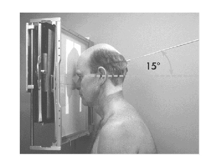

Anatomy Demonstrated Frontal bone, crista galli, Orbital margin, frontal and ethmoid sinuses, petrous ridges, greater and lesser wings of sphenoid. Petrous pyramids projected into lower 1/3 of the orbits
 Exposure factors KV m. As FFD Focus Grid 85 40")
30° Fronto Occipital (Townes) Exposure factors KV m. As FFD Focus Grid 85 40 100 Fine Yes Film/Screen combination Regular Patient Position Patient supine or sits erect A. P. against the bucky Part Position Align midsagittal plane perpendicular to and in line with the midline of bucky and central ray. Tuck chin in to bring the OML 90° to film Central Ray Angled 30° Caudally centre Point In the midline to a point 6 cm above the Nasion.
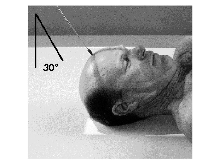

Anatomy Demonstrated Occipital bone, petrous pyramids, foramen magnum, dorsum sellae and posterior clinoids Dorsum sella and posterior clinoids are projected into the foramen magnum.
 Exposure factors KV m. As FFD Focus Grid 85 40 100 Fine")
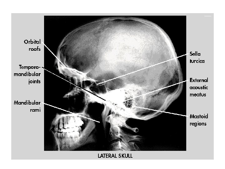
Lateral (Cranium) Exposure factors KV m. As FFD Focus Grid 85 40 100 Fine Yes Film/Screen combination Regular Patient Position Patient recumbent semi prone or sits erect facing the bucky, Part Position Rotate head to the side in question, to bring the median Sagittal plane parallel to the film. The angle of the OMB is adjusted for maximum patient comfort. The Interpupillary line should be parallel to the floor. Central Ray Perpendicular to film holder Centre Point To a point 2 cm superior and 2 cm anterior to the EAM.
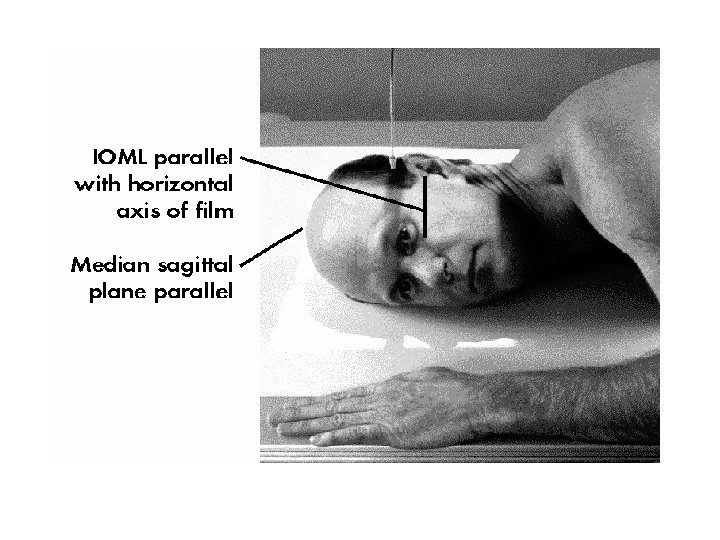

Anatomy Demonstrated Lateral aspect of cranium nearest to the film, dorsum sella, anterior and posterior clinoids, greater and lesser wings of sphenoid bone. Mandibular rami, orbital roofs, E. A. M. s and wings of sphenoid bone superimposed. Sella turcica seen in profile.
 Exposure factors KV m. As FFD Focus Grid 85 40")
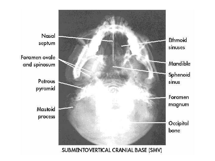
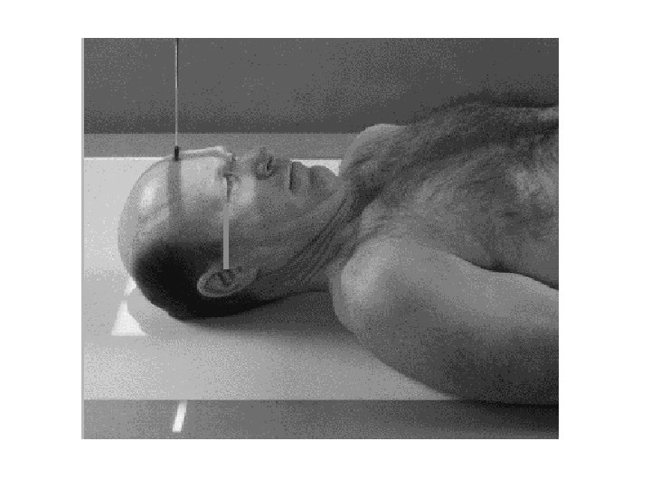
Sub-mento vertical ( SMV) Exposure factors KV m. As FFD Focus Grid 85 40 100 Fine Yes Film/Screen combination Regular Patient Position Patient supine or sits erect, with his back to the bucky Part Position. Take care with this technique; it is not suitable for trauma patients a small pillow is placed behind the shoulders and the patient extends the neck until the orbital Meatal baseline is parallel to the film the Interpupillary line parallel to the floor and the median sagittal plane at 90 degrees to the film Apply thyroid protection with lead rubber Central Ray Horizontally & perpendicular to film holder Centre Point Midway between the angles of the mandible
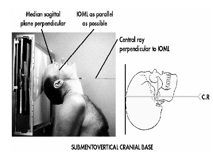

Anatomy Demonstrated Base of skull and associated foramina
 0° Fronto occipital 20° Fronto occipital Lateral ( Horizontal Beam")
Cranium Bones (Trauma Series) 0° Fronto occipital 20° Fronto occipital Lateral ( Horizontal Beam )

0° Fronto occipital Exposure factors KV m. As FFD Focus Grid 85 40 100 Fine Yes Film/Screen combination Regular Patient Position The patient lies supine on the trolley or x-ray table Part Position The midsagittal plane centred to centre of the table. The patients head is positioned so that the Interpupillary line is parallel to the film. The neck is flexed depressing the chin until the radiographic baseline (OMBL) is at 90 degrees to the film, * Not possible if there is a possible cervical injury) A small pad may be needed under the occipital or beneath the cassette Central Ray Perpendicular to film holder Centre Point To the Glabella

Anatomy Demonstrated Frontal bone, crista galli, internal auditory canals, frontal and ethmoid sinuses, petrous ridges, greater and lesser wings of sphenoid bone

20° Fronto occipital Exposure factors KV m. As FFD Focus Grid 85 40 100 Fine Yes Film/Screen combination Regular Patient Position The patient lies supine on the trolley or x-ray table Part Position The midsagittal plane centred to centre of the table. The patients head is positioned so that the interpupillary line is parallel to the film. The neck is flexed depressing the chin until the radiographic baseline (OMBL) is at 90 degrees to the film, * Not possible if there is a possible cervical injury) A small pad may be needed under the occipital or beneath the cassette Central Ray The vertical central ray is angled 20 degrees cranially Centre Point To the Glabella
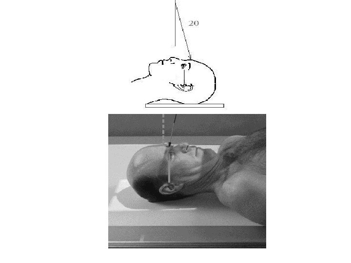

Anatomy Demonstrated Frontal bone, crista galli, Orbital margin, frontal and ethmoid sinuses, petrous ridges, greater and lesser wings of sphenoid. Petrous pyramids projected into lower 1/3 of the orbits
 Exposure factors KV m. As FFD Focus Grid 80 40 100")
Lateral (Horizontal Beam) Exposure factors KV m. As FFD Focus Grid 80 40 100 Fine Yes Patient Position The patient lies supine on the trolley or x-ray table Part Position Midsagittal plane aligned central to the table, The head is supported on a small pad, Side of interest nearest the film. the median sagittal plane must be parallel to the Film is placed vertically along side of the head. Central Ray Horizontally & perpendicular to film holder Centre Point To a point 2 cm superior and 2 cm anterior to the EAM Film/Screen combination Regular
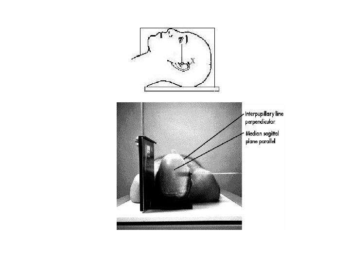

Anatomy Demonstrated Lateral aspect of cranium nearest to the film, dorsum sella, anterior and posterior clinoids, greater and lesser wings of sphenoid bone. Mandibular rami, orbital roofs, E. A. M. s and wings of sphenoid bone superimposed.
- Slides: 30