
Using the Holographic Back Projection in NSI 2000

Using the Holographic Back Projection in NSI 2000 NEARFIELD SYSTEMS, INC.

NSI 2000’s Holographic Back Projetion l In NSI 2000, one may perform a back projection to view amplitude and phase over the surface of an any aperture antenna. l The antenna shown to the right has a “faulty” element (slot covered with copper tape). NEARFIELD SYSTEMS, INC.
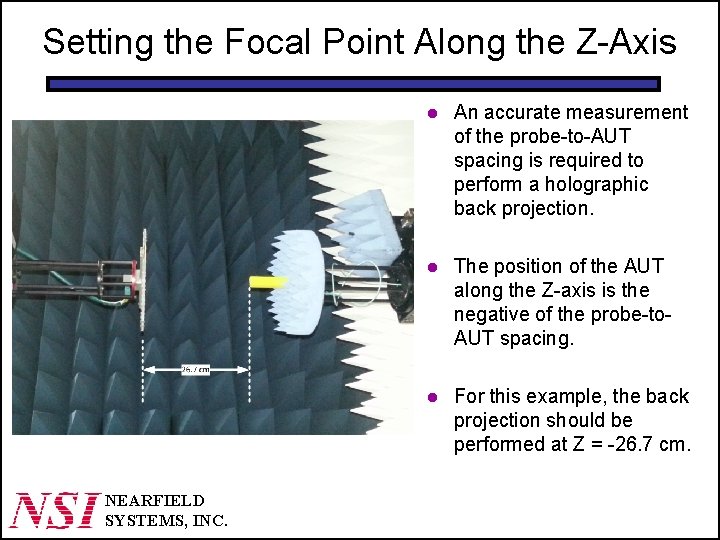
Setting the Focal Point Along the Z-Axis NEARFIELD SYSTEMS, INC. l An accurate measurement of the probe-to-AUT spacing is required to perform a holographic back projection. l The position of the AUT along the Z-axis is the negative of the probe-to. AUT spacing. l For this example, the back projection should be performed at Z = -26. 7 cm.
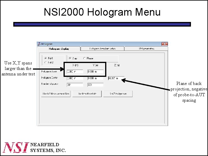
NSI 2000 Hologram Menu Use X, Y spans larger than the antenna under test Plane of back projection, negative of probe-to-AUT spacing NEARFIELD SYSTEMS, INC.
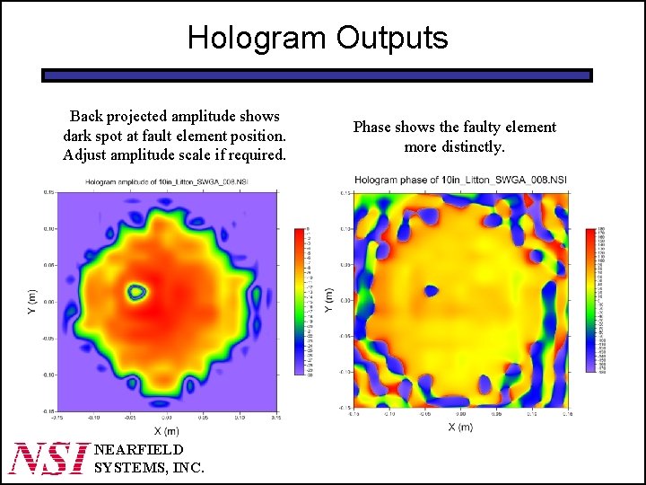
Hologram Outputs Back projected amplitude shows dark spot at fault element position. Adjust amplitude scale if required. NEARFIELD SYSTEMS, INC. Phase shows the faulty element more distinctly.
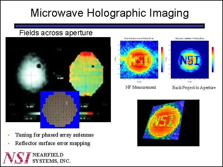
Microwave Holographic Imaging Fields across aperture NF Measurement • • Tuning for phased array antennas Reflector surface error mapping NEARFIELD SYSTEMS, INC. Back Project to Aperture
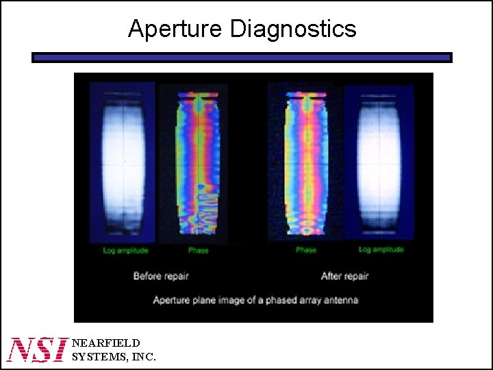
Aperture Diagnostics NEARFIELD SYSTEMS, INC.
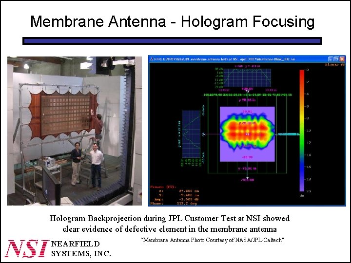
Membrane Antenna - Hologram Focusing Hologram Backprojection during JPL Customer Test at NSI showed clear evidence of defective element in the membrane antenna NEARFIELD SYSTEMS, INC. “Membrane Antenna Photo Courtesy of NASA/JPL-Caltech"
- Slides: 8