LIQUID AND SOLID INSULATION Lecture 4 ELECE 8409


![MINERAL OIL Ub [k. V] Most common liquid insulation • Typical mineral oil is](https://slidetodoc.com/presentation_image/2443644ca60bf93888ef2e9ca4c3dded/image-5.jpg "MINERAL OIL Ub [k. V] Most common liquid insulation • Typical mineral oil is")


 will expand across")


 Paper (oil impregnated) Organic Rubber Synthetic Polymer")


 BREAKDOWN Intrinsic strength is a property of the MATERIAL and TEMPERATURE only")


 components so that their distance to grounded")

 146 Æ162 Disk Insulator, Cap and Pin")


 DC:")
 10 – 50 mm wide paper tape wrapped around the")

 are placed")


 no grading b. ) geometric grading c. ) refractive grading Permittivity-based grading")

 A live conductor is fed through a grounded enclosure To avoid")


- Slides: 49
LIQUID AND SOLID INSULATION Lecture 4 ELEC-E 8409 High Voltage Engineering
LIQUID INSULATION Requirements Examples Breakdown
PURPOSE • Protect solid insulation from discharge • Extinguish arcing • Efficiently remove heat (cooling) REQUIREMENTS • Low viscosity (resistance of fluid - thickness) • Cooling properties • Liquid fills all voids in solid insulation • Viscosity must remain small at low temperatures (Finland) • Cannot become solid. Solidification temperature less than -40 °C) • Chemically stable • Maintain insulating properties through long service life in varying conditions
REQUIREMENTS DEPEND ON APPLICATION: Transformers • High withstand voltage – high dielectric strength of liquid • Good heat transfer capability for cooling • High resistivity, low loss factor, good PD tolerance Cables and Bushings • Very good PD tolerance • Very low viscosity (impregnation) Switches • High flash temperature so that it can safely extinguish arc
MINERAL OIL Ub [k. V] Most common liquid insulation • Typical mineral oil is transformer oil • Easy availability and economical • Properties defined in IEC 60296 • Good dielectric properties for insulation and low viscosity for cooling • Prone to oxidization and flammability (flash point over 130 °C) • Moisture and impurities affect insulating properties 80 (ii. ) same oil filtered twice 60 40 20 0 (i. ) clean industrial transformer oil 0 20 40 60 80 100 water content [µg/g]
SYNTHETIC LIQUID INSULATION CONTROLLED CHEMICAL STRUCTURE DESIRED PROPERTIES MORE EXPENSIVE Relative Permittivity εr [50 Hz, 25 °C] Kinematic Viscosity [mm 2/s, 20 °C] Solidification Point [°C] Flashpoint [°C] Mineral Oil 2. 2 16 -50 150 -175 Mono/dibenzyl toluene 2. 7 6. 5 -50 144 Very toxic for aquatic environment Comments Silicone Oil 2. 9 50 -53 >335 Most environmentally friendly Non-flammable Poor heat transfer. Poor discharge tolerance (flammable gas by-products from arcing) Ester 3. 3 63 -50 310 Non-toxic, Environmentally friendly
BREAKDOWN IN LIQUID INSULATION In relatively clean and homogenous liquids, the breakdown mechanism is similar to breakdown in gas Electric field is applied to the charge carriers in the liquid (electrons already present in the liquid and those released from the cathode through emission and electrochemical processes) Electrons move in the opposite direction of the field If the energy of the electrons is sufficient, dissociation of molecules by collisional ionization occurs (ionic compounds split into smaller particles – opposite of recombination) Microscopic gas bubbles form in liquid Due to the density of the liquid, it is hard for electrons to achieve much energy between collisions Townsend avalanches and new free charges can form in the BUBBLES (smaller density)
BREAKDOWN IN LIQUID INSULATION Eventually the bubble (or row of bubbles) will expand across the electrode gap Mobility of electrons in the liquid is 105 times greater than positive ions • an ionized channel is formed and advanced by streamer discharge • electrons leave behind a concentration of positive ions • the channel has lower density and smaller dielectric strength than the rest of the liquid • these charge concentrations enhance electric field in certain regions and further advance ionization • continuous current flows through the channel Free charges created by ionization inside the bubble are displaced by the electric field • the bubble is stretched and grows in size
BREAKDOWN IN LIQUID INSULATION Breakdown can also be caused by impurities Impurity. ɛr > Liquid. ɛr • Impurity moves towards the area of highest electric field • Impurity enhances the electric field and attracts other particles • These particles bridge the electrodes leading to breakdown Moisture and foreign particles Fiber bridge Bridging of impurities and bubble rows can be avoided by • Inter-layering with solid insulation • Displacing liquid (flowing)
BREAKDOWN IN LIQUID INSULATION Dielectric strength of liquid is hard to determine: Temperature and pressure affect the liquid’s dielectric strength • not constant • once oxidation, electrochemical temperature As increases, viscosity decrease • which reactions, and impurities affect increases the speed of electrons between the liquid, its insulating collisions and increase the probability for properties are not the same breakdown • dielectric strengthbubbles offormation liquid pressure increases, ofthe As • measured in homogeneous gap is more difficult which improves the dielectric even though most insulators are strength of the liquid. inhomogeneous
SOLID INSULATION Requirements Examples Breakdown
PURPOSE • Mechanical support for conducting components • Electrical insulation REQUIREMENTS • Mechanical strength • Dielectric strength • Heat tolerance
Insulation Organic Nonorganic Synthetic Polymer Paper (dry) Paper (oil impregnated) Organic Rubber Synthetic Polymer Temperature Index TI (20 000 h) [°C] 6 90 40 – 75 105 20 75 Wood (dry) 90 Wood (oil impregnated) 105 Press wood (dry) Inorganic Breakdown Field Strength [k. V/mm] 6 90 – 120 Porcelain 30 1000 Glass 16 400 – 1000 Mica 80 500 – 700 Polythene 20 105 Polystyrene 100 80 – 90 5 – 16 120 – 155 Epoxy plastic 20 – 40 105 – 155 Melamine 13 – 14 120 Phenolic plastic (bakelite) Comments • • • easy to handle and machine typically good dielectric properties insulating properties change during service life temperatures above 100 °C deteriorate insulator typically porous – absorb liquids, impregnation transformers, cables, capacitors • withstand high temperatures • excellent dielectric and mechanical properties • poor machinability, cannot absorb liquids • overhead lines, bushings, rotating machines • all industrially produced solid insulation • excellent electric properties, easy to machine • thermoplastic / thermoset plastic • wide range of applications depending on manufacturing process - moisture sealing, tensile strength, flexibility
BREAKDOWN IN SOLID INSULATION Mechanism of breakdown in solids remains unclear When voltage stress is increased close to breakdown: • Current through insulator increases exponentially (similar to gas) • Assumed to be caused by increasing number of charge carriers in the insulation and electrode surfaces In practice, other factors affect breakdown besides the increase of electrons: F 12 F 21 • Pre-discharge current and dielectric losses causing heat • Electrostatic forces at interfaces • Electrochemical reactions • Water trees, erosion
BREAKDOWN IN SOLID INSULATION In general: Breakdown is caused by energy provided by an electric field Energy transfer can occur by: 1. Collision Ionization (electric breakdown) 2. Thermal Losses (thermal breakdown) Breakdown leads to thermal destruction of insulator (melting, charring, vaporizing) Permanent loss of insulating properties (not self-restoring like gases)
BREAKDOWN IN SOLID INSULATION BREAKDOWN MECHANISMS IN SOLID INSULATION • • Electrical Breakdown Intrinsic Breakdown Partial Discharge Electrical Treeing Electromechanical Breakdown Thermal Breakdown Electrolytic Breakdown
ELECTRICAL BREAKDOWN Multi-stage phenomenon influenced by: • • Different ionization mechanisms Space charges in discharge channel Heating of insulator material Molecular structure deformations Discharge occurs when critical field strength is exceeded locally Conducting channel with numerous charge carriers starts to progress • assumed to begin at inhomogeneous region of the insulation or electrode surface Insulation is destroyed by different chemical and physical processes Complete breakdown occurs when the channel has bridged the electrodes
INTRINSIC (INTERNAL) BREAKDOWN Intrinsic strength is a property of the MATERIAL and TEMPERATURE only In pure homogeneous dielectric materials the conduction and valence bands are separated by a large energy gap and at room temperature the electrons cannot acquire sufficient thermal energy to make transitions from valence to conduction band. When an electric field is applied, the conduction electrons gain energy due to collisions between them and the energy is shared by all electrons. electron energy • For a stable condition, this energy must be somehow dissipated. • The field raises the energy of the electrons more rapidly than they can transfer it to the lattice. • Electron temperature increases and conduction continues to increase to a complete breakdown. metal semiconductor insulator conduction band Fermi level band gap valence band The energy gained by electrons from the electric field exceeds the amount of energy that electrons can transfer, resulting in the collapse of the entire molecular lattice
PARTIAL DISCHARGE BREAKDOWN Insulators usually have voids or gas bubbles If the void has lower permittivity than its surrounding material, voltage stress is higher inside the void Positive ions and electrons released by the discharge collide with the void wall causing slow erosion Once the void’s withstand strength is exceeded, partial discharge begins (discharge byproducts can also cause chemical erosion) Irregularities in the void wall enhance the electric field locally As further discharges concentrate on this area, the erosion path is advanced
ELECTRICAL TREEING If stress is continuous, eventually discharges will advance through a solid insulator in a branching erosion path (electric tree) along which a complete breakdown can occur Treeing commences at impurities on the electrode or in the insulation (pre-breakdown phenomenon) Vented water treeing Bow tie water treeing Electrical treeing Water treeing – moisture advances in insulator under the influence of the electric field E. g. Chemical degradation of polymeric insulation such as XLPE or EPR that only occurs in the presence of water and electrical stress (initiates from inhomogenities within the insulation or at insulation/screen interface)
ELECTROMECHANICAL BREAKDOWN Mechanical force between charges at electrodes causes pressure (force of attraction between surface charges) Electrode distance decreases causing the electric field to further increase pressure The pressure forces the insulator to compress (not very common for typical insulators) Localized heating and softening of the insulator leads to mechanical collapse
ELECTROMECHANICAL BREAKDOWN Mechanical collapse when electrostatic compressive forces exceed mechanical compressive strength: Y = Young’s modulus of elasticity d 0 = original distance d = compressed distance Stress (E = U/d 0) required for collapse (d < 0. 6 d 0) PET (polyethylene terephthalate, thermoplastic polymer resin) ɛr = 3, Y = 3. 1 x 10⁹ Pa E = 6480 k. V/mm! Ba. Ti. O 3 (barium titanate, dielectric ceramic used in capacitors) ɛr = 18500, Y = 167. 4. 1 x 10⁹ Pa E = 607 k. V/mm!
THERMAL BREAKDOWN An electric field causes the insulator to experience heat produced by conductivity and dielectric losses 3 (E 3 ) 2 (E 2) heat gain as ipation o sc n’ the o wt ng oli • law 1 (E 1 ) Ne increases more heating • more dielectric losses If heat is being produced in the insulator faster than it is removed by cooling thermal breakdown t 1 t 2 specimen temperature 1. Field strength E 1: insulator temperature stabilizes at t 1 no thermal breakdown 2. Field strength E 2: temperature increases to t 2 unstable (small temporary fluctuation can lead to thermal breakdown) 3. Stabilization point unreachable thermal breakdown Heat produced at E 3 always exceeds cooling
ELECTROLYTIC BREAKDOWN Any substance containing free ions that behave as an electrically conductive medium Insulators with moisture and impurities are prone to electrolytic breakdown Highly dependant on local environmental conditions Electrolyte Ions (oxygen, chlorine) present in the insulator migrate to the electrodes causing a chemical reaction Ions transport conducting material from the electrodes into the interior of the dielectric Gradual build up (years) resulting in sudden breakdown
BREAKDOWN IN SOLID INSULATION Breakdown strength and discharge processes are highly dependent on stress Eb Electrical Breakdown Electromechanical Breakdown 105 duration Thermal Breakdown 104 Partial Discharge Electrical Treeing 103 10 -9 10 -6 10 -3 0 10 [s] 10 3 10 6 year Water Treeing 102 hour day [V/mm] 106 10 9 t
PRACTICAL INSULATORS OHL Components Cables Bushings
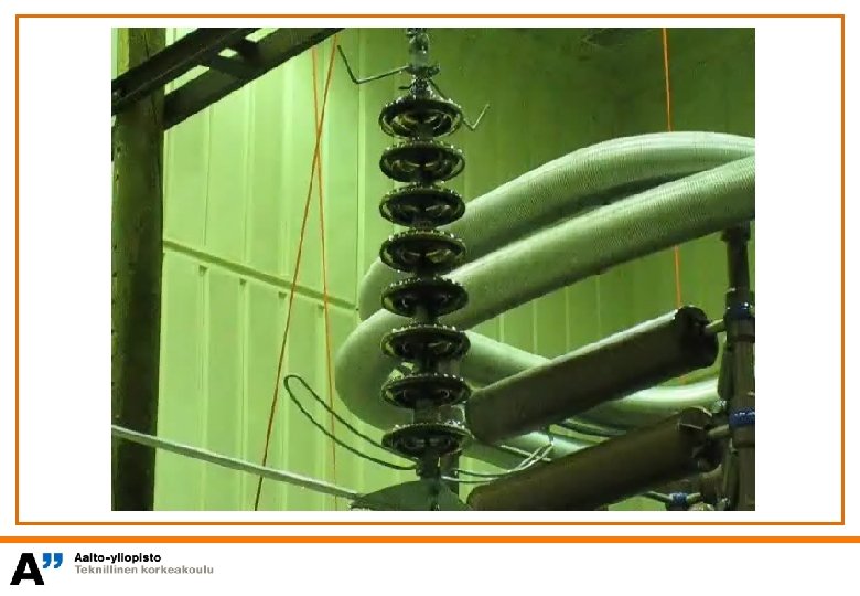
Insulators are needed to support live (voltage) components so that their distance to grounded parts and other devices is maintained. All organic insulators are influenced by temperature and stress duration Above certain temperature hard plastic becomes soft and its mechanical and dielectric properties degrade As temperature decreases plastic becomes brittle and its impact strength weakens All outdoor insulators need to consider: • • • Voltage withstand strength Surface distance Dirt accumulation prevention Self-cleaning (aerodynamic shape) Water sealing Mechanical strength – arcing, erosion, UV radiation, thermal reaction
a. b. c. d.
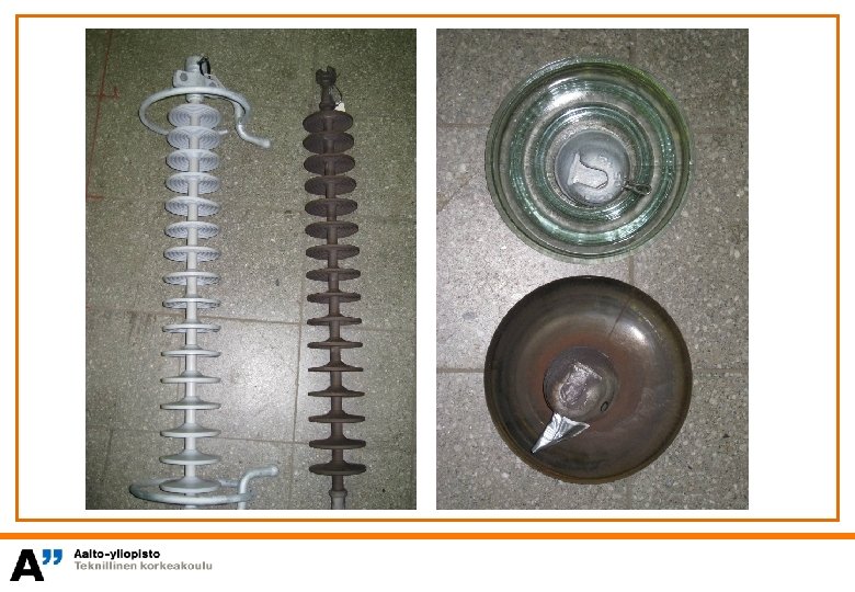
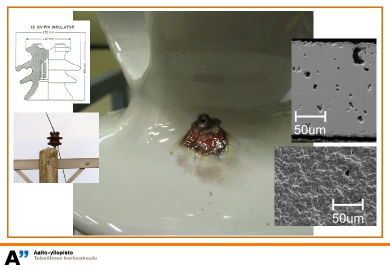
OVERHEAD LINE COMPONENTS 170 Pin Insulator (porcelain) 146 Æ162 Disk Insulator, Cap and Pin Insulator (glass or porcelain) Æ254 Line Post Insulator (porcelain) Cast Plastic Insulators Long-Rod Insulator Composite Insulator
GLASS INSULATORS • Toughened glass Improved mechanical strength Smaller size • Microscopic fractures on glass surface during manufacturing Shattering caused by mechanical impact or erosion (surface impurities) CERAMIC INSULATORS • Typically porcelain Weaker mechanical and electrical strength compared to toughened glass. Different constituents in porcelain have different thermal expansion at varying temperatures • No shattering and easier to manufacture large insulators
Insulator String • Capacitance chain with highly non-linear voltage distribution • Each individual unit has: self capacitance Δcs capacitance to ground Δce capacitance to conductor Δcv U 0 Δce Δcs Δcv Δcs l i = e (earth) or v (voltage conductor) x l = length of insulator string Δx = insulator unit length
Voltage distribution depends on capacitance ratio Cv/Ce > 1 voltage stress concentrates on tower beam side Cv/Ce = 1 voltage distribution is symmetrically Cv/Ce < 1 voltage stress concentrates on conductor side Beam (GND) 0 5 N=7 10 15 20 N = 15, 20 n 0 5 10 N=7 U [p. u. ] 0. 5 20 N = 15 N = 22 n = unit number Cv/Ce =1. 3 1. 0 n N = number of units 0. 5 Cv/Ce ≈ 0 Conductor 1. 0 15
GND Emax = 4. 6 k. V/mm U GND Emax = 3. 75 k. V/mm U GND U Emax = 4. 5 k. V/mm
COMPOSITE INSULATORS Manufactured from at least two different insulating materials insulator overhead strings, as separators phase lines in Used and • external insulation for surge arresters, bushings, transformers + mechanical strength + light weight + elastic (hard to vandalize) – cost – uncertain long term stability Protect core from moisture/chemicals/UV radiation/surface discharge • PD can release hydrogen which forms acid when combined with moisture leading to fracture
CABLE INSULATION Cable Termination Cable Joint AC: plastic – PVC, PE, XLPE (PEX) DC: HVDC transmission (> 150 k. V) with oil-paper insulation plastic – polarization state does not change fast enough when polarity is changed or voltage transients are applied to the cable critical field strength is exceeded – breakdown.
PAPER INSULATION (IN CABLES) 10 – 50 mm wide paper tape wrapped around the conductor with small gaps left between adjacent tapes • next layer is positioned to avoid continuous radial layering • the positioning of the tape is called registration and describes how much the layers are on top of each other 50% registration 75% registration Inhomogeneous construction: paper enables formation of thin, high dielectric strength oil sheet layers and prevents impurities from traveling between layers defines mechanical properties – cannot bend cable so that the layers connect
CABLE DESIGN 1. stranded conductor 2. conductor screen 3. insulation CONDUCTOR STRANDS • Water blocking powder can be used between the strands to prevent water migration. BASIC LAYERS (2 – 4) • 4. insulation screen Standard in most cables. ADDITIONAL LAYERS (5 – 10) 5. metallic screen • Vary depending on cable type and intended application • E. g. submarine, underground, etc. 6. bedding GROUNDED COMPONENTS (5, 7, 9) 7. metallic sheath 8. seperation sheath 9. armouring 10. outer sheath • Serves multiple purposes • E. g. protection against short circuit currents, external fields, mechanical stress, and moisture. BEDDING (6) • Used for cushioning and water blocking. SEPARATION SHEATH (8) • Can be implemented to separate different metallic layers. THE OUTER SHEATH (10) • Serves as external protection.
Small cavities and impurities are unavoidable in the cable Screens (semiconducting layers) are placed between the conductor and insulation layer and also between the insulation layer and the sheath. 1. 2. conductor/insulation – conductor screen (conductor cover) insulation/sheath – insulation screen (corona shield) 1. 2. Screens help to maintain the cylindrical symmetry of the field
CABLE JOINTS CONICAL CONSTRUCTION Should be logarithmic but straight conical is satisfactory • Some cables have premolded joints – insulation does not need to be altered • No voids or impurities router Er a r Ds a Dx rinner Et Dr insulation conductor x
CABLE JOINTS
CABLE TERMINATIONS ground Local concentration of electric field occurs where a conducting electrode continues and the grounded electrode terminates conductor insulation Grading of the electric field is necessary (FI: kentänohjaus) grading is done by adding a stress cone on top of the cable insulation the stress cone has a conducting layer on its surface or in its interior aim is to maintain a small and constant field
a. ) no grading b. ) geometric grading c. ) refractive grading Permittivity-based grading (refractive stress control, ɛ control, or resistive and capacitive grading) • Coat electrode edges with appropriately shaped insulation having different permittivity than the surrounding insulation. • A high permittivity insulating cylinder can be fastened over the section of the cable that has been stripped of insulation. Capacitance grows between the edge of the metal sheath and the bare section of insulation. Forces the field in the surrounding air to be distributed fairly uniformly along the surface of the insulation. e. ) stress cone placed on top of cable insulation d. ) stress cone placed directly on conductor Conductive surface of stress cone displayed as darker bold line. gas/liquid insulation solid insulation (mechanical) stress cone (solid insulation) E E The design is inserted through a hollow core (porcelain) insulator in this figure.
CABLE TERMINATIONS
BUSHING (FEED-THROUGH INSULATOR) A live conductor is fed through a grounded enclosure To avoid electric field concentration: • • • Electrodes and insulation shape is considered Grading ring can be applied (kentänohjausrengas) Capacitive grading – field electrodes added 100% 75% 50% 75% 25% 50% 25% 0% 0% without grading capacitive grading Folio sheets inserted into insulation
Electropedia: The World’s Online Electrotechnical Vocabulary www. electropedia. org switching device switchgear a device designed to make or break the current in one or more electric circuits general a term covering switching devices and their combination with associated control, measuring, protective and regulating equipment, also assemblies of such devices and equipment with associated interconnections, accessories, enclosures and supporting structures, intended in principle for use in connection with generation, transmission, distribution and conversion of electric energy hanical (mechanical) a switch conditions which may include specified operating overload conditions and also carrying for a specified time currents under specified abnormal circuit conditions such as those of short circuit. Note – A switch may be capable of making but not breaking short-circuit currents. disconnector (isolator)mechanical a switching device which provides, in the open position, an isolating distance in accordance with specified requirements. Note – A disconnector is capable of opening and closing a circuit only when either negligible current is broken or made, or when no significant change in the voltage across the terminals of each of the poles of the disconnector occurs. It is also capable of carrying currents under normal circuit conditions and carrying for a specified time currents under abnormal conditions such as those of short circuit-breaker conditions and also making, carrying for a specified time and breaking currents under specified abnormal circuit conditions such as those of short circuit. instrument transformer information transmit ameasuring intended antosignal to instruments, meters and protective or control devices Note – The term "instrument transformer" encompasses both current transformers and voltage transformers.
SUMMARY Breakdown in Liquid Insulation Breakdown in Solid Insulation Electrical Breakdown Intrinsic Breakdown Partial Discharge Electrical Treeing Electromechanical Breakdown Thermal Breakdown Electrolytic Breakdown Practical Insulators