GMEE 329 Optimisation Logique Bruno Rouzeyre Context The

GMEE 329 Optimisation Logique Bruno Rouzeyre

Context

The sub-space abstraction domain The sub-space abstraction domain is particularly meaningful to represent design descriptions

Abstraction levels system RT logic device behavior structure physic Representation domains

Abstraction levels The desired degree of details system RT The set of particular aspects of interest logic device behavior structure physic Representation domains

Abstraction levels system RT logic device behavior structure physic Representation domains

Abstraction levels It describes the behavior of the system, in terms of Input/Output relationships system RT logic device behavior structure physic Representation domains

Abstraction levels system RT logic device behavior structure physic Representation domains
 of the system, in terms")
It describes the structure (i. e. , the topology) of the system, in terms of a set of blocks, properly interconnected Abstraction levels system RT logic device behavior structure physic Representation domains

Abstraction levels The description is technology independent system RT It describes the structure (i. e. , the topology) of the system, in terms of a set of blocks, properly interconnected logic device behavior structure physic Representation domains

Abstraction levels system RT logic device behavior structure physic Representation domains

Abstraction It describes levels the physical structure of the system, in terms of elementary components. system They are used to implement the blocks defined in the RT structural domain logic device behavior structure physic Representation domains

Abstraction It describes levels the physical structure of the system, in terms of elementary components. system They are used to implement the blocks defined in the RT structural domain The description is technology dependent logic device behavior structure physic Representation domains

Relevant Operations • Each point in the abstraction-domain sub-space corresponds to a specific design description • Each design step corresponds to a movement from one point to another in the design space • Some movements correspond to particularly significant design steps.

Abstraction levels Synthesis Representation domains

Abstraction levels Analysis Representation domains

Abstraction levels Minimization Representation domains

Note • The “device” abstraction level is out of the scope of the present course and it will be thus no further considered

Outline • • • Geometric interpretation of Boolean Algebras Values taken by functions How representing functions? From functions to circuits Remarks Lessons learned

Geometric interpretation • The carrier Bn of a Boolean Algebra can be seen as an n-dimensional space, where each generic element v Bn (usually called a vertex), is represented by a vector of n coordinates, each B.

1 -input functions • B = { 0, 1} • B • F = F (x) 0 1 x

2 -input functions z B = { 0, 1} B 2 01 00 11 10 F = F (x, z) x

3 -input functions B = { 0, 1} z 011 B 3 111 F = F (x, y, z) 001 101 y 010 000 110 100 x

4 -input functions B = { 0, 1 } z B 4 F = F (x, y, z, w) w y x

Values taken by functions In general, in each vertex V, a function may: get the value 0 get the value 1 be not specified V off-set V on-set V don’t-care set

Values taken by functions In general, in each vertex V, a function may: get the value 0 get the value 1 be not specified V off-set V on-set V don’t-care set Typically used to represent combinations of input variables not relevant in a given design

z 011 111 0 001 y 101 010 000 1 110 100 x

Completely vs. incompletely specified functions A function f is completely specified iff dcs ( f ) = f is incompletely specified otherwise.

Completely specified function ons ofs Incompletely specified function ons dcs ofs

Note • For sake of simplicity, without loosing generality, in the sequel of the lecture we shall use, as a case study, the following completely specified 3 -input function F = F (x, y, z) :

How representing functions? • We need a way “to represent” or “to express” the value that the function F gets in each vertex, i. e. , in each point of its domain.

An intuitive approach • We could, for instance, deciding of expressing only the vertices in which the function gets the value 1:

An intuitive approach • We could, for instance, deciding of expressing only the vertices in which the function gets the value 1:
 and (y=0) and")
• We could write: F = 1 when ( (x=0) and (y=0) and (z=0) ) or ( (x=1) and (y=1) and (z=0) ) or ( (x=0) and (y=1) and (z=0) ) or ( (x=1) and (y=1) and (z=1) ).
 → x (x=0) → x’ and → · →")
Let’s try to simplify (x=1) → x (x=0) → x’ and → · → or → +
 → x (x=0) → x’ and → · →")
Let’s try to simplify (x=1) → x (x=0) → x’ and → · → or → + F = 1 when F= ( (x=0) and (y=0) and (z=0) ) or x’y’z’ + ( (x=1) and (y=0) and (z=0) ) or ( (x=1) and (y=1) and (z=0) ) or → x y’z’ + x y z’ + ( (x=0) and (y=1) and (z=0) ) or x’y z’ + ( (x=1) and (y=1) and (z=1) ) xyz

A further step Instead of representing separately the 4 vertices we could represent the whole “face”
 we could represent")
A further step Instead of representing separately the 4 vertices (z=0) we could represent the whole “face”

A further step Instead of representing separately the 4 vertices z’ we could represent the whole “face”

A further step. . . and instead of representing separately the 2 vertices we could represent the related “edge”
")
A further step. . . and instead of representing separately the 2 vertices (x=1) and (y=1) we could represent the related “edge”

A further step. . . and instead of representing separately the 2 vertices xy we could represent the related “edge”

Thus obtaining F= x’y’z’ + x y z’ + x’y z’ + x y z. → F = z’ + x y
 The library binding of sp expressions is trivial:")
From functions to circuits (Library binding) The library binding of sp expressions is trivial: logic operation sum logic gate or product and complement not

Example U = A’B’ + AD

Example U = A’B’ + AD U

Example U = A’B’ + AD U A D

Example U = A’B’ + AD A’ B’ A D U

Example U = A’B’ + AD A B A D The above is called multi-level networks U

Alternative implementation The above presented approach always leads to circuits implemented as 2 -level networks: or
 ET Entrées OU Sorties")
Alternative implementation Fonction implantée sur 2 niveaux (PLA, ROM) ET Entrées OU Sorties
’=a’. b’")
Alternative implementation Plan OU Plan ET + + F 1 F 2 (a+b)’=a’. b’ + (a+c’)’=a’. c + + (a’+b’)’=a. b + (b’+c’)’=b. c a a’ b b’ c c’ F 1 = a’. b’ + b. c + a. b F 2 = a’. c

Alternative implementation • In order to use different gates or to get different circuit “shapes”, algebraic transformations on the obtained logic expressions have to be performed. (Technology dependent Synthesis)

Remarks 1. In the expression: F = x’y’z’ + x y z’ + x’y z’ + x y z the function is expressed resorting to the set of its vertices called “minterms”

Remarks 2. In the expression: F = z’ + x y the function is expressed resorting to the set of its composing “sub-cubes” (or “k-cubes”).

Remarks 3. One could derive the expression: F = z’ + x y from the expression: F = x’y’z’ + x y z’ + x’y z’ + x y z applying the boolean algebra theorems (not presented here)
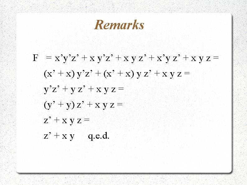

Remarks 4. The expression: F = z’ + x y is a minimal form of the expression: F = x’y’z’ + x y z’ + x’y z’ + x y z

Remarks 5. The 2 expressions: F = z’ + x y and: F = x’y’z’ + x y z’ + x’y z’ + x y z are “equivalent”, since they represent the same function.

Practical implication If we use logic gates to implement the function F = z’ + x y we obtain: z x y F

Practical implication If we use logic gates to implement the equivalent function F = x’y’z’ + x y z’ + x’y z’ + x y z we obtain:

x y z F= x’y’z’ + x y z’ + x’y z’ + xyz x y z F

Lessons learned 1. Concept of “cost ” • The “cost” of an implementation is proportional to the “cost” of the expression to be implemented • Minimizing expressions implies minimizing the implementation cost.

Lessons learned 2. Concept of “K-cubes” • Some practical sets of vertices play key roles: expressing function resorting to k-cubes can help to provide minimal cost implementations.

Lessons learned 3. Cost in Multi-Level Networks: • • Nombre de monômes Nombre de littéraux => Factorisation. Fonction
- Slides: 65