EC 6602 ANTENNAS AND WAVE PROPAGATION Mrs P


: T 1: John D Kraus, ” Antennas for all Applications”,")


: It is the basic short")


 Directive gain")

 The field pattern in (linear scale) typically represents a plot of the magnitude")


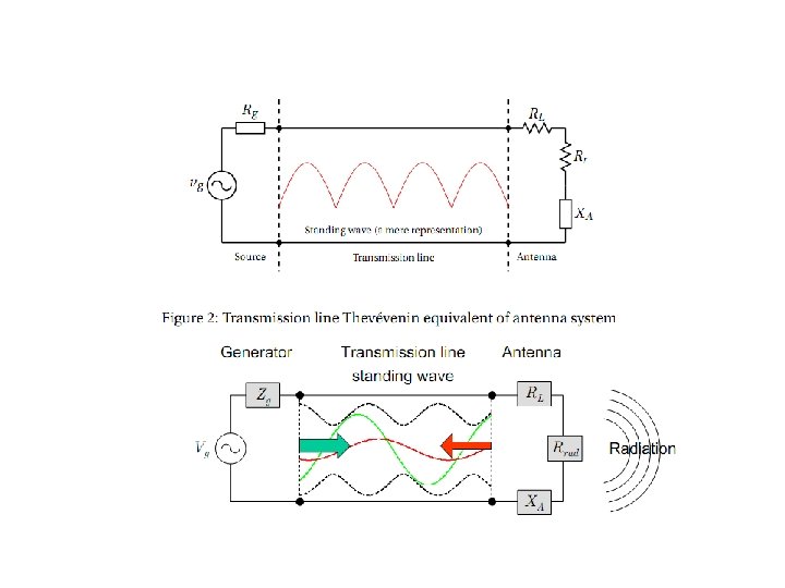
 reflections because of the mismatch between the transmission")
 is defined as “the")


- Slides: 93
EC 6602 -ANTENNAS AND WAVE PROPAGATION Mrs. P. Rajeswari
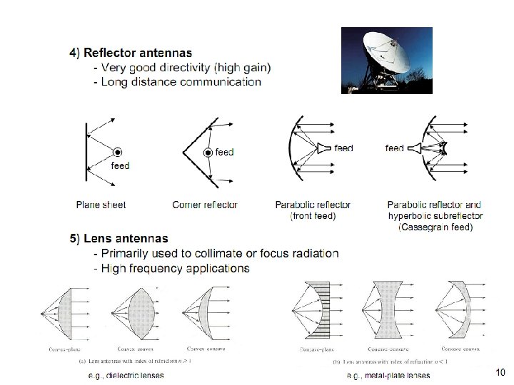
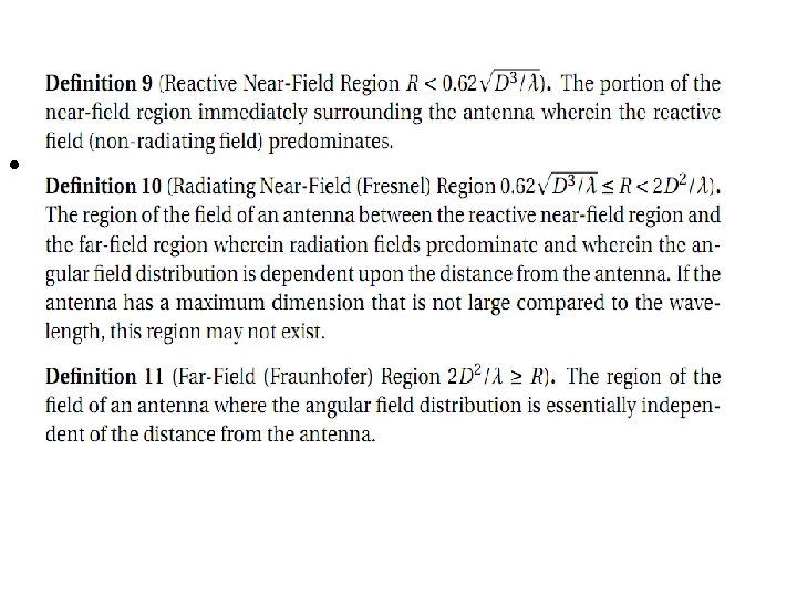
UNIT I ANTENNA FUNDAMENTALS • UNIT I FUNDAMENTALS OF RADIATION • Definition of antenna parameters – Gain, Directivity, Effective aperture, Radiation Resistance, Band width, Beam width, Input Impedance. Matching – Baluns, Polarization mismatch, Antenna noise temperature, Radiation from oscillating dipole, Half wave dipole. Folded dipole, Yagi array. • UNIT II APERTURE AND SLOT ANTENNAS Radiation from rectangular apertures, Uniform and Tapered aperture, Horn antenna , Reflector antenna , Aperture blockage , Feeding structures , Slot antennas , Microstrip antennas – Radiation mechanism – Application , Numerical tool for antenna analysis.
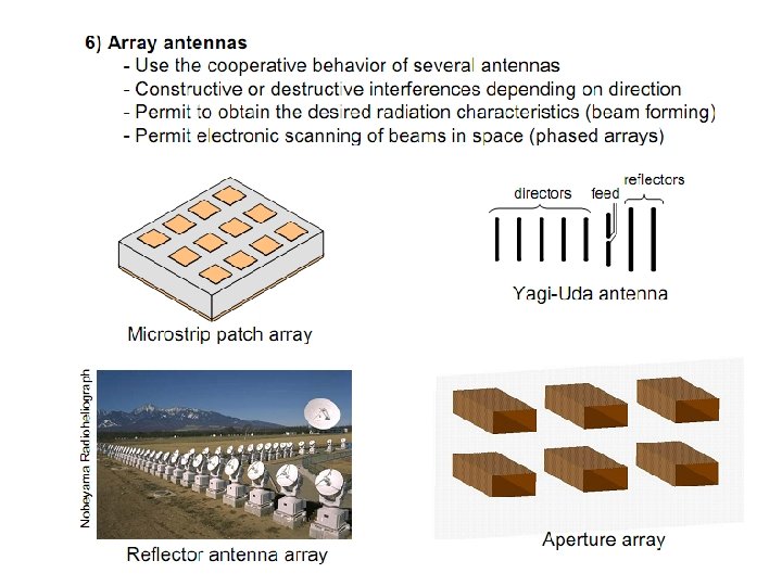
UNIT III ANTENNA ARRAYS N element linear array, Pattern multiplication, Broadside and End fire array – Concept of Phased arrays, Adaptive array, Basic principle of antenna Synthesis-Binomial array UNIT IV SPECIAL ANTENNAS Principle of frequency independent antennas –Spiral antenna, Helical antenna, Log periodic. Modern antennas- Reconfigurable antenna, Active antenna, Dielectric antennas, Electronic band gap structure and applications, Antenna Measurements-Test Ranges, Measurement of Gain, Radiation pattern, Polarization, VSWR UNIT V PROPAGATION OF RADIO WAVES • Modes of propagation, Structure of atmosphere, Ground wave propagation, Tropospheric propagation, Duct propagation, Troposcatter propagation, Flat earth and Curved earth concept Sky wave propagation – Virtual height, critical frequency, Maximum usable frequency – Skip distance, Fading, Multi hop propagation •
• TEXT BOOK(S): T 1: John D Kraus, ” Antennas for all Applications”, 3 rd Edition, Mc Graw Hill, 2005. REFERENCES: R 1. Edward C. Jordan and Keith G. Balmain” Electromagnetic Waves and Radiating Systems” PHI, 2006 R 2. R. E. Collin, ”Antennas and Radiowave Propagation”, Mc Graw Hill 1985. R 3. Constantine. A. Balanis “Antenna Theory Analysis and Design”, Wiley Student Edition, 2006. R 4. Rajeswari Chatterjee, “Antenna Theory and Practice” Revised 2 nd Edition, New Age, 2006. R 5. S. Drabowitch, “Modern Antennas” Second Edition, Springer Publications, 2007. R 6. Robert S. Elliott “Antenna Theory and Design” Wiley Student Edition, 2006. R 7. H. Sizun “Radio Wave Propagation for Telecommunication Applications”, Springer Publications, 2007.
Course Objectives • To give insight of the radiation phenomena. • To give a thorough understanding of the radiation characteristics of different types of antennas • To create awareness about the different types of propagation of radio waves at different frequencies
Course Outcomes • CO 1: Discuss the basic concepts of radiation from a current element and antenna parameters CO 2: Design aperture antennas and slot antenna CO 3: Predict the Radiation Pattern of different antenna arrays CO 4: Design special antennas such as frequency independent and broadband antennas CO 5: Describe various propagation methods of radio waves. CO 6: Analyze the characteristics of different antennas using ADS Software (Content Beyond Syllabus)
BASIC COMMUNICATION SYSTEM
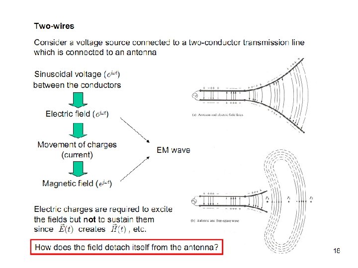
What is an Antenna? • An antenna is defined by webster’s Dictionary as “ a usually metallic device ( or a rod or wire) for radiating or receiving radio waves”. • The IEEE Standard Definition : The antenna or aerial as a “ ameans for radiating or receiving radio waves” • An antenna is a device for radiating and receiving radio waves. The antenna is the transitional structure between free-space and a guiding device
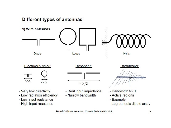
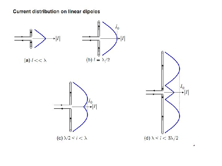
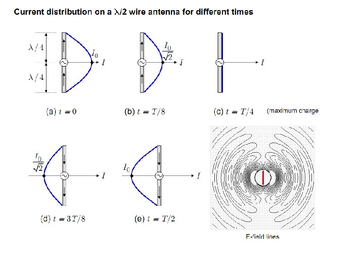
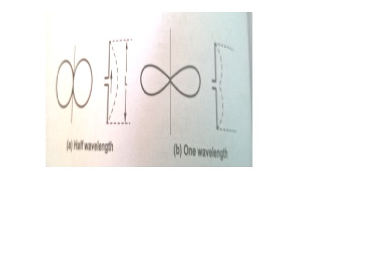
Basic Antenna Elements • Alternating current element( Hertzian dipole): It is the basic short linear antenna. It is assumed that the current along the length of linear antenna is constant. • Short dipole: It is a linear antenna with a length less than ʎ/4. The current distribution of short dipole is assumed to be triangular. • Short monopole: It is also a linear antenna with a length less than ʎ/8 with a current distribution assumed to be triangular. • Half wave dipole: It is a linear antenna with a length equal to ʎ/2. This antenna is generally a centerfed and its current distribution is sinusoidal. • Quarter wave monopole: It is a linear antenna with a length equal to ʎ/4. Such antenna is fed at one end with respect to ground or earth with sinusoidal current distribution.
Important Properties of Antenna • An antenna has identical impedance inspite of being used for transmitting or receiving purposes. This property is called equality of impedances. • An antenna exhibits identical directional characteristics and patters whether it is used for transmitting or receiving purposes. This property is known as equality of directional patterns. • An antenna has same effective length inspite of being used for transmitting or receiving purposes. This property is called equality of effective lengths. • All the three properties mentioned above can be verified using Reciprocity theorem for antenna.
Functions of antenna • • • Antenna acts as a transducer. It converts electrical energy into an electromagnetic energy at the transmitting end, while it converts an electromagnetic energy back into the form of an electrical energy at the receiving end of the communication link. Antenna acts as an impedance matching device. At the transmitting end, it matches the impedances between transmitter and free space while at receiving end, it matches the impedance between the free space and receiver. Hence antenna functions as a coupler between transmitter, free space and receiver. Antenna functions as a device which can direct radiated energy is most desired direction suppressing energy in undesired directions. Antenna acts as traditional structure at the region where transition between guided wave and free space wave and vice versa. It functions as remote sensing temperature measuring device.
Antenna as a transitional Device
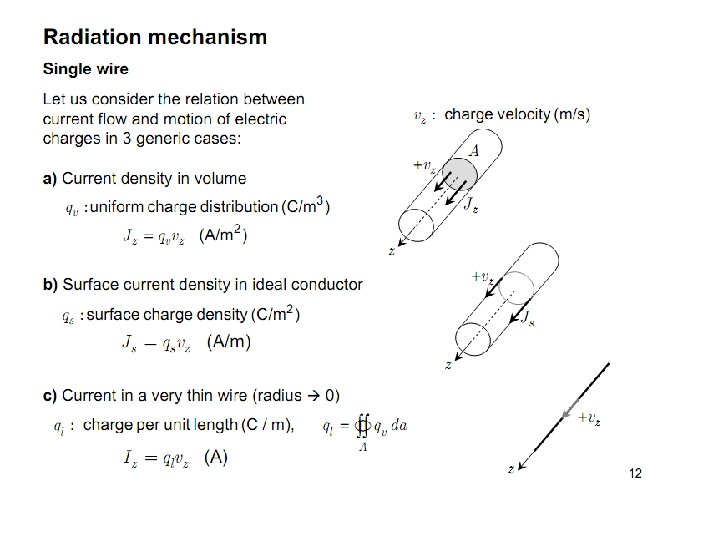
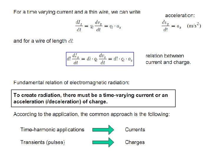
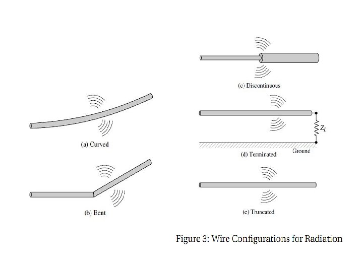
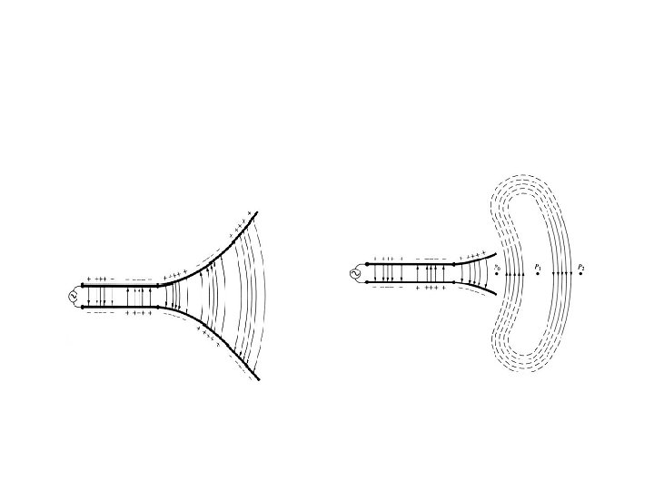
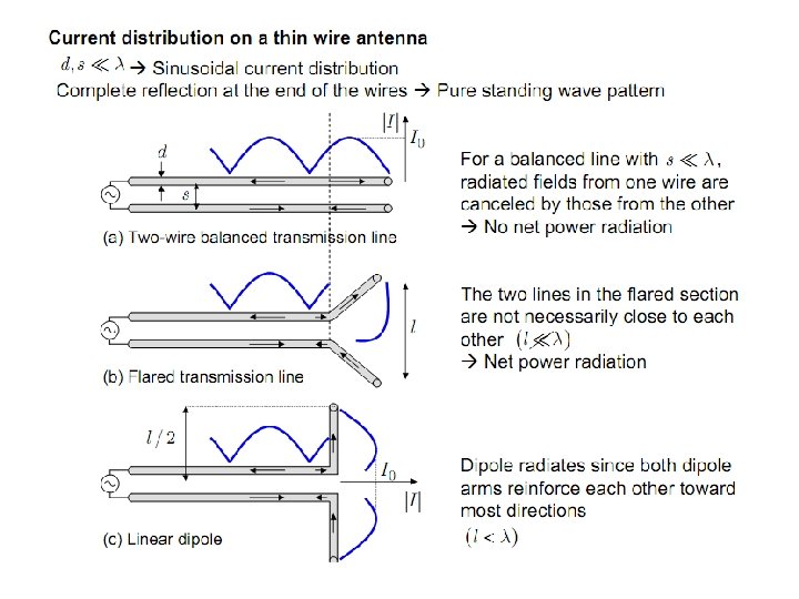
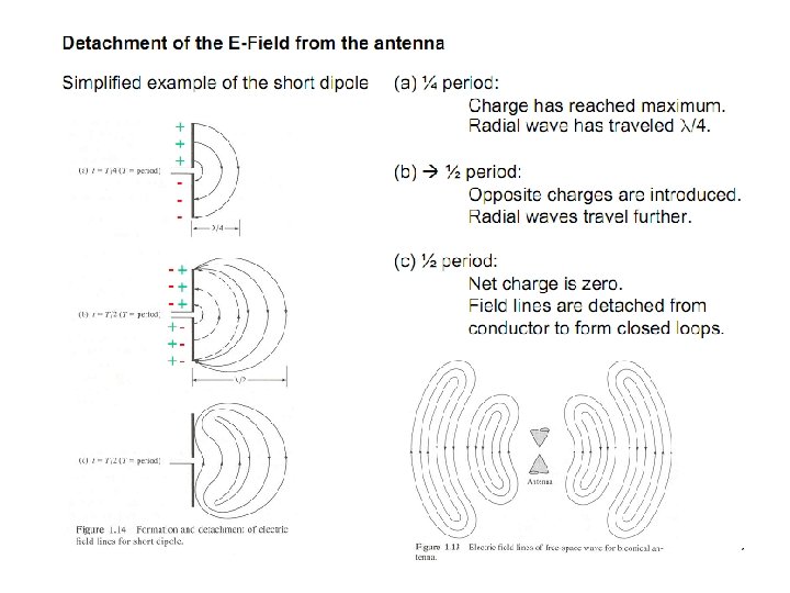
Radiation from dipole
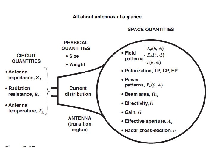
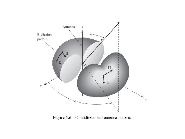
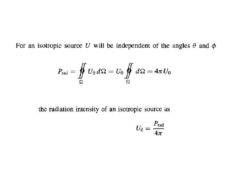
Antenna parameters • To describe the performance of an antenna An isotropic radiator is defined as “ a hypothetical lossless antenna having equal radiation in all directions.
• • • Radiation Intensity Radiation Pattern (Field pattern, power pattern) Directive gain and Directivity Power gain Antenna bandwidth, antenna beamwidth Effective length Antenna input impedance Effective aperture Antenna Temperature Antenna polarization
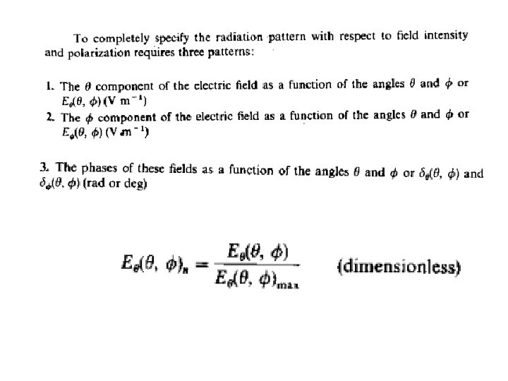
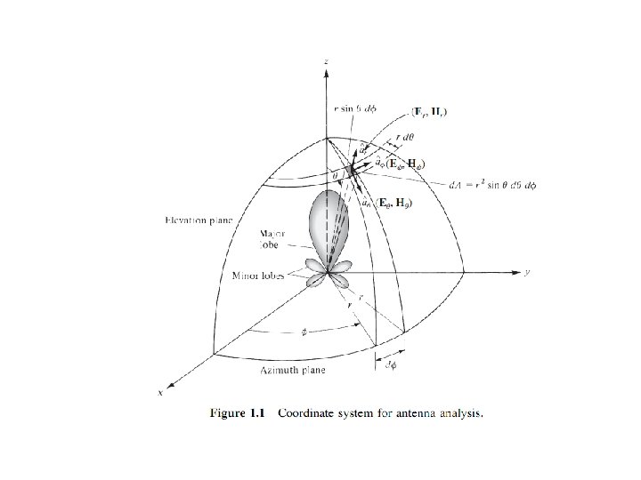
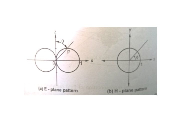
Radiation Pattern An antenna radiation pattern or antenna pattern is defined as “a mathematical function or a graphical representation of the radiation properties of the antenna as a function of space coordinates. Radiation properties include power flux density, radiation intensity, field strength, directivity, phase, or polarization. ”
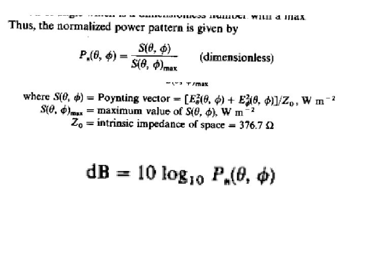
(1) The field pattern in (linear scale) typically represents a plot of the magnitude of the electric or magnetic field as a function of the angular space (2) The power pattern in (linear scale) typically represents a plot of the square of the magnitude of the electric or magnetic field as a function of the angular space; and (3) The power pattern in (d. B) represents the magnitude of he electric or magnetic field, in decibels, as a function of the angular space. E Plane pattern is defined as “ the plane containing electric field vector and the direction of maximum radiation.
Field Patterns
Power Pattern
Radiation Pattern Lobes
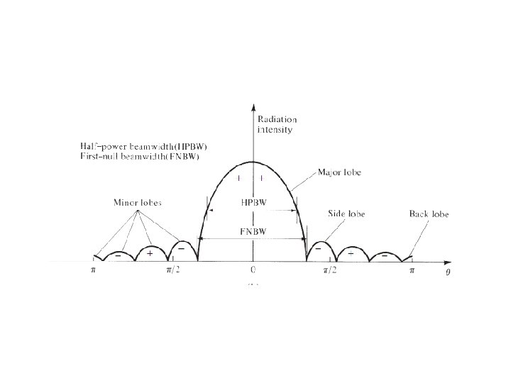
Radiation Pattern Lobes • A radiation lobe is a “portion of the radiation pattern bounded by regions of relatively weak radiation intensity. ” A major lobe (also called main beam) is defined as “the radiation lobe containing the direction of maximum radiation. ” A minor lobe is any lobe except a major lobe. A side lobe is “a radiation lobe in any direction other than the intended lobe. ” A back lobe is “a radiation lobe whose axis makes an angle of approximately 180◦ with respect to the beam of an antenna. ”
Principal E and H plane patterns of Horn antenna
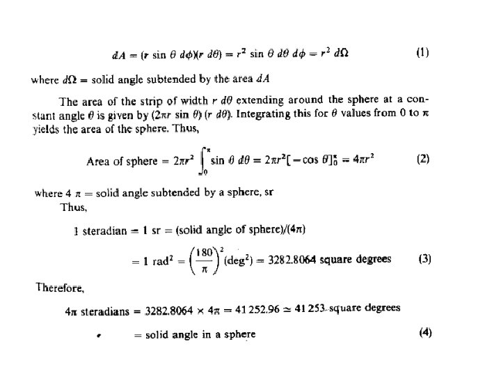
Radian and Steradian
• One radian is defined as the plane angle with its vertex at the center of a circle of radius r that is subtended by an arc whose length is the radius r. The measure of a solid angle is a steradian. One steradian is defined as the solid angle with its vertex at the center of a sphere of radius r that is subtended by a spherical rface area equal to that of a square with each side of length r.
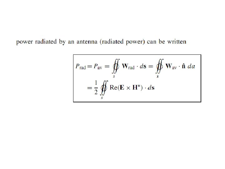
Radiation Power Density The quantity used to describe the power associated with an electromagnetic wave is the instantaneous Poynting vector
The Poynting vector is a power density, the total power crossing a closed surface n be obtained by integrating the normal component of the Poynting vector over the ntire surface. In equation form
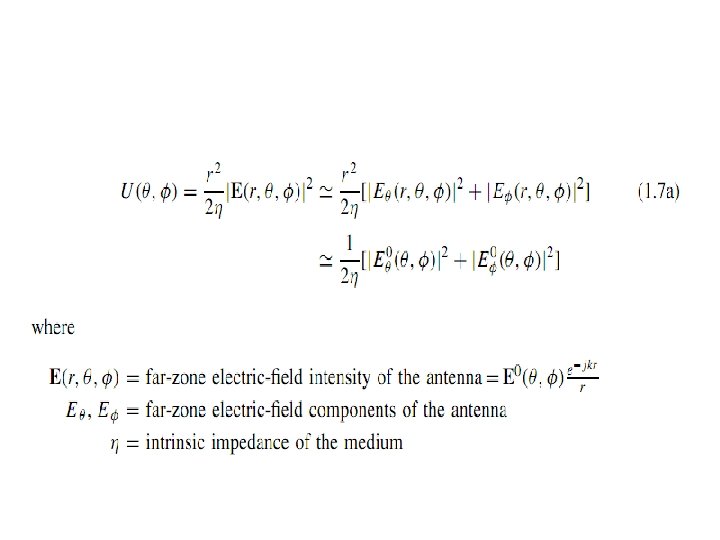
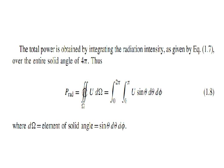
Radiation Intensity
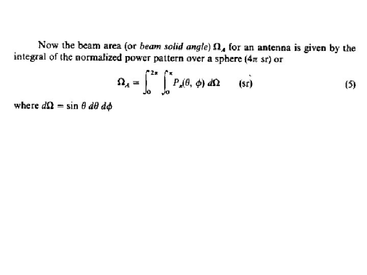
Beam Efficiency
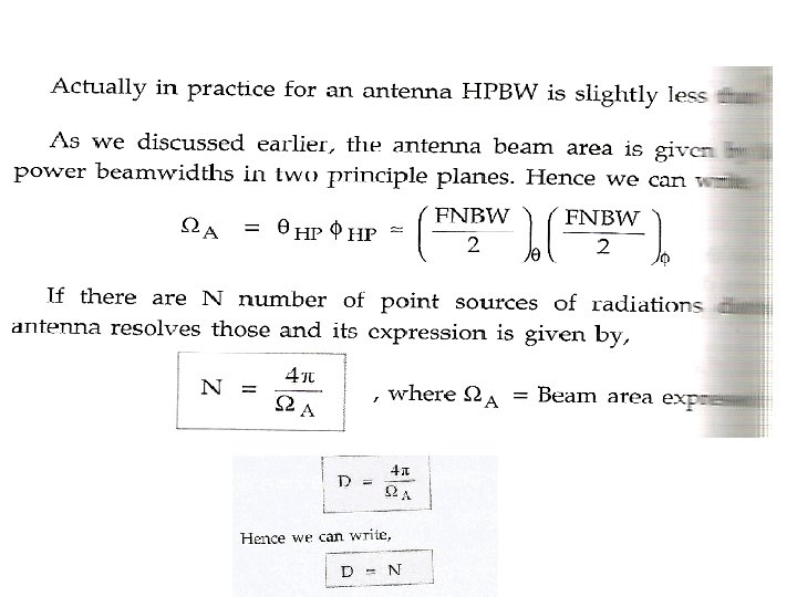
Beamwidth • The beamwidth of a pattern is defined as the angular separation between two identical points on opposite sides of the pattern maximum. • half-power beamwidth (HPBW), which is defined by IEEE as: “In a plane containing the direction of the maximum of a beam, the angle between the two directions in which the radiation intensity is one-half value of the beam. ”
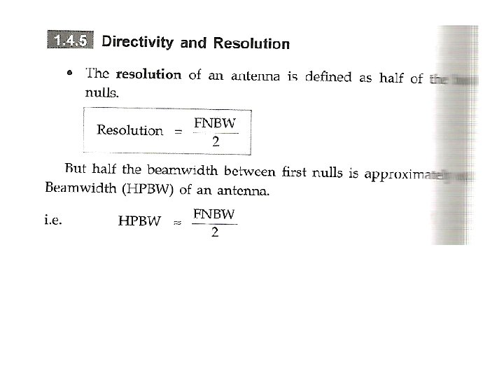
BEAMWIDTH IS THE ANGULAR SEPARATION BETWEEN THE FIRST NULLS OF THE PATTERN, AND IT IS REFERRED TO AS THE FIRSTNULL BEAMWIDTH (FNBW).
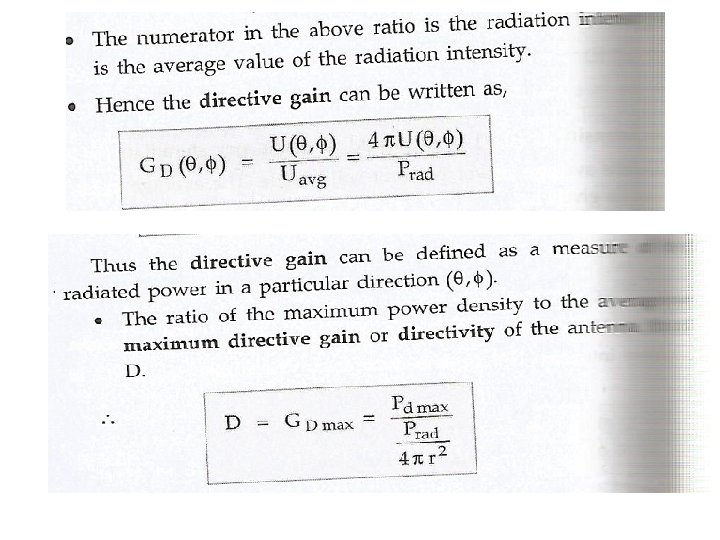
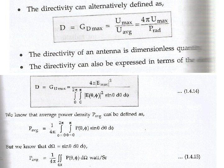
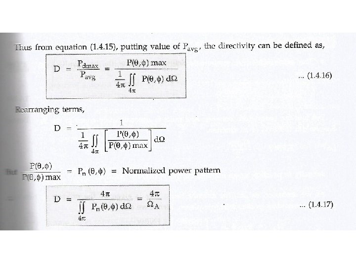
Directive Gain
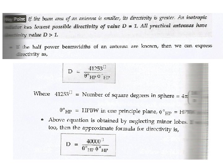
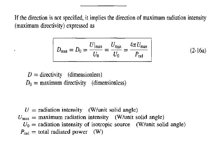
Directivity
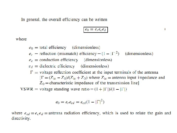
ANTENNA EFFICIENCY Losses due to (1) reflections because of the mismatch between the transmission line and the antenna and 2. I 2 R losses (conduction and dielectric).
Gain • Gain of an antenna (in a given direction) is defined as “the ratio of the intensity, in a given direction, to the radiation intensity that would be obtained if the power accepted by the antenna were radiated isotropically.
Beam Efficiency
The bandwidth of an antenna is defined as “the range of frequencies within which the performance of the antenna, with respect to some characteristic, conforms to a specified standard. ”
Polarization
Linear Polarization
Circular polarization
Elliptical Polarization • A time-harmonic wave iselliptically polarized if the tip of the field vector (electric or magn The necessary and sufficient conditions • The field must have two orthogonal linear components • The two components can be of the same or different magnitude etic) traces an elliptical locus in space.
Input impedance • Input impedance is defined as “the impedance presented by an antenna at its terminals or the ratio of the voltage to current at a pair of terminals or the ratio of the appropriate components of the electric to magnetic fields at a point. ”
Antenna Radiation Efficiency
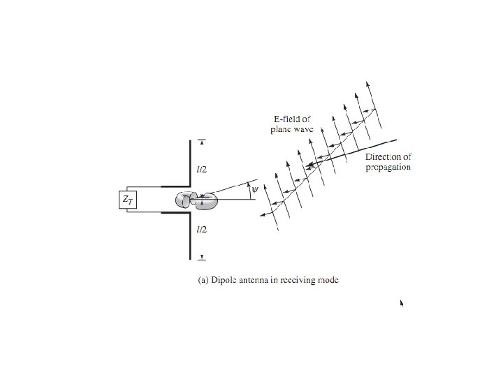
The effective length of an antenna, whether it be a linear or an aperture antenna, is a quantity that is used to determine the voltage induced on the open-circuit terminals the antenna when a wave impinges on it.
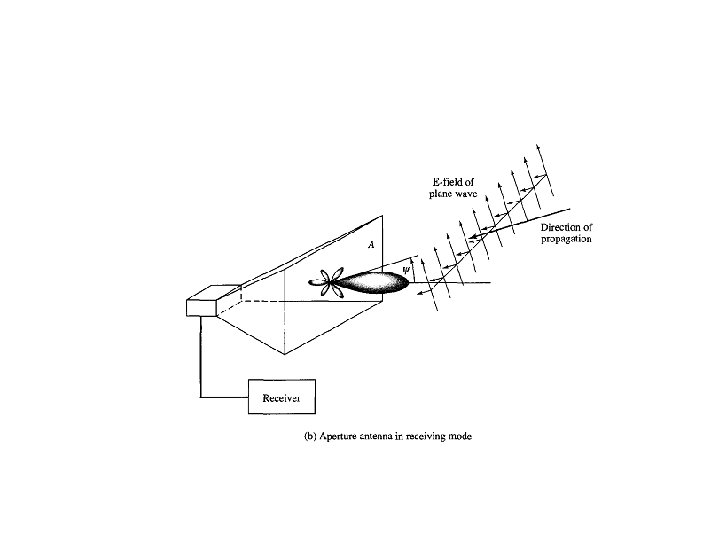
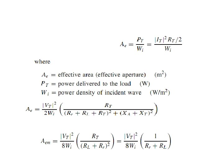
Effective Aperture • is defined as “the ratio of the available power at the terminals of a receiving antenna to the power flux density of a plane wave incident on the antenna from that direction, the wave being polarization-matched to the antenna.
Maximum Effective Aperture
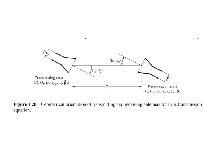
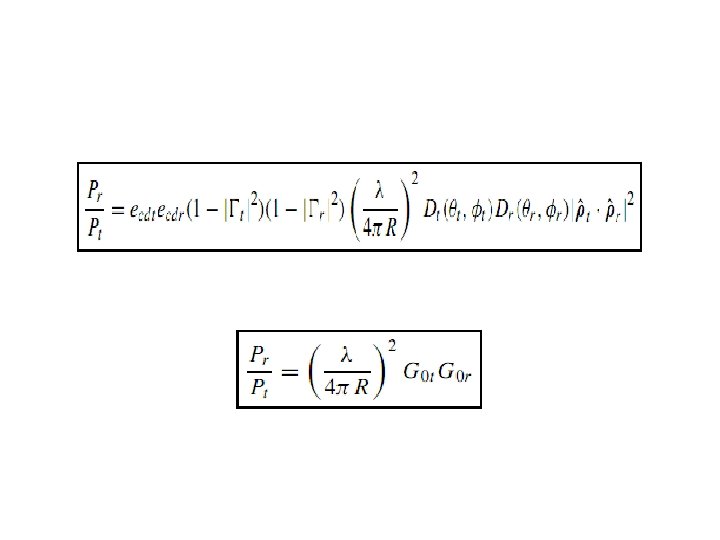
Friis transmission equation
FBR • Front to Back ratio is defined as the power radiated in the desired direction to the power radiated in the opposite direction • Depends on frequency, electrical length and spacing