Compaction and Quality Control of Earthwork Compaction Process


/ MDD(Maximum Dry Density) values for soil/blanket are determined")
 Compacting effort § (b) Moisture control §")
 Compacting Effort: • In modern construction projects, heavy compaction machinery are deployed to")
 • Sheep Foot Roller or Pneumatic Roller provides")
 Moisture Control Maximum density with minimum compacting effort can be achieved by compaction")
 Thickness of Layer • Depends upon type of soil involved and type of")


 § Available in weight of 3. 4")


 content % 225 2.")


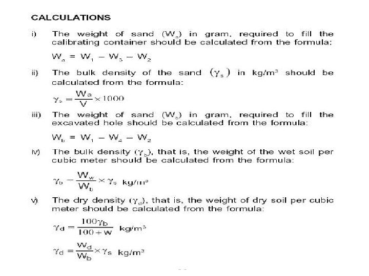
 = Mass/Volume= M/V kg/m³ Where, M= Mass of wet")


 Weight of sand in the cone of the")
 B. Determination of bulk density of sand (γs) § Determine internal volume")
 C. Measurement of Soil Density § Expose the area to be tested")


- Slides: 59
Compaction and Quality Control of Earthwork
Compaction • Process of increasing “Density of Soil” by mechanical means, by packing the soil particles closer together (by expelling air from the voids). • To produce a soil mass with controlled or improved engineering properties. • The water acts as lubricant and a closer packing of soil grains is obtained by the expulsion of air from the voids.
Soil Mass Structure Voids Ratio e = Vv/Vs Porosity % n= Vv/Vt Water Content % w = Ww/Ws Bulk Density γ=W/Vt Dry Density γd = Ws/Vt = γ/(1+w) Degree of Saturation % S= Vw/Vv
Compaction results in: • Reduction of air voids • A Homogeneous soil mass having improved soil properties such as Ø Increase in Shear strength, Ø Decrease in Compressibility (Settlement) & Ø Decrease in Permeability.
Advantages of Compaction § Helps soil to acquire increase in strength, in both bearing resistance and shear strength. § Reduces compressibility, thus minimising uneven settlement during service. § Increases density and reduces permeability, thereby reducing susceptibility to change in moisture content. § Reduces erodability. § Results in homogenous uniform soil mass of known properties.
Limitations of Compaction Ø Excessive creep or slipping of slopes. Ø Swelling and shrinkage characteristic of soils due to variation in moisture content because physio-chemical properties of a soil do not change on compaction. Ø Settlements due to consolidation of bank and subsoil that can occur even for a few years after construction of the bank.
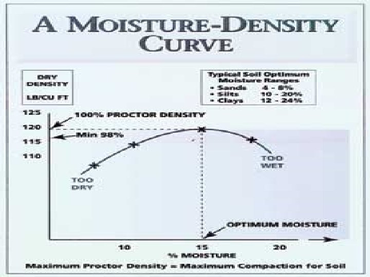
• OMC (Optimum Moisture Content)/ MDD(Maximum Dry Density) values for soil/blanket are determined in Lab by “Proctor Compaction Test Equipment”. • These values are used for computation of degree of compaction of earthwork in field. • The fill materials used at site for embankment construction should have Moisture Content near its OMC. • For soil/blanket to be used for construction of embankment contains with Fines <5%, Relative Density (RD) Tests are conducted in Lab for determining density (γmax & γmin). • These γmax & γmin values are computing Degree of Compaction. used for
Factors affecting Compaction in Field § (a) Compacting effort § (b) Moisture control § (c) Soil type § (d) Thickness of layer § (e) Number of passes § (f) Compaction equipments
(a) Compacting Effort: • In modern construction projects, heavy compaction machinery are deployed to provide compaction energy. • Types of machinery required are decided based on type of soil to be compacted. • The method of compaction is primarily of four types: • Static compaction, • Dynamic or Impact compaction • Vibratory compaction and, • Kneading compaction.
For Cohesive soils (Clays & Silts) • Sheep Foot Roller or Pneumatic Roller provides the kneading action for breaking the clods of clayey soils. • Thickness of layer should not be more than depth of feet of roller plus 50 mm. • Pneumatic Roller or Smooth Wheel Roller is effective for compaction of Silty soils. For Cohesion-less Soils (Sandy and Gravelly soil) • Vibratory Rollers is most effective. • Smooth Wheel and Pneumatic Roller can be used if granular soils have some fines.
(b) Moisture Control Maximum density with minimum compacting effort can be achieved by compaction of soil near its OMC (Optimum Moisture Content). (c) Soil Type • Normally, clays and silts (fine grained soils) offer higher resistance to compaction. • Sandy soils or gravelly soils (coarse grained soils) are amenable for easy compaction. • Coarse grained soils yield higher densities in comparison to clay. • A well-graded soil (Cu > 4 & 1 < Cc < 3) can be compacted to higher density. Cu = D 60/D 10 and Cc = D 302/(D 60 x D 10)
(d) Thickness of Layer • Depends upon type of soil involved and type of roller, its weight and contact pressure of its drums. • Decided on the basis of Field Compaction Trials. Normally, 200 – 300 mm is optimum in field for achieving homogenous compaction. (e) Number of Roller Passes • Density of soil increases with the number of passes but after optimum number of passes, further increase in density is insignificant for additional number of passes. • Determined by Field Compaction Trials.
For Suitable type of Compaction Equipment, Number of Passes and Maximum thickness of Layers for different Type of Soils Refer to Annexure-4 of RDSO Guidelines GE: G-1 (July’ 2003)
Smooth Wheeled Rollers • Self-propelled or Towed, Weight 2 – 20 T. • Suitable for: Well Graded Sands and Gravels, Silts and Clays of low plasticity. • Unsuitable for: Uniform Sands, Silty Sands and Soft Clay.
Vibratory Roller • Range from “Hand guided” to “Larger roller”. • Suitable for: Most soils with low to moderate fines content. • Unsuitable for: Large volume of work and wet clayey soil. 17
Pneumatic Tyred Roller • Usually a container on two axles. • Wheels aligned to give a full-width rolled surface. • Dead loads added to give masses of 12 -40 T. • Suitable for: most coarse and fine grained soils. • Unsuitable for: very soft clay & highly variable soil.
Sheep Foot Roller • Also known as a 'tamping roller‘. • Self propelled or towed units, with hollow drum fitted with projecting club-shaped 'feet‘. • Weight: 5 -8 T. • Suitable for: fine grained soils/sands/gravels, with >20% fines. • Unsuitable for: very coarse soils & uniform gravels.
Impact Roller • Introduces energy to ground surface in succession, around two impacts per second. quick • By doing this in a rolling action at around 10 kmph, large areas can be treated quickly. • Useful for Bulk earthworks. Compacting in 1 m lifts up to 2 to 3 m depth at 10 kmph. 20
Grid Roller • Towed units with rolls of 30 -50 mm bars, with spaces between of 90 -100 mm. • Weight: 5 -12 T. • Suitable for: well-graded sands; stony soils with fine fractions. soft rocks; • Unsuitable for: uniform sands; silty sands; very soft clays.
Vibrating Plate for Slope Compaction § Range from “hand-guided” to “large machine”. § Suitable for: most soils with low to moderate fines content. § Unsuitable for: large volume work; wet clayey soils.
Slope Compactors (Working with Counter Balancing Method) § Available in weight of 3. 4 T to 9. 5 T § Vibration Frequency – 2000 rpm
Slope Vibratory Roller § Available in weight of 5. 5 T to 17. 0 T § Drum width: 900 to 1300 mm § Vibrations: 1300 to 2000 vib/min
Small Width Vibratory Roller developed by RDSO
Specifications of Small Width Roller S. N. 1. 2. 3. 4. 5. 6. 7. 8. Descriptions Specification Drum width 900 mm Drum Diameter 750 mm Drum thickness 20 -22 mm Overall width 1040 mm Overall length 2730 mm Overall height 2600 mm Operating Weight (Kgs) 3300 Maximum applied force Kgf per 5500 Drum 9. Front Axle Load (Kgs) 1800 10. Rear Axle Load (Kgs) 1500 11. Working Speed (kmph) 0 -10 12. Transport Speed (kmph) 0 -10
Field Compaction Trials Ø Why field compaction trial is required? - Compaction process in lab & field is not comparable. - For deciding most appropriate compactor. - For determination of attainable dry density with type of compactor available under various combinations of field parameters.
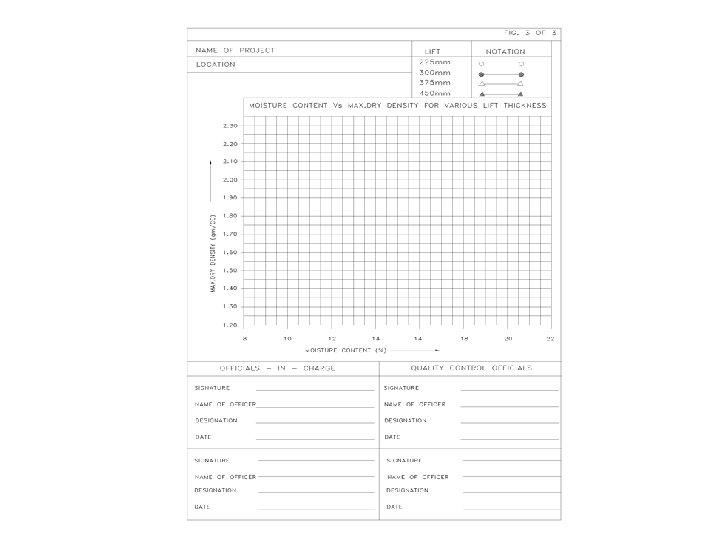
Procedure Thickness: 0. 15 m to 0. 55 m Moisture Content : OMC-4, OMC+4, PL-2 Thickness: 225 mm, 300 mm, 375 mm & 450 mm No. of observations: 6 (after 4, 6, 8, 10, 12 & 14 roller passes) § Total Observations = 4 x 4 x 6 = 96 § §
Computation Sheet S. No 1. Lift Moistur thickness e (mm) content % 225 2. 300 3. 375 4. 450 5. 525 6. 600 4 Computed by____________ Name _______________ Designation_____________ Date ___________ Dry density of soil (gm/cc) Nos. of the roller passes 6 8 10 12 14 16 Remarks 18 Checked by ________ Name___________ Designation_________ Date ___________
Use of Mixed Type of Soils § If different type of fill material are used, they should be deposited in such a way that all parts of site receive equal amount of given material in roughly the same sequence, to get homogeneous sub-grade. § If fill soil contains cobbles/boulders/rock/waste fragments, largest size of material should not be greater than 2/3 rd of the loose layer thickness. Large size creates hurdles during compaction. § Slope Stability Analysis to be carried out to ensure stability of such embankments, taking into account properties of all layers. § If materials of bigger size are only in small quantity, these may be placed on toe of the embankment instead of using as sub-grade material.
Over Compaction § Relative soil compaction test results over 100% do not necessarily mean over-compaction because the Relative Compaction is based on the Maximum Dry Density of the soil obtained by the Proctor Test and this does not refer to absolute Maximum Dry Density. § Over-compaction is not desirable as it may create cracks in the underlying compacted material. § Excessive compaction also poses risk of fracturing granular soils resulting in the reduction of soil strength parameters. § It causes waste manpower. of machine power and
Field Compaction Testing Methods Method of Procedure measurement of test Parameters to be measured Remarks Sand Replacement Method IS-2720 a) In-situ Dry May be adopted (Part 28) Density for all type of 1974 b) Moisture content soils Core Cutter Method IS-2720 (Part 29) 1975 -do- May be adopted for fine grained soils Nuclear As issued a) Bulk density May be used in Moisture by RDSO b) Moisture Content consultation with Density Gauge RDSO c) Dry density d) Degree of compaction
Important Expressions Bulk density (ρ) = Mass/Volume= M/V kg/m³ Where, M= Mass of wet soil & V= Volume of wet soil Dry Density (ρd) = ρ / (1+w) kg/m³ where w = water content of the soil Degree of Compaction (%) = (ρd Field/MDD Lab)x 100
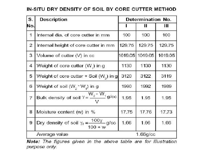
Core Cutter Method Apparatus § Cylindrical Core Cutter Size 129. 75 mm Long & 100 mm internal dia. § § § § Steel Rammer of 9 kg weight Steel Dolly Balance Steel Rule Spade or Pickaxe Straight edge Knife
Procedure § Measure “Height” and “Internal diameter” of core cutter. Apply grease to the inside of core cutter. § Weigh the empty core cutter (W 1). § Clean and level the place to be tested. § Drive the core cutter, with a steel dolly on its top, into the soil to its full depth with the help of a steel rammer. § Excavate the soil around the cutter with a crow bar and gently lift the cutter without disturbing the soil in it. § Trim the top and bottom surfaces of the sample and clean the outside surface of the cutter. § Weigh the core cutter with soil (W 2). § Remove soil from the core cutter and take representative soil sample from it to determine the moisture content.
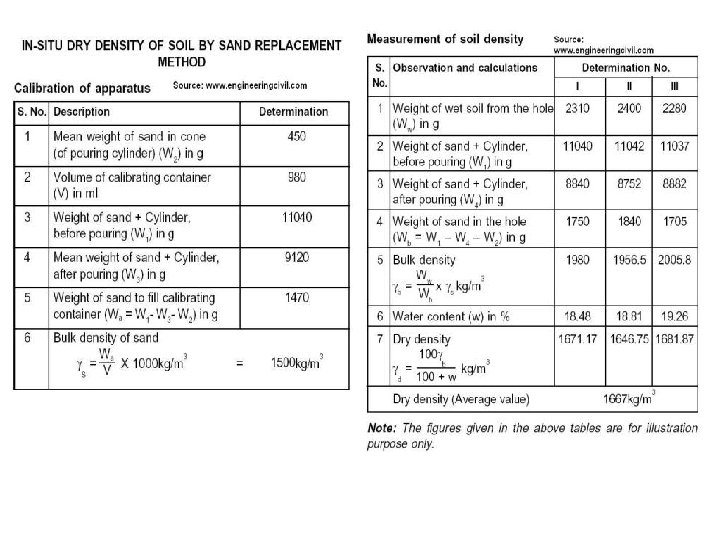
Sand Replacement Method Apparatus § Sand-pouring cylinder § Cylindrical container calibrating § Soil cutting and excavating tools such as a scraper tool, bent spoon. § Glass plate – 450 mm square and 9 mm thick or larger § Metal containers excavated soil to collect § Metal tray – 300 mm square and 40 mm deep with a 100 mm hole in the centre § Balance, with an accuracy of 1 g Clean, uniformly graded natural sand passing 1 mm and retained on 6 OO Micron Sieve.
Procedure A. Calibration of Apparatus (i) Weight of sand in the cone of the pouring cylinder § Fill the pouring cylinder so that the level of the sand is within about 10 mm of the top. § Total initial weight (W 1) to be maintained constant throughout the tests for which the calibration is used. § Place pouring cylinder on glass plate. Open shutter of the pouring cylinder and allow sand to run out. When no further movement of sand takes place, close the shutter and remove the cylinder carefully. § Collect the sand that had filled the cone of the cylinder (the sand left on glass plate) and weigh it. § Repeat the measurements thrice and take the mean weight (W 2).
Procedure (Contd…) B. Determination of bulk density of sand (γs) § Determine internal volume (V) of the calibrating container from the weight of water contained in the container when filled to the brim or by measuring internal dimensions of the container. § Place pouring cylinder on top of the calibrating container after being filled to the constant weight (W 1). § Open the shutter and allow sand to run out. When no further movement of sand takes place, close the shutter. § Remove the pouring cylinder and weigh it. Repeat the measurements at least thrice and take the mean weight (W 3).
Procedure (Contd…) C. Measurement of Soil Density § Expose the area to be tested and trim it to a level surface, using scraper tool. § Lay the metal tray with central hole on the prepared surface of the soil. Excavate hole in the ground, using the hole in the tray as guide, to depth of the layer to be tested or a maximum of 150 mm. § Collect the excavated soil and weigh it (Ww). Remove the metal tray. § Place the pouring cylinder, filled to the constant weight (W 1), on the hole concentrically. Open the shutter and allow sand to run out into hole. When no further movement of sand takes place, close the shutter. Remove the cylinder and weigh it (W 4). § Determine water content (w) of the excavated soil.
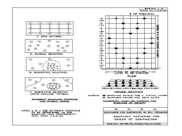
Nuclear Density Moisture Gauge § Dry Density has to be measured for every 500 m 2 surface area of compacted earth. A bank of 10 m height will typically need one test in every 10 - 11 m length. § In case of projects with large quantity of earthwork, carrying out these checks by conventional methods may cause hindrance in accelerated construction of embankment. § One of the alternative is to use Nuclear Gauges, which takes very less time, is non-destructive in nature and allows repetitive measurements at same test location.
§ Uses low level radiation to measure the “bulk/wet density” and “moisture content” of soil and granular construction materials. § In most of the gauges now-adays, both the parameters are measured by the same gauge. § The results are processed and displayed directly. § Data can machine. be stored in the § Being used world over for 20 -30 years. § Being used extensively by NHAI and AAI for certification of earthwork.
Apparatus § Gamma Ray Source & Detector for “density measurement”. § Neutron Source & Detector for “moisture measurement”. § Reference Standard – A block of material for checking instrument operation. Separate for each equipment.
Other equipments with Gauge § Site Preparation Device. § Drive Pin Guide. § Drive Pin Extractor. § Hammer.
Modes of Working Direct Transmission Mode § Up to 300 mm Depth. § Preferred mode, because of deeper zone of influence. § Can measure Density Only. § § Backscatter Mode Can measure both Density and Moisture Content. Less precise, as compared to Direct Transmission Mode.
Working Procedure for use of Nuclear Gauge For Western Corridor of DFC, RDSO has issued a Working Procedure, after site checks and study of provisions of International Standards. 1. Calibration of Gauge § By Accredited Agency or by the Manufacturer, as per ASTM D-6938 procedure. § To be done Initially and thereafter at periods not exceeding 12 Months. § If the tolerances prescribed cannot be met at any time, gauge to be re-calibrated. § Record to be maintained as per ASTM D-6938 and calibration to be ensured before using any Gauge.
2. Standardization of the Gauge § Daily before start of the work, by using Reference Block for that machine and in compliance with Procedure stipulated by the Manufacturer. § Records to be maintained. § To be repeated after 8 Hours of continuous use. § To be done with the Gauge located at least 9 m away from any other Nuclear Gauge and clear of large masses of water or other radioactive items. § If at any time during use, the measurements become suspect, another standardization check should be performed.
3. Procedure for Measurement § Keep all radioactive sources at least 9 m away. § Prepare/level the test site, by grading/scraping and using fine sand as filler material. § Make a hole of 50 mm dia using “Site Preparation Device”. Place the gauge and align it over the hole. § Lower the probe in the hole to the desired depth. § Read the measurements directly from the readout unit. § Retract the probe and ensure that radioactive source is safely housed. § Repeat the measurements, if needed.
Feedback received from Field § Measurement takes about 6 - 7 minutes as compared to about 20 – 30 minutes in Sand Replacement Method. § In Daily Verification Checks, the difference in degree of compaction obtained by Nuclear Gauge and Sand Replacement Method varies between 1 to 2. 36%. § More number of field density checks are being performed by using Nuclear Gauge, which would help in enhancing progress of earthwork.
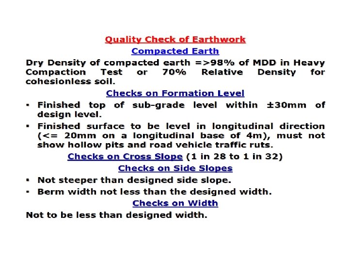
Quality Assurance of Earthwork
Minimum requirement of equipment and tests in field lab Gradation Analysis-Sieve and Hydrometer. Atterberg’s Limits - Liquid Limit & Plastic Limit. Optimum Moisture Content (OMC), Maximum Dry Density (MDD) and Relative Density. Placement moisture content & in-situ Density.

 Perform quality assurance
 Concepts of quality control
 Compaction control for compactors
 Rdso pit line drawing
 Cut and fill calculations grid method
 Mass diagram cut and fill example
 Rdso guidelines for earthwork
 Prismoidal formula for volume
 Gao cost estimating and assessment guide
 Quality management pmp
 Pmbok quality management
 Www.mbaknol.com
 Grandfather of tqm
 Product and process control
 Compaction and cementation
 Igneous rock to metamorphic rock
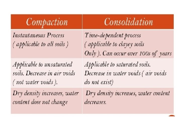
 Compaction and consolidation difference
 Coalescing holes in operating system
 A technique for overcoming internal fragmentation
 Slugging in industrial pharmacy
 Us wick drain
 Nuclear compaction test
 Levels of compaction in dna
 Oragnisation
 Compaction formula
 Define compaction of soil
 Compaction in operating system
 Soil horizon ppt
 Light compaction equipment
 Soil compaction
 Light compaction equipment
 Pressing
 Quality and innovation in product and process design
 Define seminar in nursing management
 Compliance vs quality
 Management gurus and their contributions
 Quality is free
 What is tqm
 Quality control in blood banking
 Quality control of fresh fruits and vegetables
 Shift and trend in quality control
 Qc meaning
 Internal and external qc
 Quality control tools and techniques in project management
 Gauginf
 Difference between inspection and quality control
 Qa ipc
 Total quality control tqc
 Producer's risk
 Average run length in quality control
 Software quality assurance planning
 Quality control log examples
 Quality control shanghai
 Rick benson iris
 Quality control in business plan
 Determination of quality
 Control of raw materials
 Quality control analysis of beer
 Quality control in hematology
 Qrqc format


