BCS Level 4 Certificate in Network and Digital

BCS Level 4 Certificate in Network and Digital Communications Theory QAN 603/0703/1

Networking Basics

No Connection • Single user • No connection • Very secure

Connection • Two users • Crossover cable • Full duplex • Transmit and receive at the same time • OSI layer 1 – Physical • Transmission of bits 1000101010

Hub • Two or more users • A single network segment • Straight cables • OSI layer 1 – Physical 10 10 01 • Transmission of bits • Hub • Amplifies signal • Broadcasts input on all outputs • Clients reject inputs not for them • Half duplex – transmit or receive 01 0 1 10 10 10 01
 Addressing • Uniquely identifies a network interface controller (NIC) •")
MAC (Media Access Control) Addressing • Uniquely identifies a network interface controller (NIC) • MAC addresses are used as a network address for Ethernet and Wi-Fi • Addresses are assigned by the manufacturer and stored in the NIC’s readonly memory or firmware • It is a 48 -bit address for 281, 474, 976, 710, 656 possible MAC addresses (normally shown as 6 octets) ether 4 a: 00: 02: 00: ca: e 0 (from ifconfig) • ipconfig or ifconfig commands show the MAC address

Packets and frames • A MAC address allows data to be directed to a specific device • The data segment is called a frame Preamble Start of frame delimiter Timing 7 bytes FRAME 1 byte Destination Source Length Data CRC MAC Addressing Amount of data Payload Checksum 6 bytes 2 bytes 46 -1500 bytes 4 bytes 6 bytes

Switch • • Two or more users A single network segment Straight cables 10 10 01 11 0 1 11 OSI layer 2 – Data Link • Transmission of packets • Switch • Amplifies signal • Directs inputs to correct outputs • Full duplex • Best performance • Error checking 01 0 1 10 11

Switch operation • Works on the Layer 2 Header • Uses the source and destination MAC addresses to make its forwarding decisions. • MAC Address Table • maps the switch’s ports to MAC addresses • the source address and the port a frame was received on are entered in the MAC Address Table. • as each connected device sends a frame the table gets fully populated • the table is then used to forward frames to their intended destination

Local Area Network • When the area covered is small, such as an office, this is known as a Local Area Network (LAN) • Devices connected to the switches are called Hosts • The hosts are typically clients, servers or LAN attached peripherals, such as printers • A LAN can be wired or wireless • Switches can be cascaded to increase the number of hosts

Increasing the number of hosts • Adding switches is inefficient (inactive hosts are flushed from the MAC address table after 300 s) • Adding hosts increases traffic congestion on the LAN (more collisions and failed transmissions) • Adding hosts means increased processing loads • The solution is to create additional physical networks

IP addresses • A MAC address is physical, it allows packets to be delivered from one NIC to another (hop to hop) • IP addresses are logical and allow delivery of packets across networks (from end to end) • IP addresses work at OSI layer 3 – Network • An address is a 32 bit binary number represented as 4 octets • E. g. 192. 168. 1. 123 (IP v 4) • Destination and source IP addresses are added to the data payload of the ethernet packet

Packets with IP addresses Preamble Start of frame delimiter Timing 7 bytes 1 byte Destination Source Length Data CRC MAC Addressing Amount of data Payload Checksum 6 bytes 2 bytes 46 -1500 bytes 4 bytes 6 bytes PACKET Source IP address Destination IP address 4 bytes

Two networks 192. 168. 1. 9 X R 1 NIC A R 2 NIC B Router 192. 168. 2. 7 192. 168. 1. 12 Source MAC Destination MAC Source IP Destination IP Host A Router R 1 192. 168. 1. 12 192. 168. 2. 7 Router R 2 Host B 192. 168. 1. 12 192. 168. 2. 7

ARP Address Resolution Protocol • Used to find the MAC address for a given IP • Host A (192. 168. 1. 12) needs to send to Host B (192. 168. 2. 7) • It knows 192. 168. 2. 7 is in a different network • It has a default gateway of 192. 168. 1. 1 (the router) • It sends a broadcast ARP message (MAC ff: ff: ff: ff) for 192. 168. 1. 1 (this goes to all hosts on the network) • Only the router replies with its Mac and IP addresses • Host A updates its ARP table • Sends packet to 192. 168. 2. 7 with router MAC address

ARP table
 • Contains a 0. 0")
Router Table In Host A (192. 168. 1. 12) • Contains a 0. 0 entry which points to the default gateway 192. 168. 1. 1 • Contains other IP addresses on its. Interface own network and the address of its Network Destination Gateway Notes own NIC 0. 0 192. 168. 1. 12 127. 0. 0. 1 On-Link 127. 0. 0. 1 Loopback 192. 168. 1. 9 On-Link 192. 168. 1. 12 Host X • If sending to Host X it will look in the table and send directly • If sending to Host B (192. 168. 2. 7) will find 0. 0 as the closest match in the table and send to the gateway

Router’s Table • Contains a list of IP addresses and interfaces IP address Interface 192. 168. 1. 0/24 R 1 NIC 192. 168. 2. 0/24 R 2 NIC • If sending to 192. 168. 1. n will forward via R 1 NIC • If sending to 192. 168. 2. n will forward via R 2 NIC /24 refers indirectly to the number of hosts on the network and is covered in subnetting (not in the BCS Cloud syllabus)

Windows Network Utilities • Ping • Tests connectivity • ping 192. 168. 2. 7 • ARP • Shows MAC addresses for IP addresses

IP addresses • IP address classes Address class First octet range Number of hosts A 1 -126 16 M B 128 -191 64 k C 192 -223 254 • Class D is used for multicast (224 -239) • Class E is experimental (240 -255) • One class A address is worth 16 M hosts • Therefore a way is needed to allocate significantly more hosts than are available

Private IP addresses • Address ranges allocated as private, therefore not permissible onto the general internet. Address range Number of hosts 10. 0 – 10. 255 16 M 172. 16. 0. 0 – 172. 31. 255 1 M 192. 168. 0. 0 – 192. 168. 255 64 K • So, an organisation can have one outward facing IP address and up to 16 M hosts inside • This is done using network address translation (explained later)

Setting IP addresses • Assume a small system with 192. 168. 1. n addresses IP address Host Type 192. 168. 1. 1 Router Static 192. 168. 1. 10 Server Static 192. 168. 1. 20 Printer Static 192. 168. 1. 100 - 200 Desktops Dynamic • Static addresses are set on the device • Dynamic addresses are leased by a DHCP server
 for")
DHCP Dynamic Host Configuration Protocol • Host sends a discovery request (255. 255) for a DHCP server • Server responds with a lease offer of an IP address, gateway address, duration and DNS server address (see later for DNS) • Host responds with a request to accept the offered lease • Server acknowledges the request • Host configures its network interface with the agreed parameters

DHCP Windows Configuration Static Dynamic

Recap • Hosts have MAC and IP addresses • They can communicate in the same network using switches and MAC addressing • To communicate between networks they use routers and IP addresses • Private IP addresses allow duplicate usage in different organisations, but are not allowed on the internet • IP addresses can be manually configured or obtained by DHCP

Internet connection • Connection to the ISP • ADSL • Cable • Satellite • Cellular • Leased line • ISP supplies: • IP address via DHCP • DNS address

ISP IP addresses • An ISP will allocate an IP address from a range it owns • These IP addresses are unique on the internet • Gloucester College IP address is 212. 219. 57. 69 • All internet traffic to and from Gloucester College is via the IP address 212. 219. 57. 69 • Internal IP addresses at the college will be from the private IP addresses ranges • How does traffic for a private IP address get to the right host?
 • Implemented in the router •")
Network and port address translation (NAT and PAT) • Implemented in the router • Allows many hosts on the internal network to connect via one public IP address • Allows many applications on one host to communicate with many services in the cloud • Uses IP and port numbers

Ports • An IP address and a port address make up a socket • Eg 212. 219. 57. 69: 80 (Gloucester college HTTP port) • An application, service or process uses the socket to send and receive data via the network – OSI Layer 4 Transport • The operating system • transmits the data from all application ports on to the network • directs received packets to the matching IP address and port number

Port allocation • Well known ports 0 -1023 • Examples • • • 21 FTP 25 SMTP 80 HTTP 110 POP 3 443 HTTPS • Registered ports 1024 -49151 • Dynamic ports 49152 -65535

Packets with IP addresses and port numbers Preamble Start of frame delimiter Timing 7 bytes 1 byte Destination Source Length Data CRC MAC Addressing Amount of data Payload Checksum 6 bytes 2 bytes 46 -1500 bytes 4 bytes 6 bytes PACKET Source IP address Destination IP address Source port number Destination port number 4 bytes 2 bytes

Browser request Host Router client side Router ISP side Cloud service S 192. 168. 1. 12: 3333 D 216. 58. 218. 206: 80 192. 168. 1. 12: 3333 212. 219. 57. 69: 7777 S 212. 219. 57. 69: 7777 D 216. 58. 218. 206: 80 Host inserts random source port number Router translates internal network IP address to the external network address and port Router updates translate table and records port numbers

Server response Cloud service Router ISP side Router client side Host S 216. 58. 218. 206: 80 D 212. 219. 57. 69: 7777 192. 168. 1. 12: 3333 S 216. 58. 218. 206: 80 D 192. 168. 1. 12: 3333 Server puts source address from received packet into destination address of outbound packet Router translates external network IP address to the internal network address and port Host receives packet and OS directs to correct application

Domain Name System • Translates domain names to IP addresses • A host will query a domain name server (address from DHCP) with the domain name (eg www. techrepublic. com) • DNS server returns the IP address • Windows command: nslookup

Recap • Internal networks connect to the internet via ISP • The ISP allocates an IP address • Network address translation (NAT) allows private IP addressing • Port address translation (PAT) allows multiple applications to connect to cloud services • DNS allows memorable names to be used for cloud resources
 In this key topic, the apprentice")
1. Network Data and Protocols (20%, K 2) In this key topic, the apprentice will describe and explain the common networks in use and their associated data formats, protocols and related performance issues. Outcomes should include an ability to: 1. 1 Describe data formats and protocols in current use 1. 2 Explain features of network protocols in widespread use on the Internet 1. 3 Identify network failure modes and reasons why networks ‘hang’ 1. 4 Describe approaches to error control in a network

1. 1 Describe data formats and protocols in current use A candidate should be able to: • Explain what is meant by data and protocol. • Explain the relationship between data and protocol. • Explain the technical specification of data formats and protocols. • Describe the main features of data formats and protocols such as syntax, synchronisation, error recovery methods and error detection. • Identify what data formats and protocols are in current use such as PPP, 802. 3 and SLIP. • Recognise protocol diagrams such as UML and Time-Sequence.

Data • Data is information that has been translated into a form that is efficient for movement or processing • Relative to today's computers and transmission media, data is information converted into binary digital form • It is acceptable for data to be used as a singular subject or a plural subject • Raw data is a term used to describe data in its most basic digital format • At its most rudimentary level, data is usually in the form of ones and zeros, known as binary data • As all computer data is in binary format, it can be created, processed, saved, and stored digitally • Allows data to be transferred from one computer to another using a network connection or various media devices

Protocol • Network protocols are formal standards and policies comprised of rules, procedures and formats that define communication between two or more devices over a network • Network protocols govern the end-to-end processes of timely, secure and managed data or network communication • These rules include what type of data may be transmitted, what commands are used to send and receive data, and how data transfers are confirmed

Protocols • Protocols exist for several different applications • Examples include wired networking (e. g. , Ethernet), wireless networking (e. g. , 802. 11 ac), and Internet communication (e. g. , IP) • The Internet protocol suite, which is used for transmitting data over the Internet, contains dozens of protocols • May be broken up into four categories: • • Link layer - PPP, DSL, Wi-Fi, etc. Internet layer - IPv 4, IPv 6, etc. Transport layer - TCP, UDP, etc. Application layer - HTTP, IMAP, FTP, etc
 Transport Internet Network Interface (Hardware)")
ISO Model TCP/IP Model Layers Application (Host-to-host) Transport Internet Network Interface (Hardware)

Link Layer Protocols • Establish communication between devices at a hardware level • In order to transmit data from one device to another, each device's hardware must support the same link layer protocol

Internet Layer Protocols • Used to initiate data transfers and route them over the Internet

Transport Layer Protocols • Define how packets are sent, received, and confirmed

Application Layer Protocols • Contain commands for specific applications • For example, a web browser uses HTTPS to securely download the contents of a webpage from a web server • An email client uses SMTP to send email messages through a mail server.

Data Formats • A data format or file format is the format in which the data is coded • The information is coded in such a way that a program or application can recognize, read and use the data • Data transmission occurs: • • In the form of bits (1’s and 0’s) Light Radio Microwave • Can be analogue or digital • Data can be compressed and decompressed

Data Formats - Microwave • Uses a beam of radio waves in the microwave frequency range (6 GHz to 8. 2 GHz) to transmit information between two fixed locations on the earth • Beams are unidirectional • Have high loss due to high frequency • Max distance ~40 km • Use line of sight

Data Formats - Light • Can be laser (Light Amplification by Stimulated Emission of Radiation) (ultraviolet) or normal white light • Ultraviolet waves have wavelengths of 400 to 700 nm • Can be transmitted along optic fibre

Loss of data • Data can become unusable in three different ways: • Loss of bits The carrier is damaged, is lost of its quality deteriorates in such a way that it effect the bits, popularly called 'bit rot‘ • Loss of documentation It is unclear how one file is tied to another, for instance when different versions of a file or the metadata are no longer available, leaving the meaning of the data unclear • Loss of display possibilities The operating system, the hardware or the application are no longer present or cannot be used anymore. That can also be caused by external factors such as computer virus, fire or accidental deleting of files.

1. 2 Explain features of network protocols in widespread use on the Internet. Including, but not limited to: HTTPS HTTP SMTP SNMP TCP UDP IP

HTTP • HTTP is a simple but powerful protocol: • HTTP is connectionless • HTTP is media independent • HTTP is stateless • HTTP is not secure as it is not encrypted • HTTP operates at the highest layer of the TCP/IP model, the Application layer
 • It")
HTTPS • HTTPS is an extension of the Hypertext Transfer Protocol (HTTP) • It is used for secure communication over a computer network, and is widely used on the Internet • HTTPS is not a separate protocol, but refers to use of ordinary HTTP over an encrypted SSL/TLS connection • Operates at the Application layer, as does the TLS security protocol (operating as a lower sublayer of the same layer) • The TLS protocol performs the encryption • HTTPS connections uses a public key certificate for the web server • This certificate must be signed by a trusted certificate authority for the web browser to accept it without warning
 is to")
SMTP • The primary job of the Simple Mail Transfer Protocol (SMTP) is to implement the TCP/IP electronic mail delivery system • SMTP includes a number of other features and capabilities • These allow SMTP to support special requirements and auxiliary needs of the mail system, and are described in detail in RFC 2821 • • • Mail relaying Mail forwarding Mail Gatewaying Address debugging Mailing list expansion Turning

SMTP The SMTP class supports the following Proxy servers: Proxy Name SOCKS 4 proxy. SOCKS 4 A proxy (capable of resolving domain names). SOCKS 5 proxy. HTTP CONNECT HTTP proxy using CONNECT method.

SNMP • Simple Network Management Protocol” is a communications protocol through which an admin, via manager systems and authorized agents, can monitor and even manipulate some aspects of a networks configuration and traffic • SNMP is an open internet standard for managing networked devices (systems) • three versions of SNMP that define approved standards: • SNMPv 1 • SNMPv 2 (also known, and referred to in this document, as SNMPv 2 c) • SNMPv 3

SMNP • Main features: • Managers and Agents • SNMP is a network protocol that allows devices to be managed remotely by a network management station (NMS), also commonly called a manager. • To be managed, a device must have an SNMP agent associated with it. The purpose of the agent is to: • Receive requests for data representing the state of the device from the manager, and provide an appropriate response • Accept data from the manager to enable control of the device state • Generate SNMP traps, which are unsolicited messages sent to one or more selected mangers to signal significant events relating to the device
: • Management Information Base • To manage and monitor")
SMNP • Main Features (cont): • Management Information Base • To manage and monitor a device, its characteristics must be represented using a format known to both the agent and the manager • These characteristics can represent physical properties such as fan speeds, or services such as routing tables • The data structure defining these characteristics is known as a management information base (MIB) • In response to a get operation, the agent provides data, either maintained locally or directly from the managed device • In response to a set operation, the agent typically performs some action affecting the state of either itself or the managed device
: • MIB Tables • Much of the data content")
SMNP • Main Features (cont): • MIB Tables • Much of the data content defined by MIBs is in tabular form, and organized as entries consisting of a sequence of objects, each with its own OIDs. For example, a table of fan characteristics could consist of a number of rows, one per fan, with each row containing columns corresponding to the current speed, the expected speed, and the minimum acceptable speed • The addressing of the rows within the table can be as follows: • Simple, single-dimensional index (a row number within the table, for example `6') • More complex, multidimensional, instance specifier such as an IP address and port number (for instance, 127. 0. 0. 1, 1234)
: • Access Control • All addressable objects defined in")
SMNP • Main Features (cont): • Access Control • All addressable objects defined in the MIB have associated maximum access rights, for instance, read-only or read-write • These determine the maximum access the agent can support, and can be used by the manager to restrict the operations it will permit the operator to attempt • The agent is able to apply lower access rights as required, that is, it is able to refuse writes to objects that are considered read-write • This refusal can be on the basis of: • How applicable the operation is to the object being addressed (for example, where an object defined by the MIB represents a state machine for which only certain transactions are legal) • Security restrictions that limit certain operations to restricted sets of managers
 is considered as a reliable")
TCP • Transmission Control Protocol (TCP - RFC 793) is considered as a reliable protocol • Transmission Control Protocol (TCP) is responsible for breaking up the message (Data from application layer) into TCP Segments and reassembling them at the receiving side • It is not sure that the data reaching at the receiving device is in the same order as the sending side, because of the problems in network or different paths packets flow to the destination • TCP is responsible for keeping the unordered segments in the right order • TCP assures a reliable delivery by resending anything that gets lost while traveling the network

TCP - Characteristics • Stream Data transfer: • Applications working at the Application Layer transfers a contiguous stream of bytes to the bottom layers • It is the duty of TCP to pack this byte stream to packets, known as TCP segments, which are passed to the IP layer for transmission to the destination device • The application does not have to bother to chop the byte stream data packets

TCP - Characteristics • Reliability: • The most important feature of TCP is reliable data delivery. In order to provide reliability, TCP must recover from data that is damaged, lost, duplicated, or delivered out of order by the Network Layer • TCP assigns a sequence number to each byte transmitted, and expects a positive acknowledgment (ACK) from the receiving TCP layer • If the ACK is not received within a timeout interval, the data is retransmitted • The receiving TCP uses the sequence numbers to rearrange the TCP segments when they arrive out of order, and to eliminate duplicate TCP segments

TCP - Characteristics • Flow control: • Network devices operate at different data rates because of various factors like CPU and available bandwidth • It may happen a sending device to send data at a much faster rate than the receiver can handle • TCP uses a sliding window mechanism for implementing flow control • The number assigned to a segment is called the sequence number and this numbering is actually done at the byte level • The TCP at the receiving device, when sending an ACK back to the sender, also indicates to the TCP at the sending device, the number of bytes it can receive (beyond the last received TCP segment) without causing serious problems in its internal buffers

TCP - Characteristics • Multiplexing: • Multitasking achieved through the use of port numbers • Connections: • Before application processes can send data by using TCP, the devices must establish a connection • The connections are made between the port numbers of the sender and the receiver devices • A TCP connection identifies the end points involved in the connection • A socket number is a combination of IP address and port number, which can uniquely identify a connection • Full duplex: • TCP provides for concurrent data streams in both directions

IP • Internet Protocol • Principal communications protocol in the Internet protocol suite for relaying datagrams across network boundaries • Its routing function enables internetworking, and essentially establishes the Internet • Addressing • IP packet headers contain addresses that identify the sending computer and the receiving computer • Routers use this information to guide each packet across communication networks and connect the sending and receiving computers

IP • Reassembly • Internet Protocol keeps track of the way messages between computers are broken into packets • Since most messages are too big to fit in one packet, and since packets aren't sent in any organized order, they must be reassembled as they arrive at the recipient • IP dictates how packets are reassembled into usable messages

IP – Frame Format
 that enable communication between")
TCP/IP • TCP/IP is a set of protocols (Protocol Suit) that enable communication between computers • It is a tested and proved protocol suit • Features: • • Multi-vendor support Iteroperability Logical addressing Routability Name resolution Error control and flow control Multiplexing/de-multiplexing

TCP – Frame Format

UDP • User Datagram Protocol • • Provides connectionless, unreliable service So UDP faster than TCP Adds only checksum and process-to-process addressing to IP Used for DNS and NFS Used when socket is opened in datagram mode It sends bulk quantity of packets No acknowledgment Good for video streaming: it is an unreliable protocol

UDP – Frame Format

1. 3 Identify network failure modes and reasons why networks ‘hang’ A candidate should be able to: • Describe failure modes in protocols. • Describe the effect on a protocol of data communication errors. • Describe causes for network failures. • Explain the causes for system 'hangs'.

The Effect On A Protocol Of Data Communication Errors • Error control is the technique of detecting and correcting blocks of data during communication • It checks the reliability of characters both at the bit level and packet level • If proper error control is in place, transmitted and received data is ensured to be identical, as in many cases communication channels can be highly unreliable • Data can be corrupted while in transmission • In order to retain reliable communication, errors must be detected and corrected • Forward error control and feedback error control are the two types of errorcontrol mechanisms used in communications

Causes for Network Failures • Misconfiguration • Security breaches • Old equipment • Human error • Incompatible changes • Hardware failures • Power failures

Causes for System 'Hangs' • CPU • RAM • NIC failure • Overheating • Software errors • Electrical problems • Environment

1. 4 Describe approaches to error control in a network A candidate should be able to: • Describe at least one approach to error control in a network such as; forward error control, feedback error control and block error control. • Identify methods of error control, such as checksum, parity and redundancy.

Forward Error Control • In forward error control, additional redundant information is also transmitted along with the data • This helps the receiver to detect and determine the location of the error in the transmitted data • Forward error control is less commonly used due to the amount of additional redundant information which is transmitted.

Feedback Error Control • In backward or feedback error control, along with each character, a little additional information is provided for the detection of errors • The receiver in this technique performs no error correction • If the received data is found to contain errors, the entire data is retransmitted

Methods of Error Control • Checksum • Parity • Redundancy

Checksum • A checksum is an error-detection method in a the transmitter computes a numerical value according to the number of set or unset bits in a message and sends it along with each message frame • At the receiver end, the same checksum function (formula) is applied to the message frame to retrieve the numerical value • A checksum error means there was a problem with the serial communications • A checksum is created based on the data values in the data blocks to be transmitted using some algorithm and appended to the data • When the receiver gets this data, a new checksum is calculated and compared with the existing checksum

Parity • Historically the most commonly used data integrity method • Parity can detect - but not correct - single-bit errors • Error Correction Code (ECC) is a more comprehensive method of data integrity checking that can detect and correct single-bit errors
: • CRC is based on binary division. •")
Redundancy • Cyclic Redundancy Check (CRC): • CRC is based on binary division. • A sequence of redundant bits called CRC or the CRC remainder is appended to the end of a data unit, so that the resulting data unit becomes exactly divisible by a second, predetermined binary number • At its destination, the incoming data unit is divided by the same number • If at this step there is no remainder, the data unit is assumed to be intact and therefore is accepted

End of Day 1
 In this key topic, the apprentice will")
2. Layered Network Models (20%, K 2) In this key topic, the apprentice will be able to explain network layer models and then contrast their differences. Outcomes should include an ability to: 2. 1 Explain features layered network models 2. 2 Compare the differences between the following physical layer categories and datalink layer protocols

2. 1 Explain features of the following layered network models: TCP/IP Reference Model OSI 7 Layer Model

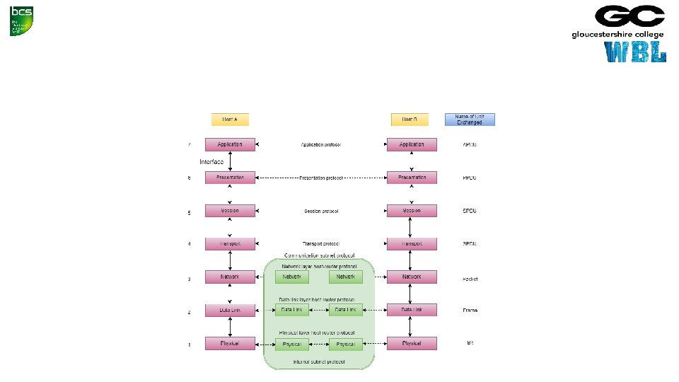
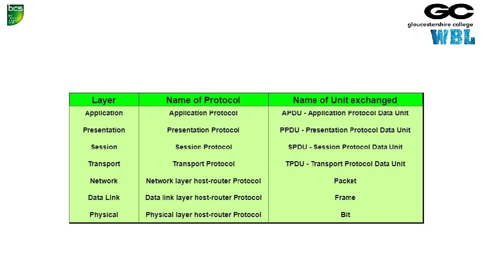
OSI • Systems must be developed which are compatible to communicate with each other ISO has developed a standard • ISO stands for International organization of Standardization • This is called a model for Open System Interconnection (OSI) and is commonly known as OSI model • The ISO-OSI model is a seven layer architecture. It defines seven layers or levels in a complete communication system • They are: • • • Application Layer Presentation Layer Session Layer Transport Layer Network Layer

Feature of OSI Model • Big picture of communication over network is understandable through this OSI model • We see how hardware and software work together • We can understand new technologies as they are developed • Troubleshooting is easier by separate networks • Can be used to compare basic functional relationships on different networks

Functions of Different Layers • Following are the functions performed by each layer of the OSI model • This is just an introduction, we will cover each layer in details in the coming tutorials

OSI Model Layer 1: The Physical Layer • Physical Layer is the lowest layer of the OSI Model. • It activates, maintains and deactivates the physical connection. • It is responsible for transmission and reception of the unstructured raw data over network. • Voltages and data rates needed for transmission is defined in the physical layer. • It converts the digital/analog bits into electrical signal or optical signals. • Data encoding is also done in this layer.

OSI Model Layer 2: Data Link Layer • Data link layer synchronizes the information which is to be transmitted over the physical layer • The main function of this layer is to make sure data transfer is error free from one node to another, over the physical layer • Transmitting and receiving data frames sequentially is managed by this layer. • This layer sends and expects acknowledgements for frames received and sent respectively • Resending of non-acknowledgement received frames is also handled by this layer • This layer establishes a logical layer between two nodes and also manages the Frame traffic control over the network

OSI Model Layer 3: The Network Layer • Network Layer routes the signal through different channels from one node to other • It acts as a network controller • It manages the Subnet traffic • It decides by which route data should take • It divides the outgoing messages into packets and assembles the incoming packets into messages for higher levels

OSI Model Layer 4: Transport Layer • Transport Layer decides if data transmission should be on parallel path or single path • Functions such as Multiplexing, Segmenting or Splitting on the data are done by this layer • It receives messages from the Session layer above it, convert the message into smaller units and passes it on to the Network layer • Transport layer can be very complex, depending upon the network requirements • Transport layer breaks the message (data) into small units so that they are handled more efficiently by the network layer

OSI Model Layer 5: The Session Layer • Session Layer manages and synchronize the conversation between two different applications. • Transfer of data from source to destination session layer streams of data are marked and are resynchronized properly, so that the ends of the messages are not cut prematurely and data loss is avoided

OSI Model Layer 6: The Presentation Layer • Presentation Layer takes care that the data is sent in such a way that the receiver will understand the information (data) and will be able to use the data • While receiving the data, presentation layer transforms the data to be ready for the application layer • Languages(syntax) can be different of the two communicating systems • Under this condition presentation layer plays a role of translator • It performs Data compression, Data encryption, Data conversion etc.

OSI Model Layer 7: Application Layer • Application Layer is the topmost layer • Transferring of files disturbing the results to the user is also done in this layer • Mail services, directory services, network resource etc. are services provided by application layer • This layer mainly holds application programs to act upon the received and to be sent data

Merits of OSI reference model • OSI model distinguishes well between the services, interfaces and protocols • Protocols of OSI model are very well hidden • Protocols can be replaced by new protocols as technology changes • Supports connection oriented services as well as connectionless service

Demerits of OSI reference model • Model was devised before the invention of protocols • Fitting of protocols is tedious task • It is just used as a reference model

TCP/IP • The TCP/IP model was developed prior to the OSI model • The TCP/IP model is not exactly similar to the OSI model • The TCP/IP model consists of five layers: • • • the application layer transport layer network layer data link layer physical layer • The first four layers provide physical standards, network interface, internetworking, and transport functions that correspond to the first four layers of the OSI model and these four layers are represented in TCP/IP model by a single layer called the application layer

Functions of TCP/IP layers

Network Access Layer • A network layer is the lowest layer of the TCP/IP model • A network layer is the combination of the Physical layer and Data Link layer defined in the OSI reference model • It defines how the data should be sent physically through the network. • This layer is mainly responsible for the transmission of the data between two devices on the same network • The functions carried out by this layer are encapsulating the IP datagram into frames transmitted by the network and mapping of IP addresses into physical addresses • The protocols used by this layer are ethernet, token ring, FDDI, X. 25, frame relay

Internet Layer • An internet layer is the second layer of the TCP/IP model • An internet layer is also known as the network layer • The main responsibility of the internet layer is to send the packets from any network, and they arrive at the destination irrespective of the route they take

Following are the protocols used in this layer • IP Protocol • ARP Protocol • ICMP Protocol

Responsibilities of the IP protocol • IP Addressing: • This protocol implements logical host addresses known as IP addresses. The IP addresses are used by the internet and higher layers to identify the device and to provide internetwork routing. • Host-to-host communication: • It determines the path through which the data is to be transmitted. • Data Encapsulation and Formatting: • An IP protocol accepts the data from the transport layer protocol. An IP protocol ensures that the data is sent and received securely, it encapsulates the data into message known as IP datagram. • Fragmentation and Reassembly: • The limit imposed on the size of the IP datagram by data link layer protocol is known as Maximum Transmission unit (MTU). If the size of IP datagram is greater than the MTU unit, then the IP protocol splits the datagram into smaller units so that they can travel over the local network. Fragmentation can be done by the sender or intermediate router. At the receiver side, all the fragments are reassembled to form an original message. • Routing: • When IP datagram is sent over the same local network such as LAN, MAN, WAN, it is known as direct delivery. When source and destination are on the distant network, then the IP datagram is sent indirectly. This can be accomplished by routing the IP datagram through various devices such as routers.

ARP Protocol • ARP stands for Address Resolution Protocol • ARP is a network layer protocol which is used to find the physical address from the IP address • The two terms are mainly associated with the ARP Protocol: • ARP request: When a sender wants to know the physical address of the device, it broadcasts the ARP request to the network • ARP reply: Every device attached to the network will accept the ARP request and process the request, but only recipient recognize the IP address and sends back its physical address in the form of ARP reply • The recipient adds the physical address both to its cache memory and to the datagram header

ICMP Protocol • ICMP stands for Internet Control Message Protocol • It is a mechanism used by the hosts or routers to send notifications regarding datagram problems back to the sender • A datagram travels from router-to-router until it reaches its destination. If a router is unable to route the data because of some unusual conditions such as disabled links, a device is on fire or network congestion, then the ICMP protocol is used to inform the sender that the datagram is undeliverable • An ICMP protocol mainly uses two terms: • ICMP Test: ICMP Test is used to test whether the destination is reachable or not • ICMP Reply: ICMP Reply is used to check whether the destination device is responding or not • The core responsibility of the ICMP protocol is to report the problems, not correct them • The responsibility of the correction lies with the sender • ICMP can send the messages only to the source, but not to the intermediate routers because the IP datagram carries the addresses of the source and destination but not of the router that it is passed to

Transport Layer • The transport layer is responsible for the reliability, flow control, and correction of data which is being sent over the network

Transport Layer • The two protocols used in the transport layer are User Datagram protocol and Transmission control protocol
 • It provides connectionless service and end-to-end delivery of transmission")
User Datagram Protocol (UDP) • It provides connectionless service and end-to-end delivery of transmission • It is an unreliable protocol as it discovers the errors but not specify the error • User Datagram Protocol discovers the error, and ICMP protocol reports the error to the sender that user datagram has been damaged • UDP consists of the following fields: Source port address: The source port address is the address of the application program that has created the message Destination port address: The destination port address is the address of the application program that receives the message Total length: It defines the total number of bytes of the user datagram in bytes. Checksum: The checksum is a 16 -bit field used in error detection • UDP does not specify which packet is lost. UDP contains only checksum; it does not contain any ID of a data segment
")
User Datagram Protocol (UDP)
 • It provides a full transport layer services to applications")
Transmission Control Protocol (TCP) • It provides a full transport layer services to applications • It creates a virtual circuit between the sender and receiver, and it is active for the duration of the transmission • TCP is a reliable protocol as it detects the error and retransmits the damaged frames • Therefore, it ensures all the segments must be received and acknowledged before the transmission is considered to be completed and a virtual circuit is discarded • At the sending end, TCP divides the whole message into smaller units known as segment, and each segment contains a sequence number which is required for reordering the frames to form an original message

Application Layer • An application layer is the topmost layer in the TCP/IP model • It is responsible for handling high-level protocols, issues of representation • This layer allows the user to interact with the application • When one application layer protocol wants to communicate with another application layer, it forwards its data to the transport layer • There is an ambiguity that occurs in the application layer • Every application cannot be placed inside the application layer except those who interact with the communication system • For example: text editor cannot be considered in application layer while web browser using HTTP protocol to interact with the network where HTTP protocol is an application

Main Protocols Used in the Application Layer • HTTP: HTTP stands for Hypertext transfer protocol. This protocol allows us to access the data over the world wide web. It transfers the data in the form of plain text, audio, video. It is known as a Hypertext transfer protocol as it has the efficiency to use in a hypertext environment where there are rapid jumps from one document to another. • SNMP: SNMP stands for Simple Network Management Protocol. It is a framework used for managing the devices on the internet by using the TCP/IP protocol suite. • SMTP: SMTP stands for Simple mail transfer protocol. The TCP/IP protocol that supports the e-mail is known as a Simple mail transfer protocol. This protocol is used to send the data to another e-mail address. • DNS: DNS stands for Domain Name System. An IP address is used to identify the connection of a host to the internet uniquely. But, people prefer to use the names instead of addresses. Therefore, the system that maps the name to the address is known as Domain Name System. • TELNET: It is an abbreviation for Terminal Network. It establishes the connection between the local computer and remote computer in such a way that the local terminal appears to be a terminal at the remote system. • FTP: FTP stands for File Transfer Protocol. FTP is a standard internet protocol used for transmitting the files from one computer to another computer.

2. 2 Compare the differences between the following physical layer categories and datalink layer protocols: Physical Layers (including, but not limited to: Wireless, Fibre, Wired) Data Link Layer (including, but not limited to: Ethernet [802. 3], Wireless LAN [802. 11], Bluetooth)

• Done

Digital Transmission • DIGITAL-TO-DIGITAL CONVERSION • Digital-to-digital encoding is the representation of digital information by a digital signal • When binary 1 s and 0 s generated by the computer are translated into a sequence of voltage pulses that can be propagated over a wire, this process is known as digital-to-digital encoding

ANALOG-TO-DIGITAL CONVERSION • When an analog signal is digitalized, this is called an analog-to-digital conversion • Suppose human sends a voice in the form of an analog signal, we need to digitalize the analog signal which is less prone to noise • It requires a reduction in the number of values in an analog message so that they can be represented in the digital stream • In analog-to-digital conversion, the information contained in a continuous wave form is converted in digital pulses

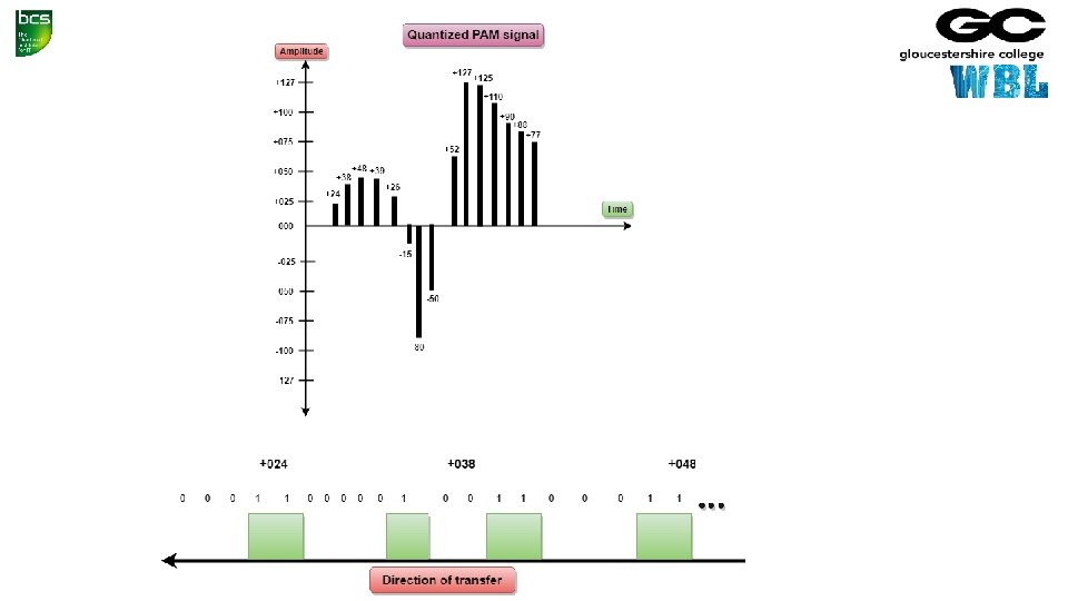
Techniques for Analog-To-Digital Conversion • PAM stands for pulse amplitude modulation • PAM is a technique used in analog-to-digital conversion • PAM technique takes an analog signal, samples it, and generates a series of digital pulses based on the result of sampling where sampling means measuring the amplitude of a signal at equal intervals • PAM technique is not useful in data communication as it translates the original wave form into pulses, but these pulses are not digital • To make them digital, PAM technique is modified to PCM technique
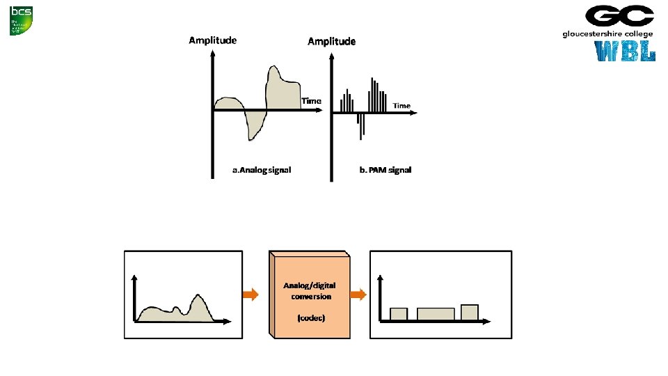

PCM • PCM stands for Pulse Code Modulation • PCM technique is used to modify the pulses created by PAM to form a digital signal. To achieve this, PCM quantizes PAM pulses • Quantization is a process of assigning integral values in a specific range to sampled instances • PCM is made of four separate processes: PAM, quantization, binary encoding, and digital-to-digital encoding.

End of Day 2
 In this key topic, the apprentice will")
3. Network Routing Protocols (30%, K 3) In this key topic, the apprentice will describe and explain network routing protocols. Outcomes should include an ability to: 3. 1 Describe current network routing protocols in use 3. 2 Compare the differences between static and dynamic routing

3. 1 Describe current network routing protocols in use; including, but not limited to: RIP/RIP 2 RIP-NG OSPFv 2 OSPFv 3 A candidate should be able to: • Explain the technical specification of network routing protocols. • Describe the main features of network routing protocols. • Explain the advantages and disadvantages of current network routing protocols, such as security, complexity / simplicity, resilience and scalability

This table lists the administrative distance default values of the protocols Route Source Default Distance Values Connected interface 0 Static route 1 Enhanced Interior Gateway Routing Protocol (EIGRP) summary route 5 External Border Gateway Protocol (BGP) 20 Internal EIGRP 90 IGRP 100 OSPF 110 Intermediate System-to-Intermediate System (IS-IS) 115 Routing Information Protocol (RIP) 120 Exterior Gateway Protocol (EGP) 140 On Demand Routing (ODR) 160 External EIGRP 170 Internal BGP 200 Unknown* 255
 is a dynamic")
Routing Information Protocol - RIP/RIP 2 • Routing Information Protocol (RIP) is a dynamic routing protocol which uses hop count as a routing metric to find the best path between the source and the destination network • It is a distance vector routing protocol which has an administrative distance (AD) value 120 and works on the application layer of OSI model • RIP uses port number 520 • It is an Interior Gateway Protocol (IGP)

Hop Count • Hop count is the number of routers occurring in between the source and destination network • The path with the lowest hop count is considered as the best route to reach a network and therefore placed in the routing table • RIP prevents routing loops by limiting the number of hopes allowed in a path from source and destination • The maximum hop count allowed for RIP is 15 and hop count of 16 is considered as network unreachable

Features of RIP • Updates of the network are exchanged periodically • Updates (routing information) are always broadcast • Full routing tables are sent in updates • Routers always trust on routing information received from neighbor routers • This is also known as ‘Routing on rumours’ • RIP requires routers to send the entire routing table to neighbours every 30 seconds

RIP versions RIP v 1 RIP v 2 RIPng Sends update as broadcast Sends update as multicast Broadcast at 255 Multicast at 224. 0. 0. 9 Multicast at FF 02: : 9 (RIPng can only run on IPv 6 networks) Doesn’t support authentication of update messages Supports authentication of RIPv 2 update messages Classful routing protocol Classless protocol, supports classful – Classless updates are sent RIP v 1 is known as Classful Routing Protocol because it doesn’t send information of subnet mask in its routing update RIP v 2 is known as Classless Routing Protocol because it sends information of subnet mask in its routing update

RIP-NG • RIP-ng is an extension of RIP developed for support of IPv 6 • Features: • just like RIP for IPv 4, it uses hop count as the metric • sends updates every 30 seconds • RIPng messages use the UDP port 521 and the multicast address of FF 02: : 9
, and OSPF (Open Shortest")
OSPF • Routers connect networks using the Internet Protocol (IP), and OSPF (Open Shortest Path First) is a router protocol used to find the best path for packets as they pass through a set of connected networks • OSPF is an Interior Gateway Protocols (IGPs): that is, protocols aimed at traffic moving around within a larger autonomous system network like a single enterprise's network, which may in turn be made up of many separate local area networks linked through routers • The OSPF routing protocol has largely replaced the older Routing Information Protocol (RIP) in corporate networks

OSPF • Routers that use OSPF learns about changes to the network • It reads the routing table, learns of a change, and immediately broadcasts it to all other OSPF hosts in the network • OSPF sends only the part that has changed and only when a change has taken place • When routes change -- sometimes due to equipment failure -- the time it takes OSPF routers to find a new path between endpoints with no loops (which is called "open") and that minimizes the length of the path is called the convergence time

OSPF • Rather than simply counting the number of router hops between hosts on a network, as RIP does, OSPF bases its path choices on "link states" • This takes into account additional network information, including IT-assigned cost metrics that give some paths higher assigned costs • OSPF has RIP support built in both for router-to-host communication and for compatibility with older networks using RIP as their primary protocol

OSPF v 2 • A routing protocol which is described in RFC 2328 • OSPFv 2 is an IGP • See previous slides • (OSPF v 1 (RFC 1131) has never gone beyond the experimental stage)

OSPFv 3 • OSPFv 3 is the Open Shortest Path First routing protocol for IPv 6 • It is similar to OSPFv 2 in its concept of a link state database, intra- and interarea, and AS external routes and virtual links • OSPFv 3 still establishes neighbour adjacencies, has areas, different network types, the same metrics, runs SPF, etc. • There are however some differences • OSPFv 2 runs on top of IPv 4 and since OSPFv 3 runs on IPv 6, some changes had to be made

OSPF Differences

3. 2 Compare the differences between static and dynamic routing A candidate should be able to: • Explain the static and dynamic routing. • Compare static and dynamic routing. • Explain the advantages and disadvantages of static and dynamic routing such as security, complexity / simplicity, resilience and scalability.

Static And Dynamic Routing • Routers are designed to communicate with each other and to share information about networks • Routers can be configured to work with static and dynamic routes

Static Routing • A Static route is a route that is manually entered by a network administrator • This is known as non-adaptive routing because the router will always use this static route when sending data • The data path is predetermined by the administrator • Static routes are useful for network security • A fault with any of the routes requires the system administrator to go to the affected routers and make the required changes to get the system working again • The overuse of static routing is not recommended because the main function of a router is to learn and devise new paths for data in the event of system failures

Dynamic Routing • Most routers are dynamic with the capability of being statically configured • Dynamic routing involves the regular communication of routers with other routers • Allows the routers to learn and adapt to a changing environment • This is the embodiment of packet switching with routers automatically adapting to network changes and even system failures
 In this key topic, the apprentice will describe")
4. Network Performance (30%, K 3) In this key topic, the apprentice will describe and explain the factors that affect network performance. Outcomes should include an ability to: 4. 1 Demonstrate the relationship between factors that affect network performance 4. 2 Explain methods of improving network performance

4. 1 Demonstrate the relationship between factors that affect network performance Bandwidth Number of users Nature Contention A candidate should be able to: • Describe the factors affecting network performance (such as Bandwidth, Number of users, Nature of traffic, traffic contention) and explain how they affect performance. • Explain the interaction between the factors (e. g. how a change in one factor will affect other factors).


4. 2 Explain methods of improving network performance, such as traffic shaping, architecture and network policy A candidate should be able to: • Explain methods of network management such as traffic shaping, network architecture and network policies. • Explain the effects of network management on users. • Explain common causes of sub-optimal network performance such as bottlenecks and streaming.
- Slides: 146