AnNajah National University Facility of Engineering and Information


")

 28 Modulus of Elasticity")
 35 Modulus of Elasticity")
 420 Modulus of Elasticity")


")

 = 1. 65")


")


 Section")


")

 check")


")


")
 – Section 1")
 – Section 2")
 – Section 3")


 load")


 Average (mm) ratio B 2 0. 65 0. 641 1.")
 Average (mm) ratio B 2 0. 765 0. 6915 1.")


")


- Slides: 121
An-Najah National University Facility of Engineering and Information Technology Civil Engineering department Structural Analysis and Design of Clock tower in Jenin By: Mohammad Hijjawi, Nour Abu Hantash, Omar Yasin, Mohammad Bzoor
Content 1 – Introduction: • • • Project description Codes used Material Seismicity of Site and Structure Loads and Load Combinations 2 – Preliminary design: • • Beam preliminary design Slab preliminary design Column preliminary design Walls preliminary design
Content 3 – Modeling and Analysis: • • • Introduction Definition of materials and sections Definition of response spectrum 4 – Modeling and Analysis: • • Checks Compatibility check Equilibrium check Internal force check Irregularities check Drift check P-delta check
Content 5 – Design and Detailing: • • Programs and sheets used Beam design Column design Walls design Slab design Mat foundation design Folded shell design
PART 1: INTRODUCTION
3 D VIEW
3 D VIEW
3 D VIEW
PLAN VIEW (Basement)
CODES AND STANDARDS • ACI 318 -14 • IBC 2015 • ASCE 7 -10
MATERIALS • 28 MPa concrete Property Value Compressive strength (Mpa) 28 Modulus of Elasticity E (Mpa) 24870 Unit Weight (Kn/m) 25 Table 1: Concrete 28 properties
MATERIALS • 35 Mpa concrete Property Value Compressive strength (Mpa) 35 Modulus of Elasticity E (Mpa) 27800 Unit Weight (Kn/m) 25 Table 2: Concrete 35 properties
MATERIALS • Steel Grade 60 Property Value Yielding Strength (Mpa) 420 Modulus of Elasticity E (Gpa) 200 Table 3: Steel grade 60 properties
MATERIALS • Non-structural materials Material Ɣ in k. N/m³ Blocks 12 Filling Materials 18 Tiles 26 Plaster 23 Aggregate 13 Concrete Mortar 23 Masonry Stone 26 Table 4: Non structural materials properties
SEISMICITY OF SITE AND STRUCTURE
SEISMICITY OF SITE AND STRUCTURE • SS = 2. 5 Z • S 1 = 1. 25 Z • Z for Jenin = 0. 2 SS= 0. 5, S 1 = 0. 25 SS(2%) = 0. 75, S 1(2%) = 0. 375
SEISMICITY OF SITE AND STRUCTURE Site class Stiff Soil (D)
SEISMICITY OF SITE AND STRUCTURE Site Coefficient Fa = 1. 2
SEISMICITY OF SITE AND STRUCTURE Site Coefficient Fv (by interpolation) = 1. 65
SEISMICITY OF SITE AND STRUCTURE
SEISMICITY OF SITE AND STRUCTURE Determination of risk category Risk Category = III
SEISMICITY OF SITE AND STRUCTURE Determination of seismic design category Seismic design category =D
Structural system used Structural system Special reinforced concrete shear walls
Loads and Load Combinations Gravity Loads
Loads and Load Combinations Lateral Load • The method used in determination the effect of earthquake load is modal response method. • Verified by ELF
Loads and Load Combinations Ultimate Load Combinations: • • • 1. 4 D 1. 2 D +1. 6 L 1. 32 D +L +1. 3 EQx +0. 39 EQy 1. 32 D +L +1. 3 EQy +0. 39 EQx 0. 78 D +1. 3 EQx +0. 39 EQy 0. 78 D +1. 3 EQy +0. 39 EQx
Loads and Load Combinations Service Load Combinations: • • D+L 1. 084 D+0. 91 EQx+0. 273 EQy 1. 084 D+0. 91 EQy+0. 273 EQx 1. 063 D +0. 75 L +0. 683 EQx +0. 205 EQy 1. 063 D +0. 75 L +0. 683 EQy +0. 205 EQx 0. 516 D+0. 91 EQx+0. 273 EQy 0. 516 D+0. 91 EQy+0. 273 EQx
End of Part 1 Part 2: Preliminary design
Part 2: Preliminary design Beam preliminary design
Part 2: Preliminary design Columns preliminary design v Circular columns with diameter of 1000 mm. v Rectangular columns of 800 X 400, 700 x 400.
Part 2: Preliminary design Walls preliminary design v 350 mm v 250 mm Based on architectural drawings
Part 2: Preliminary design Folded shell preliminary design H = 15 cm Depth = 1. 5 m
Part 2: Preliminary design Slab preliminary design Two way solid slab
Part 2: Preliminary design Slab preliminary design
Part 2: Preliminary design Check shear
Part 2: Final dimension • Walls: Wall 300 mm Wall 400 mm Wall 250 mm
Part 2: Final dimension • Beams: Beam 400 X 500 Beam 500 X 600
Part 2: Final dimension • Columns: Column 700 X 400 Column 800 X 400 Column 900 X 500 Column D = 1000 mm Column D = 800 mm
PLAN VIEW (Basement - Columns)
End of Part 2 Part 3: Modeling
Part 3: Modeling v Modeling and analysis are performed by using ETABS 18 program. v All supports are modeled as Fixed support. v Ultimate strength method (LRFD) is used. v Exterior partition as linear load and interior partition as distributed load.
Steel material
Concrete material
Slab section
Column section
Wall section
Beam (500 x 400) Section
Load patterns
Load combinations
Mass Source definition
Response spectrum definition
ELF – EQX Defintion
Modal EQX Defintion (Load Case)
End of Part 3 Part 4: Checks
Part 4: Checks v Compatibility check v Equilibrium check v Stress-Strain (Internal force) check v Base shear check v Modal mass participation ratio check v Irregularities check v Drift check v P-delta check
Compatibility check
Equilibrium check
Stress – Strain Check Column C 1, 400 X 700 mm at Basement 2
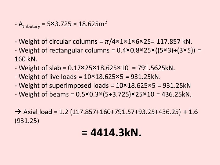
- Atributary = 4. 465 × 5. 5 = 24. 6 m 2 - Weight of column = 0. 4 × 0. 7 × 25 × 30 = 210 k. N. - Weight of slab = 0. 17 × 25 × 24. 6 × 8 = 836. 4 k. N. - Weight of live loads = 8 × 24. 6 × 5 = 984 k. N. - Weight of superimposed loads = 8*24. 6*5 = 984 k. N - Weight of beams = 0. 5 × 0. 4 × (4. 465+5. 5) × 25 × 8 = 298. 95 k. N. Axial load = 1. 2 (210+836. 4+984+298. 95) + 1. 6 (984) = 4369. 62 k. N.
ETABS result, C 1, 400 x 700 (B 2)
Column C 9 at Basement 2
ETABS result, Column C 9 at Basement 2
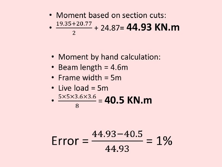
Stress-strain check (Beam)
Stress-strain check (Beam) – Section 1
Stress-strain check (Beam) – Section 2
Stress-strain check (Beam) – Section 3
Base shear check Manually V= Cs. W = 0. 09 × 141218. 3 = 12409. 7 k. N. ETABS
Base shear check
Base shear check Result from ETABS, Modal resposne
Modal Mass Participation Ratio
Modal Mass Particpation Ratio
Drift Check v All supports are assumed to be pinned v Service (Allowable) load combinations are used
Drift Check
Drift Check Floor F 7 F 6 F 5 F 4 F 3 F 2 F 1 GF GF B 1 B 2 Max Max Max Max Max X Y X Y X Y Elastic drift Inelastic Max drift / / Story drift / Story story height 0. 001977 0. 007908 0. 015 0. 001903 0. 007612 0. 015 0. 001371 0. 005484 0. 015 0. 001685 0. 00674 0. 015 0. 001335 0. 00534 0. 015 0. 001902 0. 007608 0. 015 0. 001363 0. 005452 0. 015 0. 001942 0. 007768 0. 015 0. 00135 0. 0054 0. 015 0. 00191 0. 00764 0. 015 0. 001315 0. 00526 0. 015 0. 001838 0. 007352 0. 015 0. 001142 0. 004568 0. 015 0. 001564 0. 006256 0. 015 0. 000832 0. 003328 0. 015 0. 001117 0. 004468 0. 015 0. 00047 0. 00188 0. 015 0. 000551 0. 002204 0. 015 0. 000231 0. 000924 0. 015 0. 000253 0. 001012 0. 015
Story Max drift (mm) Average (mm) ratio B 2 0. 65 0. 641 1. 014041 B 1 2. 03 GF 6. 19 6. 125 1. 010612 F 1 11. 665 11. 712 0. 995987 F 2 18. 196 18. 1185 1. 004277 F 3 22. 345 22. 2155 1. 005829 F 4 22. 441 24. 257 0. 925135 F 5 29. 77 29. 97 0. 993327 F 6 33. 876 2. 02 33. 9035 1. 00495 0. 999189 Torsional Irregularity check (X-direction)
Story Max drift (mm) Average (mm) ratio B 2 0. 765 0. 6915 1. 106291 B 1 2. 469 2. 206 1. 11922 GF 7. 574 6. 762 1. 120083 F 1 14. 51 12. 905 1. 12437 F 2 24. 558 21. 7 1. 131705 F 3 30. 1 26. 4 1. 140152 F 4 35. 6 31 1. 148387 F 5 41. 4 35. 9 1. 153203 F 6 42. 5 35. 7 1. 167147 Torsional Irregularity check (Y-direction)
Vertical geometry irregularity
Vertical geometry irregularity
Permitted analytical procedures
P-Delta check Floor P Vx Vy Height THETA X Theta Y B 2 170964. 6 12407 12403 3 0. 005002 0. 005004 B 1 155982. 9 12287 12283 6 0. 007731 0. 007734 GF 138458. 5 11959 11948 11 0. 010744 0. 010754 F 1 117300. 6 11200 11195 16 0. 012484 0. 01249 F 2 96142. 6 10054 10001 21 0. 012766 0. 012834 F 3 74984. 64 8478 8436 24 0. 012064 0. 012124 F 4 56136. 24 6827 6793 27 0. 011347 0. 011404 F 5 37442. 91 4882 4855 30 0. 010362 0. 010419 F 6 18751. 4 2717 2703 33 0. 009814 0. 009865 Cinema 6893. 258 1118 1101 38 0. 011616 0. 011796
End of Part 4 Part 5: Design
Design and Detailing Special Reinforced Concrete Shear Walls
Section Cut 1
Section Cut 2
Design and Detailing v Walls are designed to resist 100% of seismic force v Frames are designed only for gravity loads v Frames are designed as sway special v Model with 0. 7 modifier v Model with 0. 001 modifier v Mat Model
Design and Detailing v All members are designed using ETABS 18 software. v Verified Manually v CSI detailing 18
Design check - Beam
Design check - Beam
Design check - Beam
Design check - Beam
Design check - Beam Excel show
Stirrups design - Beam
Design check - Column
Design check - Column
Design check - Column
Design check - Column
Design check - Column
Design check - Column
Design check - Column
Design check - Wall
Design check - Wall
Design check - Wall Thickness = 400 mm Length = 3 m.
Design check - Wall Check shear in X direction Mx = 2446 Pz = 5479 0. 0025 × 3000 × 400 = 3000 mm 2 (Total) Thickness = 400 mm Length = 3 m.
Design check - Wall
Slab, Mat design How?
Slab, Mat design
Slab, Mat design
Folded shell design How? 0. 45 × 28 = 12. 6 (Allowable compressive stress)
S 11 - TOP
S 22 - TOP
S 11 - BOTTOM
S 22 - BOTTOM
Tension check
Folded shell design Maximum tensile load = 853 k. N
Folded shell design 3 D Video
THE END Thank you for being here
THE END Thank you for being here
fr = 3. 28 Mpa
Wall section