AnNajah National University Faculty of engineering and information


 External wall layers")

 For a mini cafeteria")
 for meeting room is (")


 4 k. N")


")


")


 Water consumption in medical center is 5 L/PERSON :")
")


 # of diffusers Emergency (G. F) 0.")


- Slides: 74
An-Najah National University Faculty of engineering and information technology Building engineering department Graduation project 2 MEDICAL CENTER Prepared by: 1 - Baraa Hamdallah. 2 - Raneen Daraghmeh. 3 - Roa Mosa. 4 - Tamar Samara. Supervisor: Dr. Muhannad Haj Hussein
Presentation Contents: Introduction. Site analysis. Architectural design. Environmental design. Structural design. Mechanical design. Electrical design. Safety and fire design. BOQ.
ØIntroduction: • What is the medical center ? • The necessity of need such facilities.
Ø Site location :
Ø Architectural design: site plan :
ØArchitectural design: • Basement :
ØArchitectural design: • Ground floor :
ØArchitectural design: • First floor :
ØArchitectural design: • Second floor :
ØArchitectural design: North elevation
ØArchitectural design: South elevation
ØArchitectural design: East elevation
ØArchitectural design: West elevation
ØArchitectural design: Section A-A Section B-B
ØArchitectural design: 3 D View
ØEnvironmental design:
ØEnvironmental design: • Building orientation: the orientation of the building is decided to look as follows.
ØShading in winter: @ 12: 00 AM
@ 4: 00 PM
Ø Shading in summer: @ 12: 00 AM
@ 4: 00 PM
Ø Day light factor: the day light and artificial lighting are good in the building as it looks below. Ground floor’s daylight.
Ø Materials: Internal wall layers (U-value =1. 616 W/m 2. K) External wall layers (U-value =0. 35 W/m 2. K) Ground floor layers (U-value =2. 298 W/m 2. K)
Ø Thermal analysis: Cooling design Total cooling load capacity = 144. 01 k. W
Ø Acoustical design: • The optimum reverberation time (RT 60) For a mini cafeteria is ( 0. 6 -1. 3). A concrete block coarse in wall and acoustics al board ¾ in thick in suspension system in the ceiling are used to get required RT 60. Freq. Total Absorption. Sabine RT(60) NOR-ER RT(60) MIL-SE RT(60) 63 Hz 125 Hz 250 Hz 327. 210 327. 118 399. 314 0. 78 0. 64 0. 67 0. 65 0. 50 0. 52 0. 54 0. 35 1 k. Hz 321. 810 0. 79 0. 82 0. 29 2 k. Hz 4 k. Hz 8 k. Hz 16 k. Hz 381. 914 296. 875 304. 225 314. 552 0. 66 0. 82 0. 76 0. 73 0. 57 0. 93 0. 80 0. 26 0. 42 0. 38 0. 36
Acoustical design: • The optimum reverberation time (RT 60) for meeting room is ( 0. 3 -. 9). Light weight drapery, 10 oz/yd^2, o n , a special type of wall. Plaster , 3/8 in thick are used for ceiling to get required RT 60.
ØAcoustical design: • The value of STC for wall equals 48 d. B. • After treatment we used 6 mm glaze and 130 mm air gap of window then STC become 55 db and it equal Required value
Ø Acoustical design: The value of IIC equals 34 because the floor has two way solid slab. When the ceiling designed in INSUL program gives a IIC value equals to 50 Db.
ØAcoustical design: Distribution of speakers for waiting
Ø Structural design: Codes and Standards: v ACI -318 -11 for reinforced concrete structural design. v UBC -97 for earthquake design. v ASCE 7 2010 for load combinations
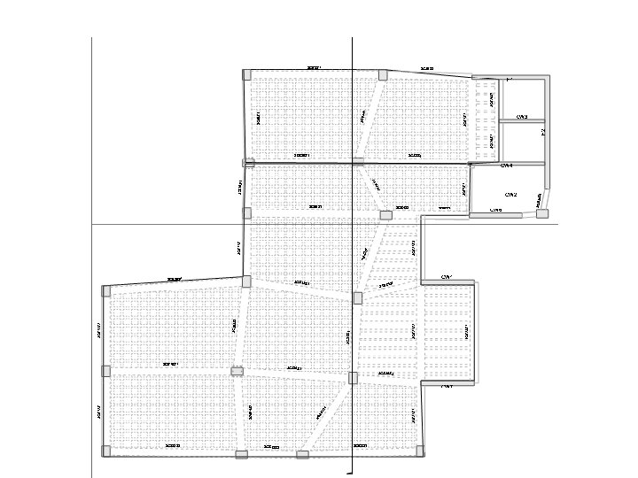
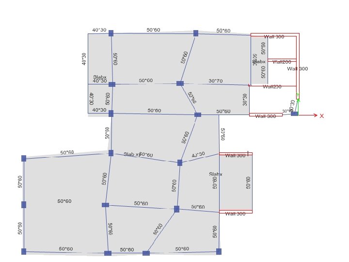
Structural Design The medical center 4 floors are made completely of reinforced concrete.
Structural Design ØCodes and Standards: q ACI -318 -11 for reinforced concrete structural design. q UBC -97 for earthquake design. q ASCE 7 2010 for load combinations q For the design of the structure and its elements ETABS , SAP and hand calculations were used.
Structural Design
Structural Design ØDesign data: q Concrete strength, f’c=24 MPa. q Steel yield strength fy=420 MPa. q Bearing capacity for soil = 250 k. N/m 2
Structural Design • Vertical Loads: • Live Load (k. N/m 2) 4 k. N / m 2 • SID ( k. N /m 2) 6 k. N / m 2
Structural Design q Seismic Design data : q The city of structure is talfet. q The seismic zone factor. Z=0. 2. q The soil profile is type Sd. q The acceleration coefficient Ca=0. 28 seismic q The velocity seismic coefficient Cv=0. 4. q The Seismic importance factor is 1. 25 q The structural design type is intermediate, R=5. 5
Modeling
Sections Dimensions Structural Element Dimensions Ribbed Slab 30 cm thickness Columns (70 X 30) and ( 70 X 50) Beams ( 50 X 60) , ( 40 X 30 ) , ( 30 X 30 )
Verification of the model q. Compatibility check q. Equilibrium check q. Stress – strain (local check)
Verification of the model • Compatibility check
Verification of the model • Equilibrium Check
Verification of the model • Stress- strain (local check)
Design checks
Slab Reinforcement
Beams Reinforcement
Columns Reinforcement
Footing Reinforcement
Shear Wall Reinforcement
Stair Reinforcement
Ø Mechanical design: • • Water supply. Drainage. HVAC. Firing system.
Water supply design: (left part) Water consumption in medical center is 5 L/PERSON : #floor/fixture Wc Lavatory Kitchen sink Basement 9 13 0 Ground floor 9 17 0 1 st floor 9 19 4 2 nd floor 9 14 2 Total 36 63 6
Water supply design: (right part)
Ø distribution of water supply
Ø drainage system design :
Layout for drainage in all building:
Drainage system for the rainwater
ØHVAC design: VRF system is chosen to be used. All of the components are chosen from (Toshiba) and they are shown as follows: üMain unit (outdoor unit) üController üThe indoor unit
Components
ØHVAC Room Volumetric flow rate (m 3/s) # of diffusers Emergency (G. F) 0. 2591 2 Waiting ( first floor) 0. 6005 4 Lab ( second floor) 0. 3318 2
Ø Electrical design:
Ø Electrical design:
Ø Electrical design:
Ø Electrical design: Visual glare area Max = 15. 1 <19 ok glare description
Electrical design:
Electrical design:
Electrical design:
Ø Fire and safety: Warning signs
. : . Ø Fire and safety: Dry and Wet Chemical Extinguishers Multi-purpose -Dry Chemical Extinguisher CO 2 or Dry Chemical and Carbon Dioxide Extinguisher Sprinkler
Ø Fire and safety:
ØReflecting ceiling :
Ø Quantity and surveying Total unit cost = 1750 NIS/M^2