
Tel Aviv University Electrical Discharge and Plasma Laboratory
Tel Aviv University Electrical Discharge and Plasma Laboratory Depart of Electrical Engineering - Physical Electronics Experimental Study of Vacuum Arcs with Refractory Anodes I. I. Beilis and R. L. Boxman Me. VARC-5 2015 1
Outline • Vacuum arc-refractory anode: – Conventional vacuum arc – Open cylindrical electrode configuration, HRAVA – Closed electrode configuration, “Black Body” • Measurements. – a) Electrode effective voltage – b) Anode temperature – c) ion current – d) Thin film deposition • Summary Me. VARC-5 2015 2

Conventional vacuum arc V- Arc is low voltage discharge 20 -30 V’s Cathode spot, jet: Water Cathode (MP) • Current supported by cathode spots - electron emission and cathode heating Jet • High local evaporation rate and dense Spot plasma and MP’s generation Ring Anode • Supersonic, fully ionized, high kinetic energy 20 -150 e. V plasma jet generation • Different applications including vacuum arc deposition Effective cathode voltage. Experiment: Ucef=6. 2 V- Daalder, 1977 (100 A) Definition: Ucef [V]=Q/I 8 V – Reece, 1963 (30 A) Q –cathode heat flux [W], I [A] Theory: Ucef=8 V- Beilis, High Temp. 1977 Me. VARC-5 2015 3
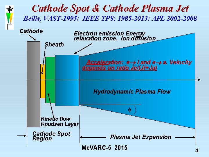
Cathode Spot & Cathode Plasma Jet Beilis, VAST-1995; IEEE TPS: 1985 -2013: APL 2002 -2008 Cathode Sheath Electron emission Energy relaxation zone. Ion diffusion Acceleration: e i and e a. Velocity depends on ratio Je/(Ji+Ja) Hydrodynamic Plasma Flow Kinetic flow Knudsen Layer Cathode Spot Region Plasma Jet Expansion Me. VARC-5 2015 4

Macroparticle – Plasma cleaning Magnetic Filtered Vacuum Arc Deposition Methods Method Material Rate, µm/min PVD (Magnetron sputtering) IPVD (Ionized PVD) Ti Al on Si. O 2 0. 017 0. 01 CVD Cu on Ti. N Cu on Si wafer 0. 05 -0. 2 0. 05 -0. 1 PACVD (Plasma assisted) Cu on Si. O 2, Al 0. 004 -0. 02 SSMD (Self Sputtering) Cu on Si wafer 0. 02 -0. 4 Electroless Cu on Si wafer 0. 1 -0. 16 Magnetic Filtered Vacuum Arc Deposition Cu on glass 0. 1 Disadvantages: • Usually low efficiency of material utilization • Me. VARC-5 2015 Complex equipment 5

Vacuum arc with Refractory Anode HRAVA development Hot Refractory Anode Vacuum Arc (HRAVA): Vacuum Arc with Black Body Assembly (VABBA): One hole Anode: Shower Anode: MP Me. VARC-5 2015 6

Vacuum arc with Refractory Anode Conditions Water cooled Cathode, Gr, Cu, Cr, Ti VABBA-Anode HRAVA Anode A-C distance Anode thickness Arc current, I Arc time, t Length: 40 mm; Diameter: D=30 mm Experimental methodology Length: 22 mm; D=50 mm, W-250 holes (D=1 mm) Ta-1 hole, D=4 mm v calorimetric test, W, Mo h=5 -10 mm 5, 10, 20, 30 mm 150, 175, 200, 225, 250 A ~180 s W-Thermocouple T-Thermocouple K-type (chromel-alumel) W/5%Re-W/26%Re Water flow rate, F 0. 193, 0. 29 L/s Ion Probe Plasma probe v Thermocouple v Optical Microscopy, SEM v Photography v Electrical probe v Profilometry W rod 1. 5 mm diameter, Vbias=-20 V Chamber-total current Me. VARC-5 2015 7
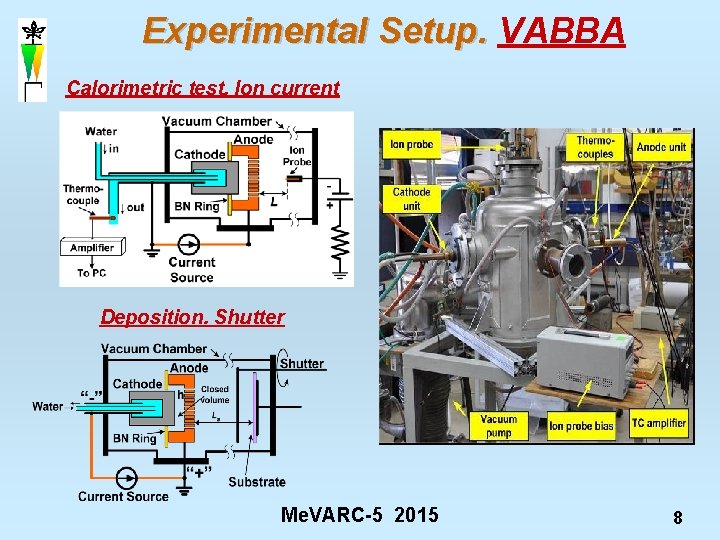
Experimental Setup. VABBA Calorimetric test. Ion current Deposition. Shutter Me. VARC-5 2015 8

HRAVA plasma. Effective cathode (Cu) & anode (Gr) voltages (t>60 s) Cathode: Ucef~7 V Anode: Uaef~ 11 -12 V (t<10 s) 6. 5 V (t>60 s) Jet energy IUj =anode+ surrounding! (t>60 s) Rosenthal, Beilis, Goldsmith, Boxman, JPhys. D 1995 Beilis, Goldsmith, Boxman, Po. P 2000 and 2002 Me. VARC-5 2015 9

VABBA plasma and effective cathode voltage Shower W Anode, 250 holes-1 mm: One hole (4 mm) Ta Anode: Me. VARC-5 2015 10

Ucef (VABBA)=11 -12 V 1) consists of: Ucef = 6. 5 V (conventional from the spot) and 2) part of returned plasma jet energy Uj (12 V) that not expands to surroundings and remains in the closed electrode configuration! IEEE Trans. Plasma Sci. , 41, N 8, Part II, 1992, 2013 Me. VARC-5 2015 11
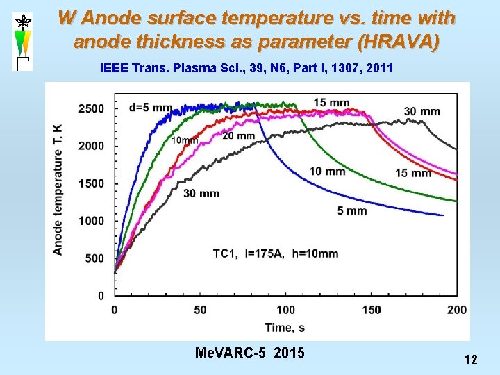
W Anode surface temperature vs. time with anode thickness as parameter (HRAVA) IEEE Trans. Plasma Sci. , 39, N 6, Part I, 1307, 2011 Me. VARC-5 2015 12
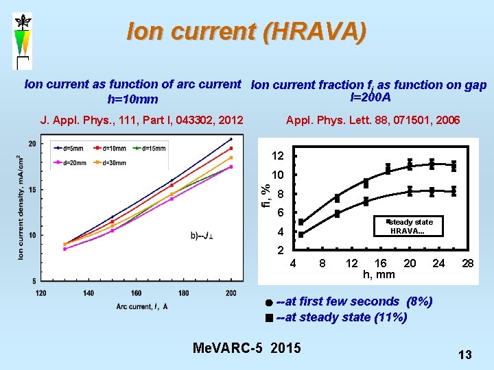
Ion current (HRAVA) Ion current as function of arc current Ion current fraction fi as function on gap I=200 A h=10 mm Appl. Phys. Lett. 88, 071501, 2006 J. Appl. Phys. , 111, Part I, 043302, 2012 12 fi, % 10 8 6 steady state HRAVA. . . 4 2 4 8 12 16 20 h, mm 24 28 --at first few seconds (8%) --at steady state (11%) Me. VARC-5 2015 13
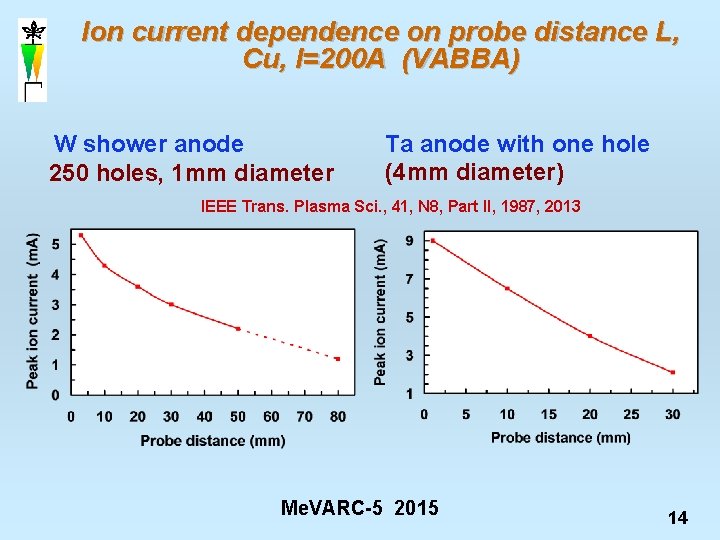
Ion current dependence on probe distance L, Cu, I=200 A (VABBA) W shower anode 250 holes, 1 mm diameter Ta anode with one hole (4 mm diameter) IEEE Trans. Plasma Sci. , 41, N 8, Part II, 1987, 2013 Me. VARC-5 2015 14
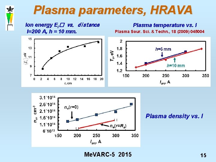
Plasma parameters, HRAVA Ion energy Ei� vs. distance I=200 A, h = 10 mm. Plasma temperature vs. I Plasma Sour. Sci. & Techn. , 18 (2009) 045004 Plasma density vs. I Me. VARC-5 2015 15
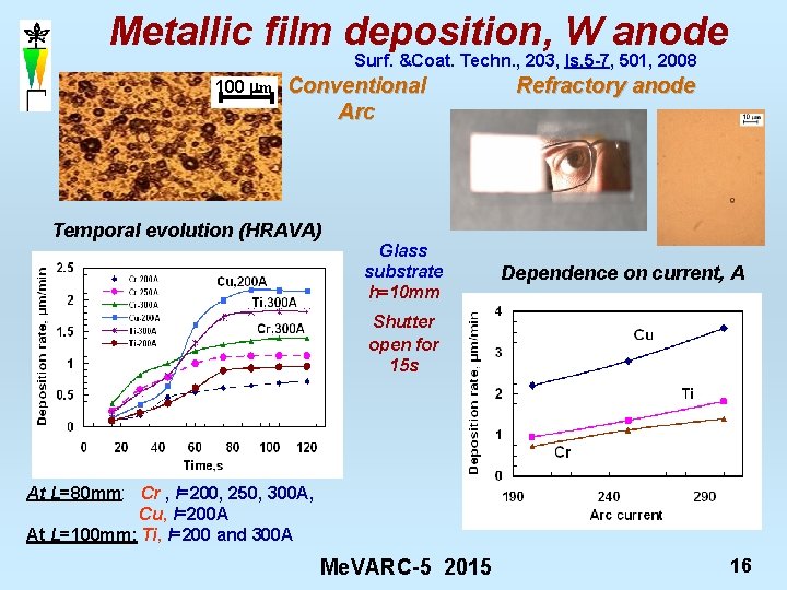
Metallic film deposition, W anode Surf. &Coat. Techn. , 203, Is. 5 -7, 501, 2008 100 mm Conventional Arc Temporal evolution (HRAVA) Glass substrate h=10 mm Refractory anode Dependence on current, A Shutter open for 15 s At L=80 mm: Cr , I=200, 250, 300 A, Cu, I=200 A At L=100 mm: Ti, I=200 and 300 A Me. VARC-5 2015 16
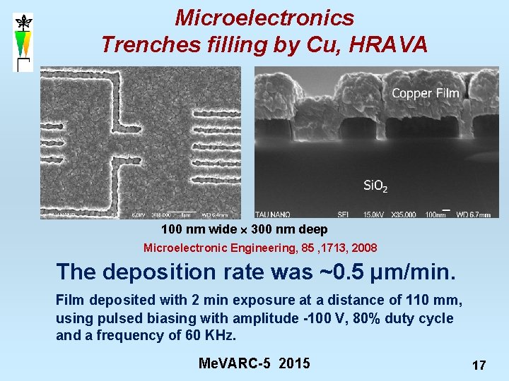
Microelectronics Trenches filling by Cu, HRAVA 100 nm wide 300 nm deep Microelectronic Engineering, 85 , 1713, 2008 The deposition rate was ~0. 5 µm/min. Film deposited with 2 min exposure at a distance of 110 mm, using pulsed biasing with amplitude -100 V, 80% duty cycle and a frequency of 60 KHz. Me. VARC-5 2015 17
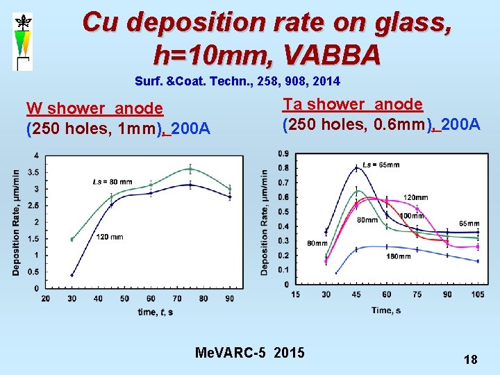
Cu deposition rate on glass, h=10 mm, VABBA Surf. &Coat. Techn. , 258, 908, 2014 W shower anode (250 holes, 1 mm), 200 A Ta shower anode (250 holes, 0. 6 mm), 200 A Me. VARC-5 2015 18
SUMMARY v The refractory anode arc characterized by plasma plume expanding radially (HRAVA) or directly (VABBA). Plasma – is the cathode material! v Cathode Ucef in VABBA increases to ~6. 5 V for cold anodes (like conventional cathodic arc) & then to steady state of ~11 -12 V after anode is heated v The ion flux fraction (12%) in arc with refractory anode was larger in comparison to conventional arc (8%) v Plasma temperature was Te~1. 3 -1. 8 e. V, density>1014 cm-3, and plasma was accelerated up to ~15 e. V during its expansion. v The arc is a simple metallic plasma source for coatings. The high efficiency is determined by MP’s conversion into plasma v Steady-state HRAVA deposition rate reach 3. 6(Cu), 1. 8(Ti) and 1. 4µm/min (Cr) for I=300 A, while PVD, CVD, FVAD showed about 0. 1µm/min (Review: Surf. & Coat. Techn. , 204, N 6 -7, 865, 2009). Me. VARC-5 2015 19
Thanks to our colleagues: • Samuel Goldsmith • Michael Keidar • Alexey Shashurin • David Arbilly • Arye Snaiderman • Dmitry Grach. • Yosef Koulik Thank You Me. VARC-5 2015 20
- Slides: 20