
Pusan National University Data Communications Chapter 4 Digital
- Slides: 45
Pusan National University Data Communications Chapter 4 Digital Transmission School of Computer Science and Engineering Pusan National University Jeong Goo Kim
세계로 미래로 power PNU Ch. 4 Outline 4. 1 Digital-to-Digital Conversion 4. 2 Analog-to-digital 4. 3 Transmission Modes Advanced Broadcasting & Communications Lab. 2
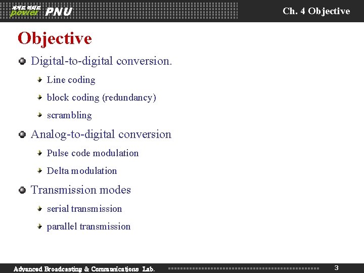
세계로 미래로 power PNU Ch. 4 Objective Digital-to-digital conversion. Line coding block coding (redundancy) scrambling Analog-to-digital conversion Pulse code modulation Delta modulation Transmission modes serial transmission parallel transmission Advanced Broadcasting & Communications Lab. 3
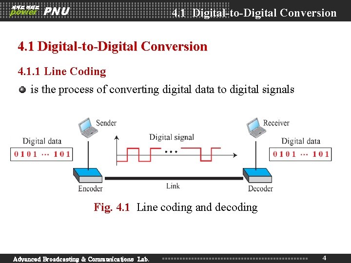
세계로 미래로 power PNU 4. 1 Digital-to-Digital Conversion 4. 1. 1 Line Coding is the process of converting digital data to digital signals Fig. 4. 1 Line coding and decoding Advanced Broadcasting & Communications Lab. 4
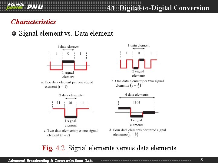
세계로 미래로 power PNU 4. 1 Digital-to-Digital Conversion Characteristics Signal element vs. Data element Fig. 4. 2 Signal elements versus data elements Advanced Broadcasting & Communications Lab. 5
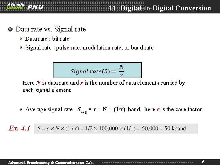
세계로 미래로 power PNU 4. 1 Digital-to-Digital Conversion Data rate vs. Signal rate Data rate : bit rate Signal rate : pulse rate, modulation rate, or baud rate Here N is data rate and r is the number of data elements carried by each signal element Average signal rate Savg = c × N × (1/r) baud, here c is the case factor Ex. 4. 1 Advanced Broadcasting & Communications Lab. 6
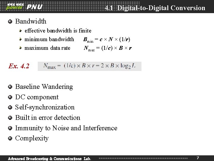
세계로 미래로 power PNU 4. 1 Digital-to-Digital Conversion Bandwidth effective bandwidth is finite minimum bandwidth Bmin = c × N × (1/r) maximum data rate Nmax = (1/c) × B × r Ex. 4. 2 Baseline Wandering DC component Self-synchronization Built in error detection Immunity to Noise and Interference Complexity Advanced Broadcasting & Communications Lab. 7
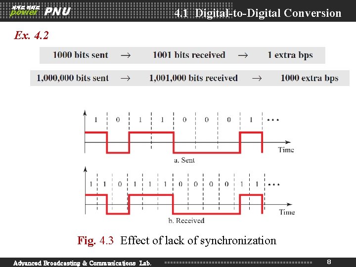
세계로 미래로 power PNU 4. 1 Digital-to-Digital Conversion Ex. 4. 2 Fig. 4. 3 Effect of lack of synchronization Advanced Broadcasting & Communications Lab. 8
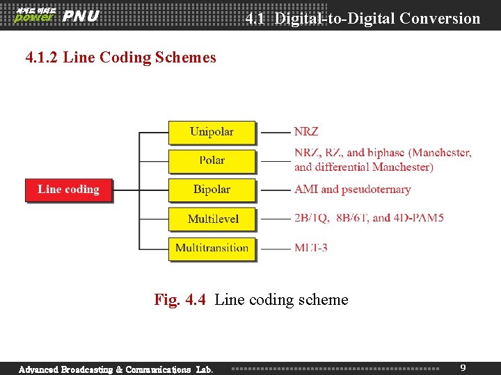
세계로 미래로 power PNU 4. 1 Digital-to-Digital Conversion 4. 1. 2 Line Coding Schemes Fig. 4. 4 Line coding scheme Advanced Broadcasting & Communications Lab. 9
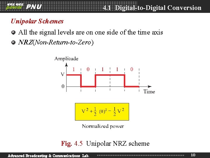
세계로 미래로 power PNU 4. 1 Digital-to-Digital Conversion Unipolar Schemes All the signal levels are on one side of the time axis NRZ(Non-Return-to-Zero) Fig. 4. 5 Unipolar NRZ scheme Advanced Broadcasting & Communications Lab. 10
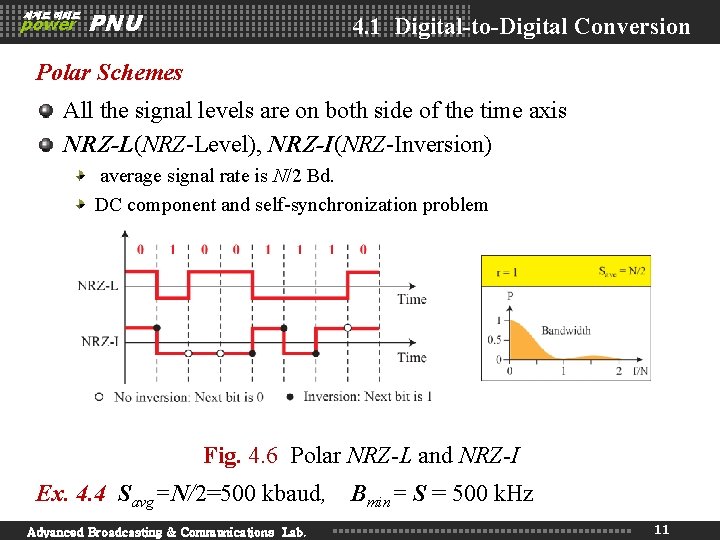
세계로 미래로 power PNU 4. 1 Digital-to-Digital Conversion Polar Schemes All the signal levels are on both side of the time axis NRZ-L(NRZ-Level), NRZ-I(NRZ-Inversion) average signal rate is N/2 Bd. DC component and self-synchronization problem Fig. 4. 6 Polar NRZ-L and NRZ-I Ex. 4. 4 Savg=N/2=500 kbaud, Advanced Broadcasting & Communications Lab. Bmin= S = 500 k. Hz 11
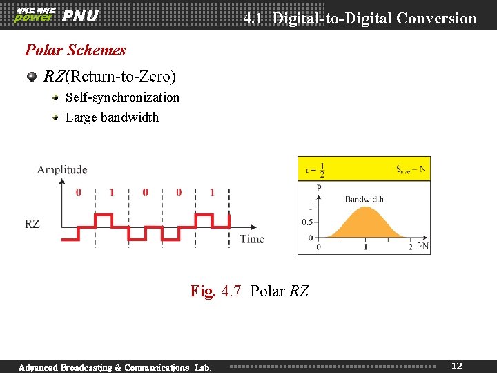
세계로 미래로 power PNU 4. 1 Digital-to-Digital Conversion Polar Schemes RZ(Return-to-Zero) Self-synchronization Large bandwidth Fig. 4. 7 Polar RZ Advanced Broadcasting & Communications Lab. 12
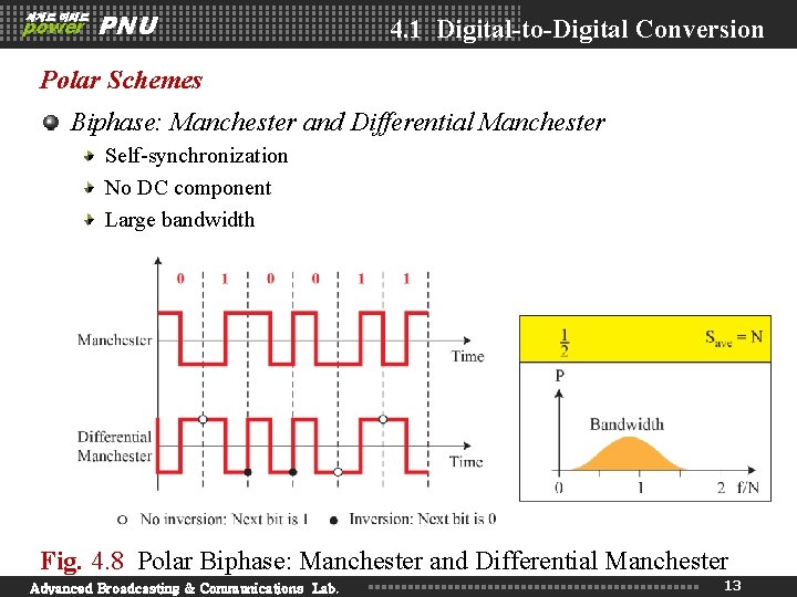
세계로 미래로 power PNU 4. 1 Digital-to-Digital Conversion Polar Schemes Biphase: Manchester and Differential Manchester Self-synchronization No DC component Large bandwidth Fig. 4. 8 Polar Biphase: Manchester and Differential Manchester Advanced Broadcasting & Communications Lab. 13
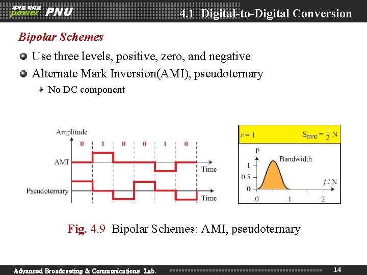
세계로 미래로 power PNU 4. 1 Digital-to-Digital Conversion Bipolar Schemes Use three levels, positive, zero, and negative Alternate Mark Inversion(AMI), pseudoternary No DC component Fig. 4. 9 Bipolar Schemes: AMI, pseudoternary Advanced Broadcasting & Communications Lab. 14
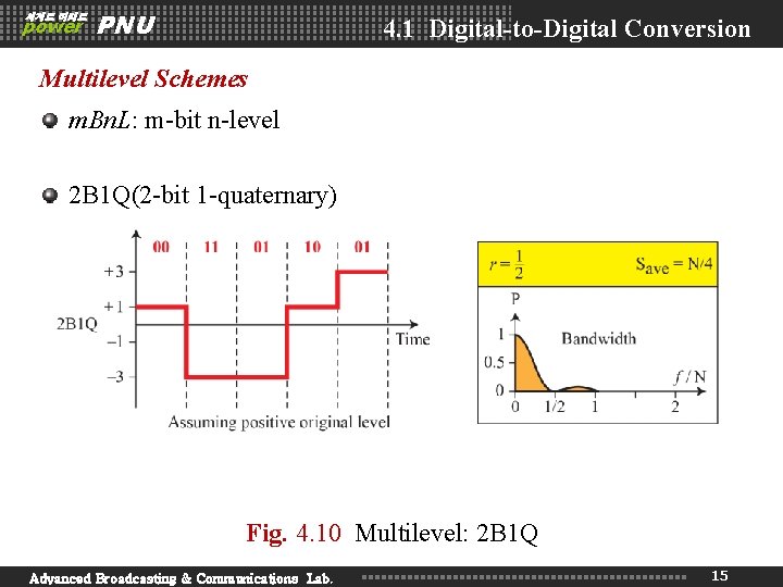
세계로 미래로 power PNU 4. 1 Digital-to-Digital Conversion Multilevel Schemes m. Bn. L: m-bit n-level 2 B 1 Q(2 -bit 1 -quaternary) Fig. 4. 10 Multilevel: 2 B 1 Q Advanced Broadcasting & Communications Lab. 15
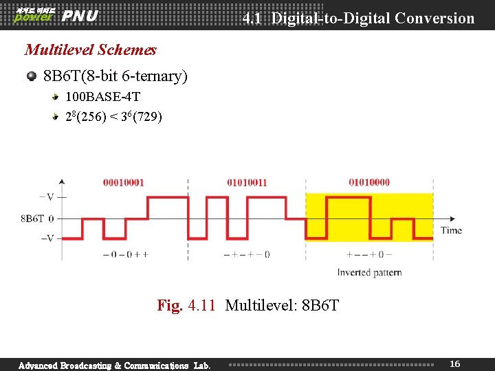
세계로 미래로 power PNU 4. 1 Digital-to-Digital Conversion Multilevel Schemes 8 B 6 T(8 -bit 6 -ternary) 100 BASE-4 T 28(256) < 36(729) Fig. 4. 11 Multilevel: 8 B 6 T Advanced Broadcasting & Communications Lab. 16
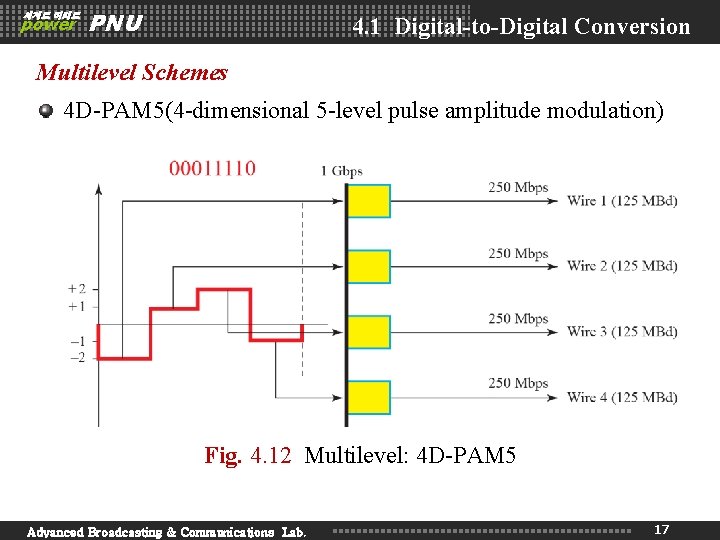
세계로 미래로 power PNU 4. 1 Digital-to-Digital Conversion Multilevel Schemes 4 D-PAM 5(4 -dimensional 5 -level pulse amplitude modulation) Fig. 4. 12 Multilevel: 4 D-PAM 5 Advanced Broadcasting & Communications Lab. 17
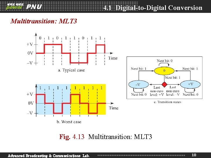
세계로 미래로 power PNU 4. 1 Digital-to-Digital Conversion Multitransition: MLT 3 Fig. 4. 13 Multitransition: MLT 3 Advanced Broadcasting & Communications Lab. 18
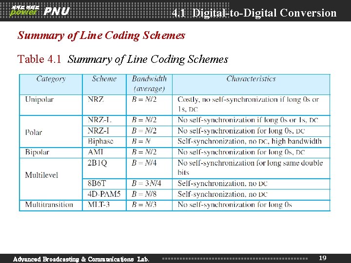
세계로 미래로 power PNU 4. 1 Digital-to-Digital Conversion Summary of Line Coding Schemes Table 4. 1 Summary of Line Coding Schemes Advanced Broadcasting & Communications Lab. 19
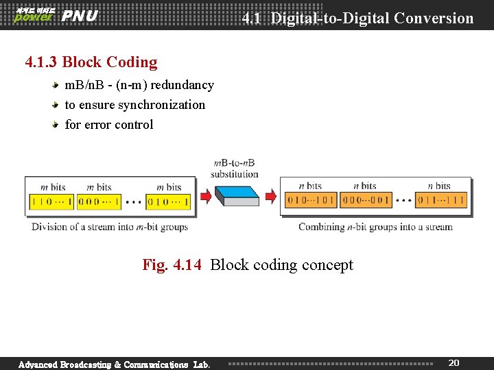
세계로 미래로 power PNU 4. 1 Digital-to-Digital Conversion 4. 1. 3 Block Coding m. B/n. B - (n-m) redundancy to ensure synchronization for error control Fig. 4. 14 Block coding concept Advanced Broadcasting & Communications Lab. 20
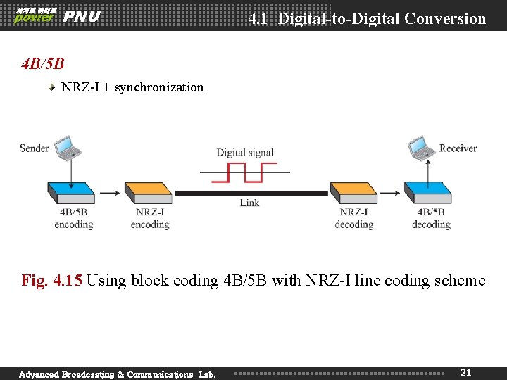
세계로 미래로 power PNU 4. 1 Digital-to-Digital Conversion 4 B/5 B NRZ-I + synchronization Fig. 4. 15 Using block coding 4 B/5 B with NRZ-I line coding scheme Advanced Broadcasting & Communications Lab. 21
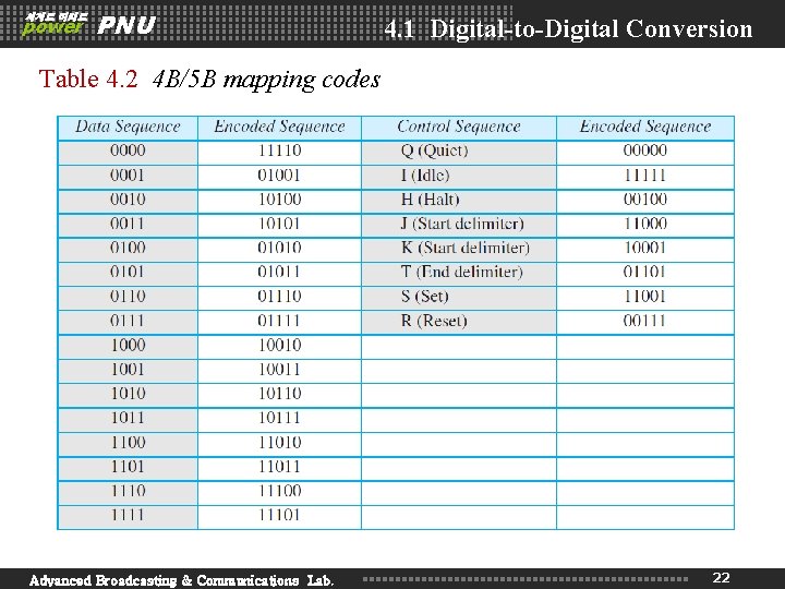
세계로 미래로 power PNU 4. 1 Digital-to-Digital Conversion Table 4. 2 4 B/5 B mapping codes Advanced Broadcasting & Communications Lab. 22
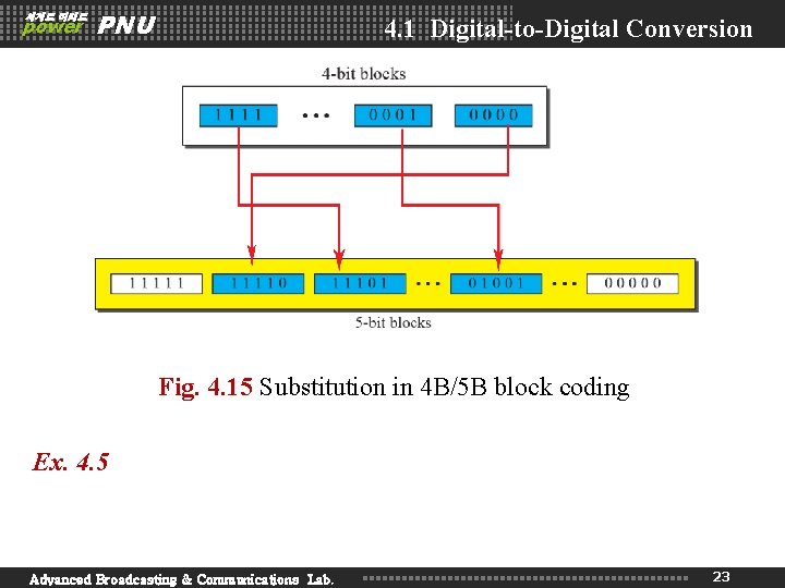
세계로 미래로 power PNU 4. 1 Digital-to-Digital Conversion Fig. 4. 15 Substitution in 4 B/5 B block coding Ex. 4. 5 Advanced Broadcasting & Communications Lab. 23
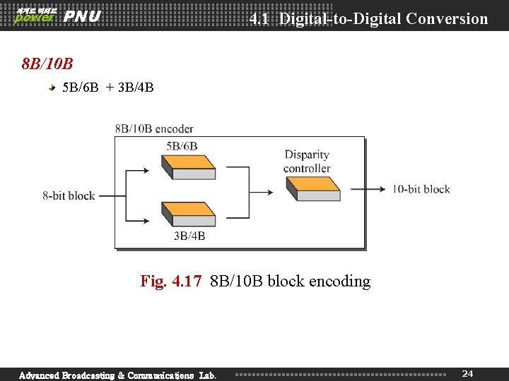
세계로 미래로 power PNU 4. 1 Digital-to-Digital Conversion 8 B/10 B 5 B/6 B + 3 B/4 B Fig. 4. 17 8 B/10 B block encoding Advanced Broadcasting & Communications Lab. 24
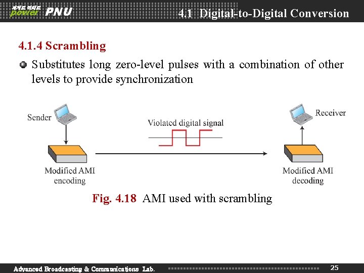
세계로 미래로 power PNU 4. 1 Digital-to-Digital Conversion 4. 1. 4 Scrambling Substitutes long zero-level pulses with a combination of other levels to provide synchronization Fig. 4. 18 AMI used with scrambling Advanced Broadcasting & Communications Lab. 25
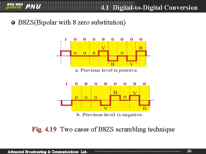
세계로 미래로 power PNU 4. 1 Digital-to-Digital Conversion B 8 ZS(Bipolar with 8 zero substitution) Fig. 4. 19 Two cases of B 8 ZS scrambling technique Advanced Broadcasting & Communications Lab. 26
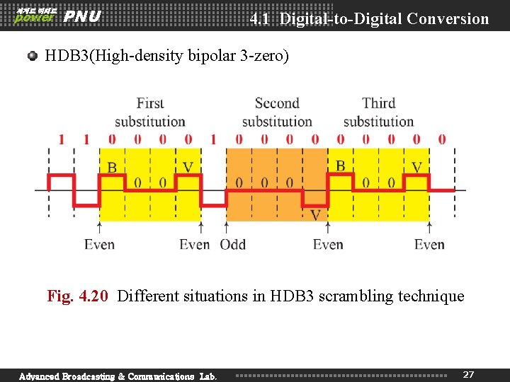
세계로 미래로 power PNU 4. 1 Digital-to-Digital Conversion HDB 3(High-density bipolar 3 -zero) Fig. 4. 20 Different situations in HDB 3 scrambling technique Advanced Broadcasting & Communications Lab. 27
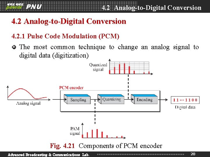
세계로 미래로 power PNU 4. 2 Analog-to-Digital Conversion 4. 2. 1 Pulse Code Modulation (PCM) The most common technique to change an analog signal to digital data (digitization) Fig. 4. 21 Components of PCM encoder Advanced Broadcasting & Communications Lab. 28
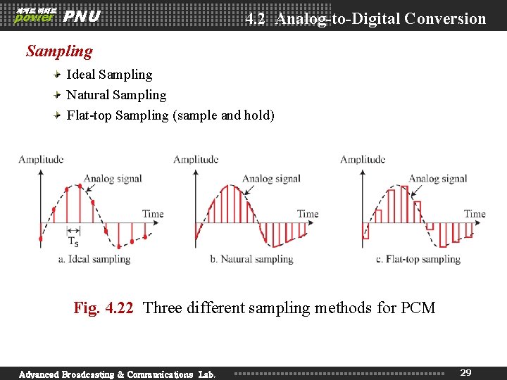
세계로 미래로 power PNU 4. 2 Analog-to-Digital Conversion Sampling Ideal Sampling Natural Sampling Flat-top Sampling (sample and hold) Fig. 4. 22 Three different sampling methods for PCM Advanced Broadcasting & Communications Lab. 29
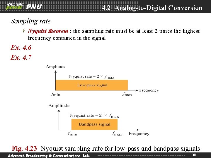
세계로 미래로 power PNU 4. 2 Analog-to-Digital Conversion Sampling rate Nyquist theorem : the sampling rate must be at least 2 times the highest frequency contained in the signal Ex. 4. 6 Ex. 4. 7 Fig. 4. 23 Nyquist sampling rate for low-pass and bandpass signals Advanced Broadcasting & Communications Lab. 30
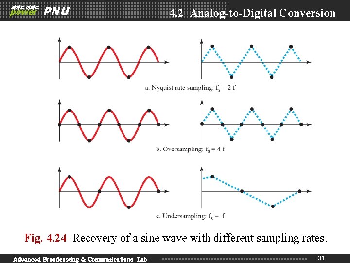
세계로 미래로 power PNU 4. 2 Analog-to-Digital Conversion Fig. 4. 24 Recovery of a sine wave with different sampling rates. Advanced Broadcasting & Communications Lab. 31
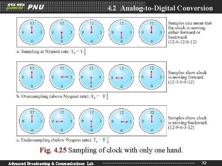
세계로 미래로 power PNU 4. 2 Analog-to-Digital Conversion Fig. 4. 25 Sampling of clock with only one hand. Advanced Broadcasting & Communications Lab. 32
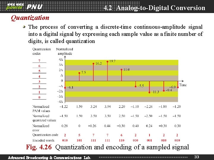
세계로 미래로 power PNU 4. 2 Analog-to-Digital Conversion Quantization The process of converting a discrete-time continuous-amplitude signal into a digital signal by expressing each sample value as a finite number of digits, is called quantization Fig. 4. 26 Quantization and encoding of a sampled signal Advanced Broadcasting & Communications Lab. 33
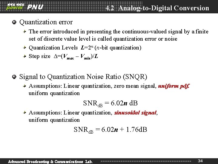
세계로 미래로 power PNU 4. 2 Analog-to-Digital Conversion Quantization error The error introduced in presenting the continuous-valued signal by a finite set of discrete value level is called quantization error or noise Quantization Levels L=2 n (n-bit quantization) Step size Δ=(Vmax – Vmin)/L Signal to Quantization Noise Ratio (SNQR) Assumptions: Linear quantization, zero mean signal, uniform pdf. uniform quantization SNRd. B = 6. 02 n d. B Assumptions: Linear quantization, sinusoidal signal, uniform quantization SNRd. B = 6. 02 n + 1. 76 d. B Advanced Broadcasting & Communications Lab. 34
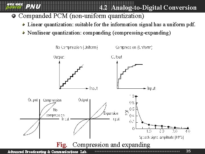
PNU 4. 2 Analog-to-Digital Conversion Companded PCM (non-uniform quantization) 세계로 미래로 power Linear quantization: suitable for the information signal has a uniform pdf. Nonlinear quantization: companding (compressing-expanding) Fig. Compression and expanding Advanced Broadcasting & Communications Lab. 35
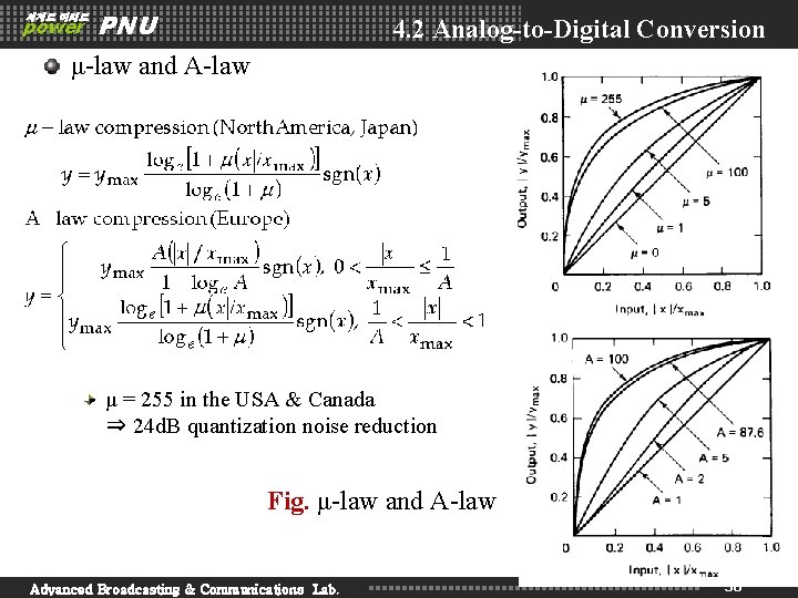
세계로 미래로 power PNU 4. 2 Analog-to-Digital Conversion μ-law and A-law μ = 255 in the USA & Canada ⇒ 24 d. B quantization noise reduction Fig. μ-law and A-law Advanced Broadcasting & Communications Lab. 36
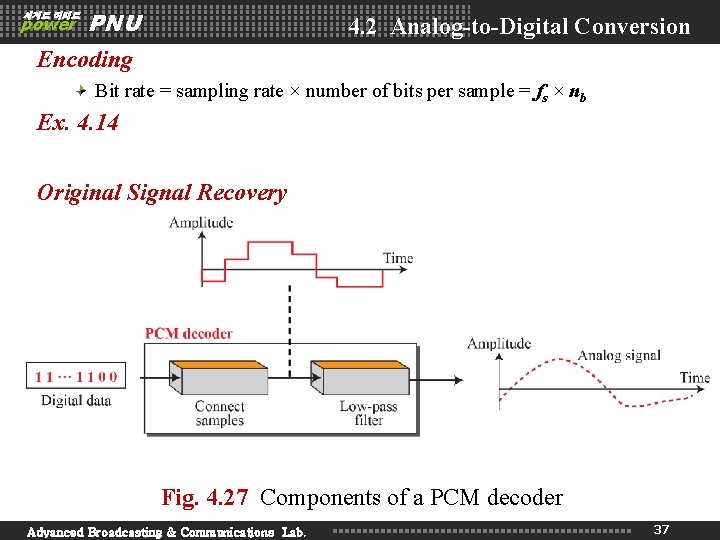
세계로 미래로 power PNU 4. 2 Analog-to-Digital Conversion Encoding Bit rate = sampling rate × number of bits per sample = fs × nb Ex. 4. 14 Original Signal Recovery Fig. 4. 27 Components of a PCM decoder Advanced Broadcasting & Communications Lab. 37
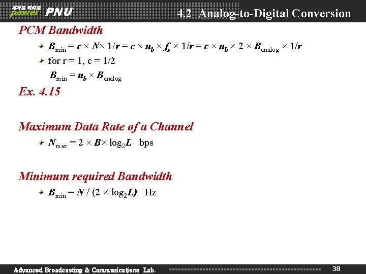
세계로 미래로 power PNU 4. 2 Analog-to-Digital Conversion PCM Bandwidth Bmin = c × N× 1/r = c × nb × fs × 1/r = c × nb × 2 × Banalog × 1/r for r = 1, c = 1/2 Bmin = nb × Banalog Ex. 4. 15 Maximum Data Rate of a Channel Nmax = 2 × B× log 2 L bps Minimum required Bandwidth Bmin = N / (2 × log 2 L) Hz Advanced Broadcasting & Communications Lab. 38
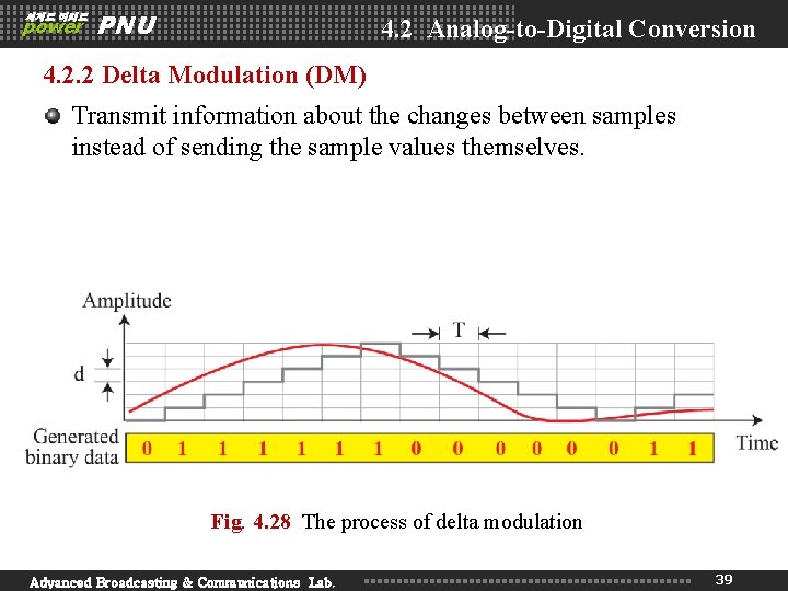
세계로 미래로 power PNU 4. 2 Analog-to-Digital Conversion 4. 2. 2 Delta Modulation (DM) Transmit information about the changes between samples instead of sending the sample values themselves. Fig. 4. 28 The process of delta modulation Advanced Broadcasting & Communications Lab. 39
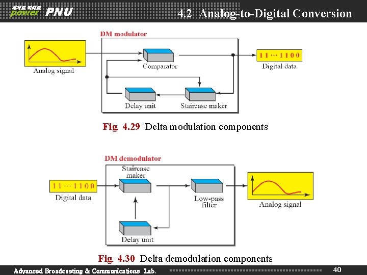
세계로 미래로 power PNU 4. 2 Analog-to-Digital Conversion Fig. 4. 29 Delta modulation components Fig. 4. 30 Delta demodulation components Advanced Broadcasting & Communications Lab. 40
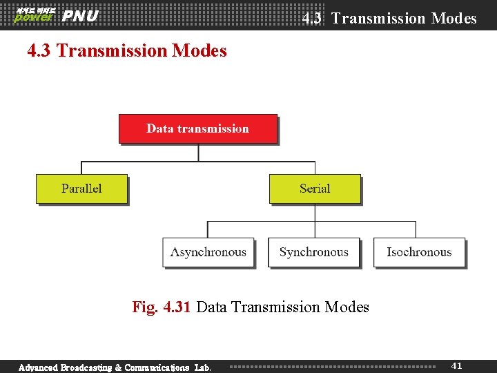
세계로 미래로 power PNU 4. 3 Transmission Modes Fig. 4. 31 Data Transmission Modes Advanced Broadcasting & Communications Lab. 41
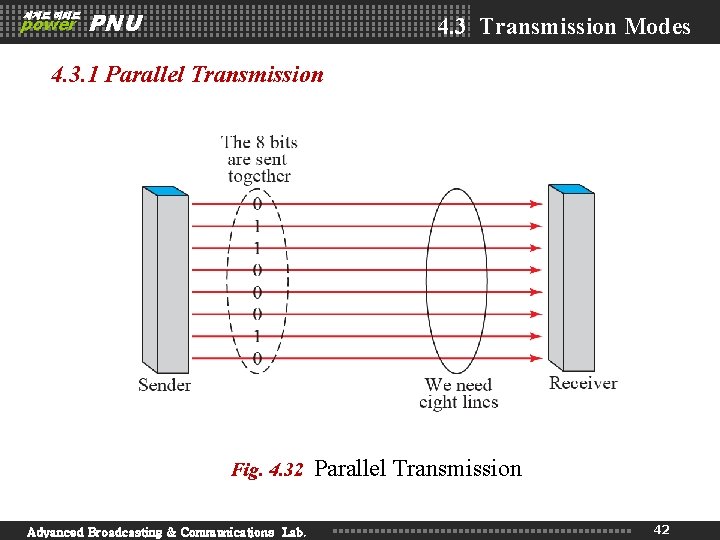
세계로 미래로 power PNU 4. 3 Transmission Modes 4. 3. 1 Parallel Transmission Fig. 4. 32 Advanced Broadcasting & Communications Lab. Parallel Transmission 42
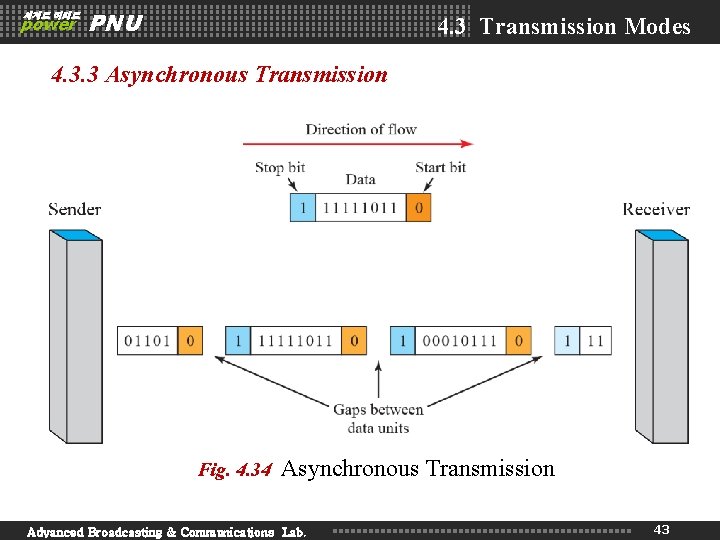
세계로 미래로 power PNU 4. 3 Transmission Modes 4. 3. 3 Asynchronous Transmission Fig. 4. 34 Asynchronous Transmission Advanced Broadcasting & Communications Lab. 43
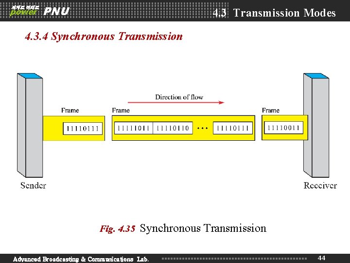
세계로 미래로 power PNU 4. 3 Transmission Modes 4. 3. 4 Synchronous Transmission Fig. 4. 35 Synchronous Transmission Advanced Broadcasting & Communications Lab. 44
세계로 미래로 power PNU Homework Read textbook pp. 135 -150 Next Lecture Chapter 5. Analog Transmission Advanced Broadcasting & Communications Lab. 45