Verilog HDL n 1 2 3 4 Verilog


; parameter size = 8; input [size:")
 begin $display")


; input en, d; output q; reg")

 scan_reg. q ; initial begin #10 force scan_reg. q =")
![Verilog HDL 数字系统设计 reg[2: 0] Colt; . . . Colt = 2; force Colt](https://slidetodoc.com/presentation_image_h2/892e3fa6c7438c569df3f9923592786e/image-24.jpg "Verilog HDL 数字系统设计 reg[2: 0] Colt; . . . Colt = 2; force Colt")
![Verilog HDL 数字系统设计 module Interacting (Serial_In, Clk, Parallel_Out); input Serial_In, Clk; output [0: 7]](https://slidetodoc.com/presentation_image_h2/892e3fa6c7438c569df3f9923592786e/image-27.jpg "Verilog HDL 数字系统设计 module Interacting (Serial_In, Clk, Parallel_Out); input Serial_In, Clk; output [0: 7]")
 ; / *任务Read_Word在每个时钟周期 读取串行数据,将其转换为并行 数据并存于Data中。*/")
; input d,")
 Port declarations (if ports are")
![Verilog HDL 数字系统设计 端口说明 module Micro (PC, Instr, Next. Addr ); input [3: 1]](https://slidetodoc.com/presentation_image_h2/892e3fa6c7438c569df3f9923592786e/image-35.jpg "Verilog HDL 数字系统设计 端口说明 module Micro (PC, Instr, Next. Addr ); input [3: 1]")
; input A")
![Verilog HDL 数字系统设计 module Child(Pba, Ppy) ; input [5: 0] Pba; output [2: 0]](https://slidetodoc.com/presentation_image_h2/892e3fa6c7438c569df3f9923592786e/image-43.jpg "Verilog HDL 数字系统设计 module Child(Pba, Ppy) ; input [5: 0] Pba; output [2: 0]")
; output fco, fsum; input")
; output fco, fsum; input")
![Verilog HDL 数字系统设计 外部端口 n 外部可见的模块端口 module Scram_A(Arb, Ctrl, Mem_Blk, Byte); input[0: 3] Arb;](https://slidetodoc.com/presentation_image_h2/892e3fa6c7438c569df3f9923592786e/image-49.jpg "Verilog HDL 数字系统设计 外部端口 n 外部可见的模块端口 module Scram_A(Arb, Ctrl, Mem_Blk, Byte); input[0: 3] Arb;")
")
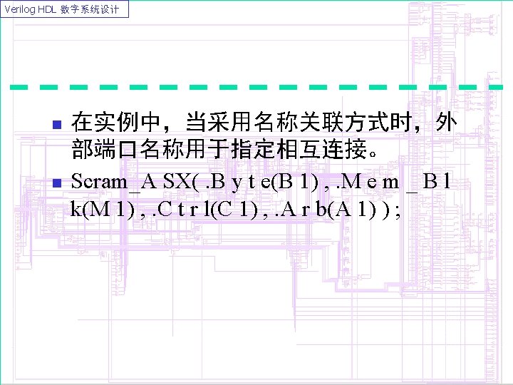
 , . Control(Ctrl) , . Mem_Word(Mem_Blk) ,")
![Verilog HDL 数字系统设计 module Scram_C (Arb[0: 2] , Ctrl, {Mem_Blk[0] , Mem_Blk[1]} , Byte[3]](https://slidetodoc.com/presentation_image_h2/892e3fa6c7438c569df3f9923592786e/image-56.jpg "Verilog HDL 数字系统设计 module Scram_C (Arb[0: 2] , Ctrl, {Mem_Blk[0] , Mem_Blk[1]} , Byte[3]")
![Verilog HDL 数字系统设计 module Scram_D (. Data(Arb[0: 2]), . Control(Ctrl), . Mem_Word({Mem_Blk[0], Mem_Blk[1]}), .](https://slidetodoc.com/presentation_image_h2/892e3fa6c7438c569df3f9923592786e/image-58.jpg "Verilog HDL 数字系统设计 module Scram_D (. Data(Arb[0: 2]), . Control(Ctrl), . Mem_Word({Mem_Blk[0], Mem_Blk[1]}), .")
 , .")
![Verilog HDL 数字系统设计 结构模型描述十进制计数器 module Decade_Ctr (Clock, Z) ; input Clock; output [0: 3]](https://slidetodoc.com/presentation_image_h2/892e3fa6c7438c569df3f9923592786e/image-62.jpg "Verilog HDL 数字系统设计 结构模型描述十进制计数器 module Decade_Ctr (Clock, Z) ; input Clock; output [0: 3]")
 ; input Clk, Cnt_Up, Cnt_Down;")
- Slides: 63
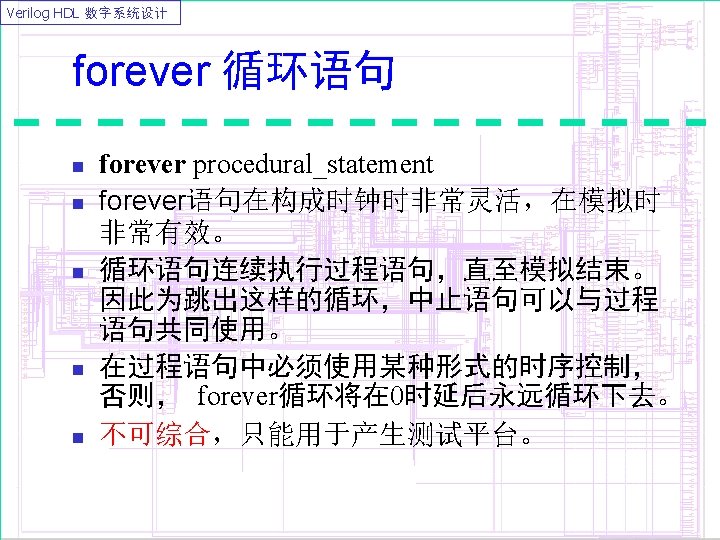
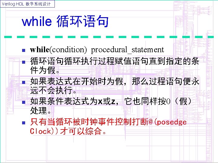
Verilog HDL 数字系统设计 循环语句 n 1. 2. 3. 4. Verilog HDL中有四类循环语句: forever循环 repeat循环 while循环 for 循环
Verilog HDL 数字系统设计 reg clk; initial begin clk = 0; forever begin #10 clk = 1; #20 clk = 0; end
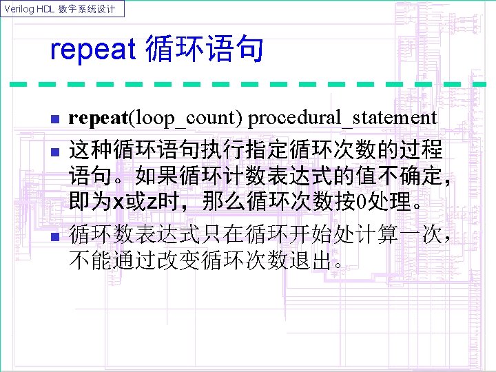
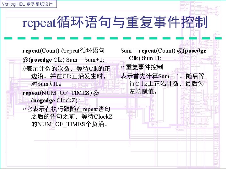
Verilog HDL 数字系统设计 参数化移位乘法器 module multiplier(result, op_a, op_b); parameter size = 8; input [size: 1] op_a, op_b; output [2*size: 1] result; reg [2*size: 1] shift_opa, result; reg [size: 1] shift_opb; always @(op_a or op_b) begin result = 0; shift_opa = op_a; // Zero extend left shift_opb = op_b; repeat (size) begin #10 if (shift_opb[1]) result = result + shift_opa; shift_opa = shift_opa << 1; // Shift left shift_opb = shift_opb >> 1; // Shift right end endmodule
Verilog HDL 数字系统设计 initial begin count = 0; while (count < 101) begin $display (“Count = %d”, count); count = count + 1; end reg [15: 0] Word; while (Word) begin if (Word[0]) Count. Ones = Count. Ones + 1; Word = Word >> 1; end
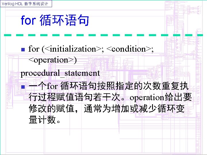
Verilog HDL 数字系统设计 // 寻找x for (index = 0; index < size; index = index + 1) if (val[index] === 1'bx) $display ("found an X"); // 存储器赋值 for (i = size; i != 0; i = i - 1) memory[i-1] = 0; // 阶乘 factorial = 1; for (j = num; j != 0; j = j - 1) factorial = factorial * j;
Verilog HDL 数字系统设计 integer i; // declare the index for the FOR LOOP always @(inp or cnt) begin result[7: 4] = 0; result[3: 0] = inp; if (cnt == 1) begin for (i = 4; i <= 7; i = i + 1) begin result[i] = result[i-4]; end result[3: 0] = 0; end
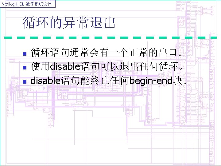
Verilog HDL 数字系统设计 begin: break for (I = 0; I < n; I = I + 1) begin: continue if (a == 0) disable continue; … if (a == b) disable break end
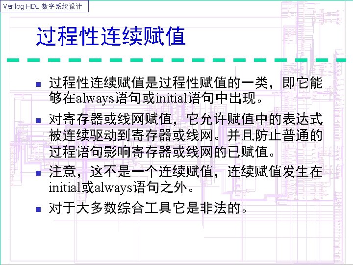
Verilog HDL 数字系统设计 module latch_quasi (q, en, d); input en, d; output q; reg q; always @(en) if (en) assign q = d; else deassign q; endmodule
Verilog HDL 数字系统设计 assign 和 deassign 覆盖寄存器上的当前值。 reg state_reg ; initial begin #10 assign state_reg = 2 ; #20 deassign state_reg ; end n
Verilog HDL 数字系统设计 reg(wire) scan_reg. q ; initial begin #10 force scan_reg. q = 0 ; #20 release scan_reg. q ; end
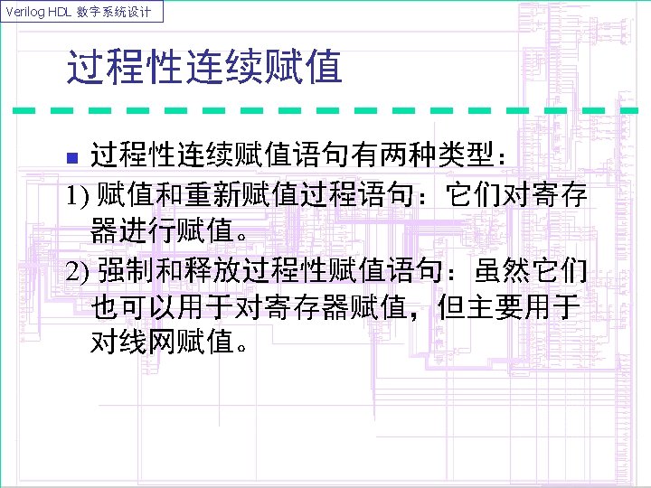
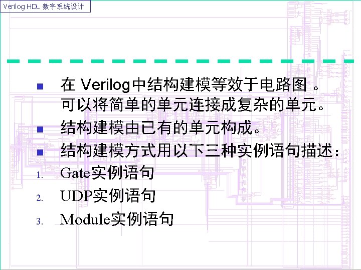
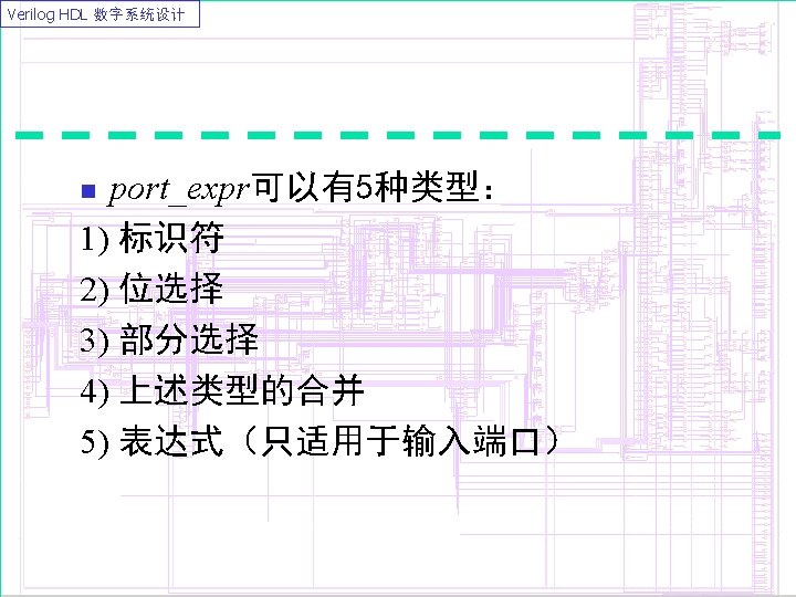
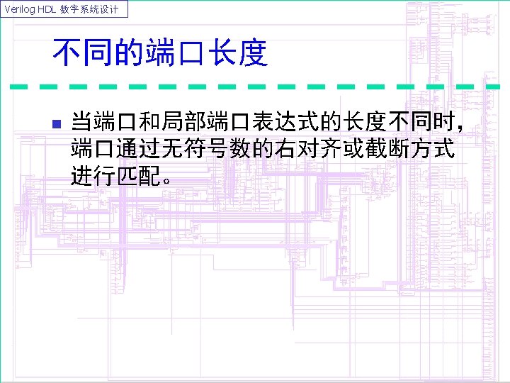
Verilog HDL 数字系统设计 reg[2: 0] Colt; . . . Colt = 2; force Colt = 1; . . . release Colt; // Colt 保持值为 1。. . . assign Colt = 5; . . . force Colt = 3; . . . release Colt; // Colt值变为 5。. . .
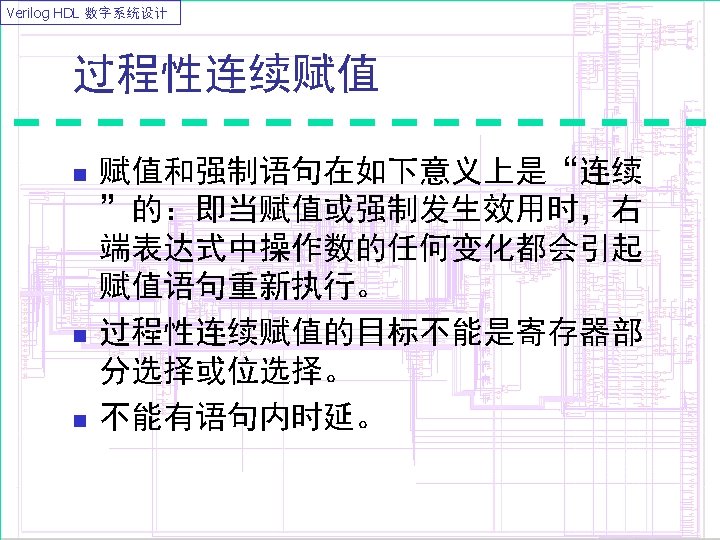
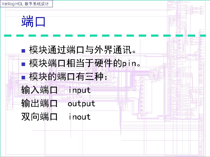
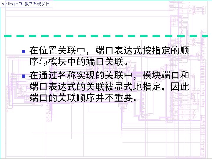
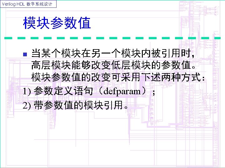
Verilog HDL 数字系统设计 module Interacting (Serial_In, Clk, Parallel_Out); input Serial_In, Clk; output [0: 7] Parallel_Out; reg Ready, Ack; wire [0: 7] data; `include "Read_Word. v" // Read_Word任务在此文件中定义。
Verilog HDL 数字系统设计 always begin: RX Read_Word(Serial_In, Clk, Data) ; / *任务Read_Word在每个时钟周期 读取串行数据,将其转换为并行 数据并存于Data中。*/ Ready = 1; wait(Ack) ; Ready = 0; # 40 ; end always begin: MP # 25 ; Parallel_Out = Data; Ack = 1; #25 Ack = 0; wait (ready) ; endmodule
Verilog HDL 数字系统设计 同步vs. 异步 module sync (d, clk, clr, pre, q); input d, clk, clr, pre ; output q ; reg q ; always @(posedge clk) begin if (clr) q <= 1’b 0 ; else if (pre) q <= 1’b 1 ; else q <= d ; endmodule async (d, clk, clr, q); input d, clk, clr ; output q ; reg q ; always @(posedge clk or posedge clr) begin if (clr) q <= 1’b 0 ; else q <= d ; endmodule
Verilog HDL 数字系统设计 模块 Verilog HDL中,基本单元定义成模块形式,如下所示: module Module_name (Port_list) Port declarations (if ports are present) //端口队列port_list列出了该模块通过哪些端口与外部模块通信。 Parameters (optional) Data type declarations Continuous Assignments (assign) Procedural Blocks (initial and always) behavioral statements Instantiation of lower-level modules Tasks and Functions Timing Specifications endmodule n
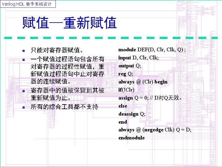
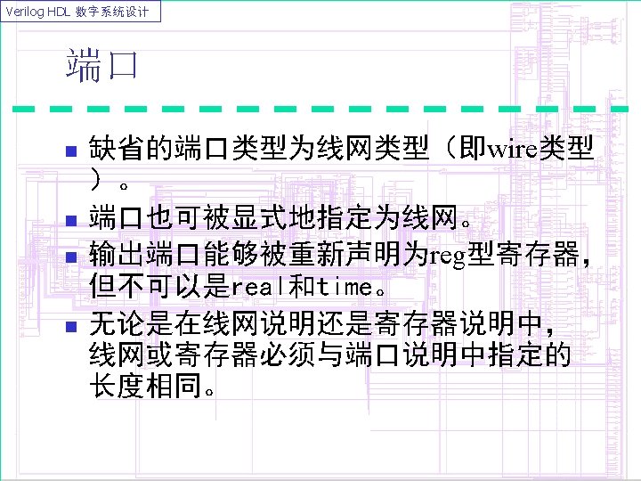
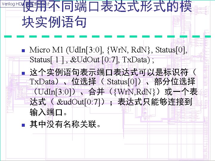
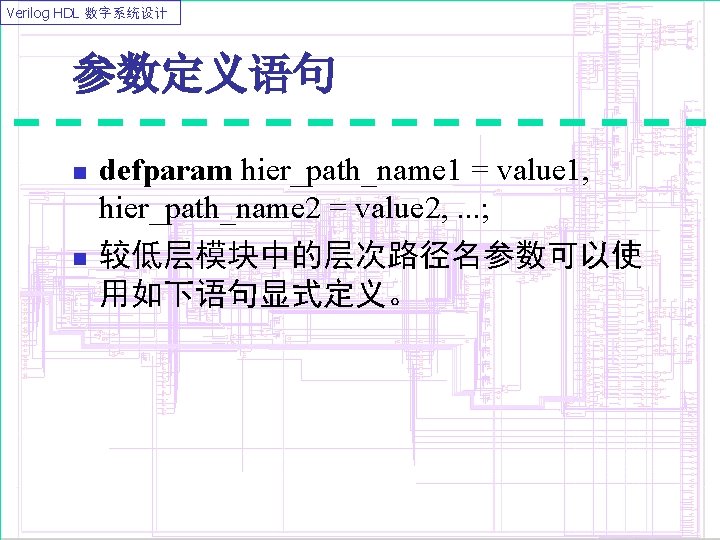
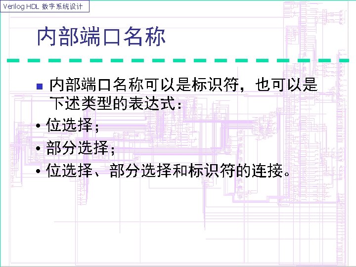
Verilog HDL 数字系统设计 端口说明 module Micro (PC, Instr, Next. Addr ); input [3: 1] PC; output [1: 8] Instr; inout [16: 1] Next. Addr; wire [16: 1] Next. Addr; //该说明是可选的,但如果指定了,就必须与 它的端口说明保持相同长度。显示说明。 reg [1: 8] Instr; / /Instr被说明为reg类型,因此它能在always 语句或在initial语句中赋值。. . . endmodule
Verilog HDL 数字系统设计 两个半加器模块构造全加器 module HA(A , B , S , C); input A , B; output S, C; assign #2 S= A ^ B; assign #1 C= A & B; endmodule FA(P, Q, Cin, Sum, Cout ) ; input P, Q, Cin; output Sum, Cout; parameter OR_DELAY = 1; wire S 1, C 2; HA h 1 (P, Q, S 1, C 1); //通过位置关联。 HA h 2 (. A(C i n), . S(S u m), . B(S 1), . C(C 2)); //通过端口与信号的名字关联。 or #2 O 1 (Cout, C 1, C 2) ; endmodule
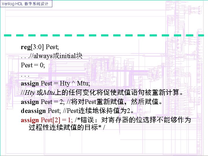
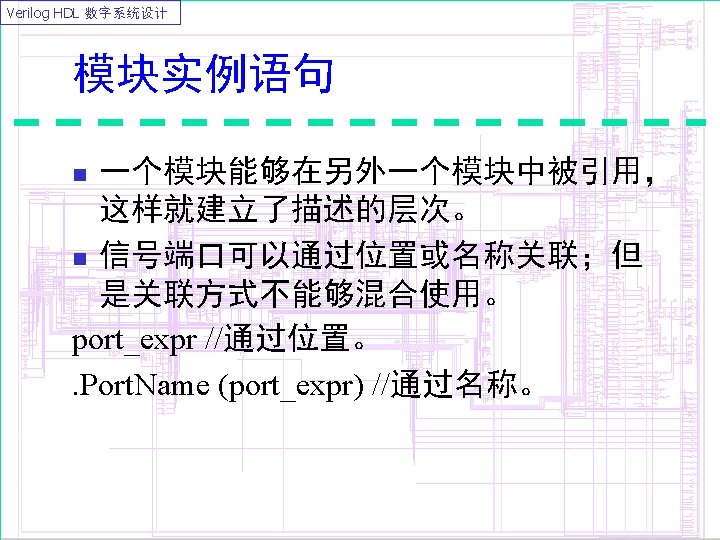
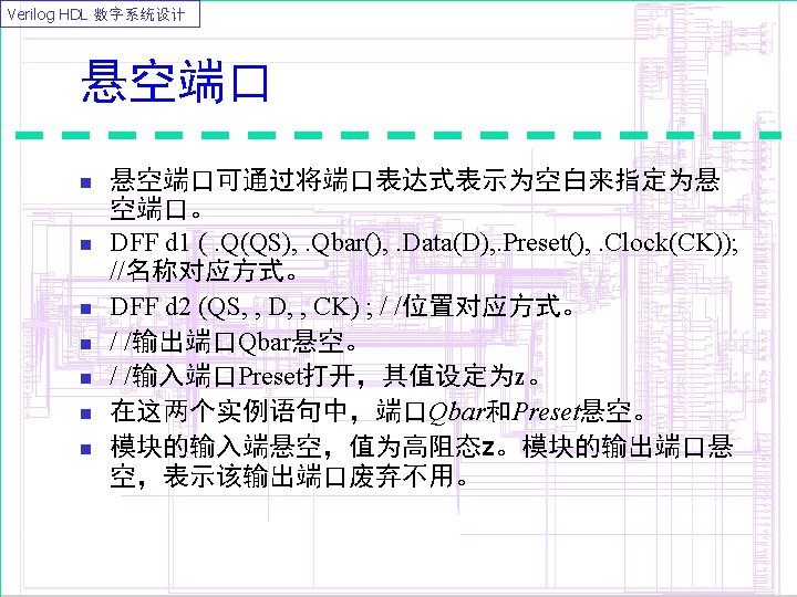
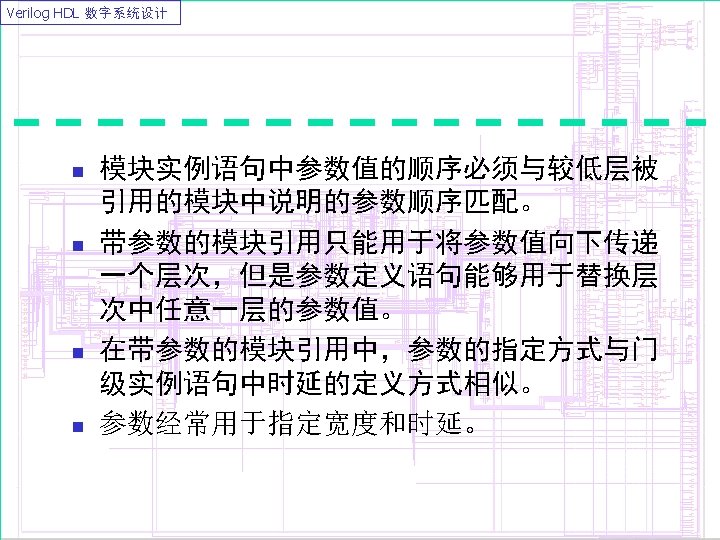
Verilog HDL 数字系统设计 module Child(Pba, Ppy) ; input [5: 0] Pba; output [2: 0] Ppy; . . . endmodule Top; wire [1: 2] Bdl; wire [2: 6] Mpr; Child C 1 (Bdl, Mpr) ; endmodule
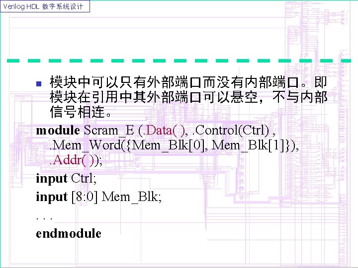
Verilog HDL 数字系统设计 改变较低层次模块的参数 module full_adder(fco, fsum, cin, a, b); output fco, fsum; input cin, a, b; wire c 1, s 1, c 2; defparam u 1. and_delay = 4, u 1. xor_delay = 6; defparam u 2. and_delay = 3, u 2. xor_delay = 5; half_adder u 1(c 1, s 1, a, b); half_adder u 2(. a(s 1), . b(cin), . sum(fsum), . co(fco)); or u 3(fco, c 1, c 2); endmodule half_adder (a, b, sum, co); parameter and_delay = 8, xor_delay = 8; …. endmodule
Verilog HDL 数字系统设计 带参数值的模块引用 module full_adder(fco, fsum, cin, a, b); output fco, fsum; input cin, a, b; wire c 1, s 1, c 2; half_adder #(4, 6) u 1(c 1, s 1, a, b); half_adder #(3, 5) u 2(. a(s 1), . b(cin), . sum(fsum), . co(fco)); or u 3(fco, c 1, c 2); endmodule half_adder (a, b, sum, co); parameter and_delay = 8, xor_delay = 8; …. endmodule
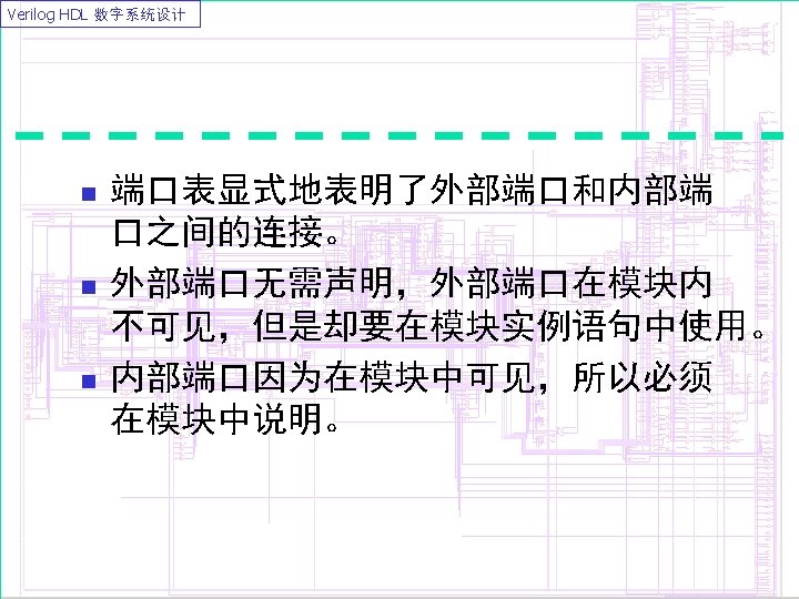
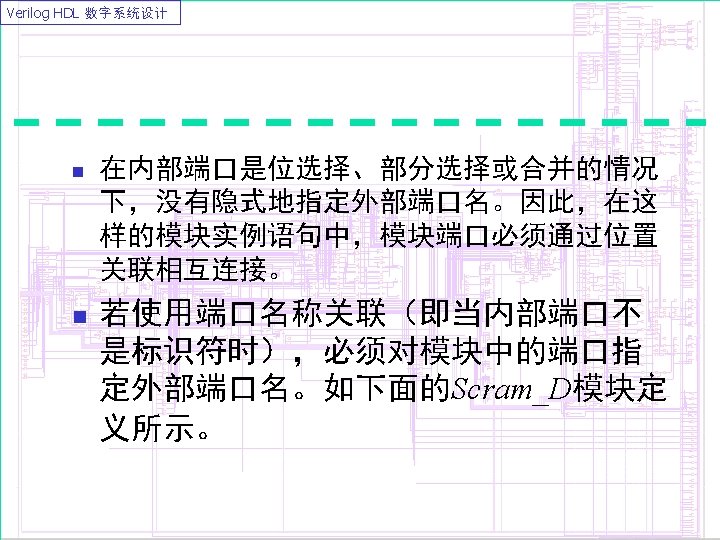
Verilog HDL 数字系统设计 外部端口 n 外部可见的模块端口 module Scram_A(Arb, Ctrl, Mem_Blk, Byte); input[0: 3] Arb; input Ctrl; input [8: 0] Mem_Blk; output [0: 3] Byte; . . . endmodule n Arb, Ctrl, Mem_Blk, Byte为模块端口。这些端口同时也是外部端口。 n 在模块Scram_A中,外部端口名称隐式地指定。
Verilog HDL 数字系统设计 n n HDL中提供显式方式指定外部端口名称。 语法形式:. external_port_name(internal_port_name)
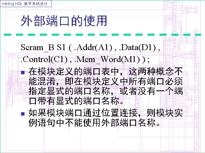
Verilog HDL 数字系统设计 module Scram_B (. Data(Arb) , . Control(Ctrl) , . Mem_Word(Mem_Blk) , . Addr(Byte)) ; input[0: 3] Arb; input Ctrl; input [8: 0] Mem_Blk; output [0: 3] Byte; . . . endmodule n n 外部端口是Data、Control、Mem_Word和Addr。 内部端口是Arb, Ctrl, Mem_Blk, Byte
Verilog HDL 数字系统设计 module Scram_C (Arb[0: 2] , Ctrl, {Mem_Blk[0] , Mem_Blk[1]} , Byte[3] ) ; input [0: 3] Arb; input Ctrl; input [8: 0] Mem_Blk; output [0: 3] Byte; . . . endmodule
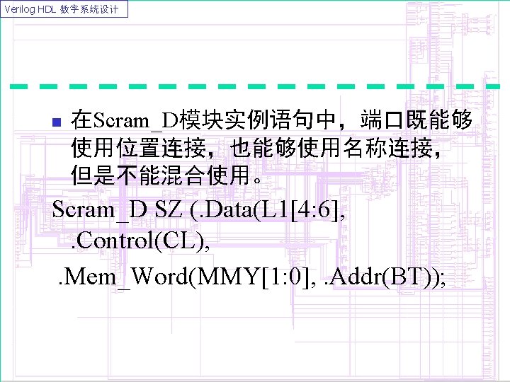
Verilog HDL 数字系统设计 module Scram_D (. Data(Arb[0: 2]), . Control(Ctrl), . Mem_Word({Mem_Blk[0], Mem_Blk[1]}), . Addr(Byte[3])); input [0: 3] Arb; input Ctrl; input [8: 0] Mem_Blk; output [0: 3] Byte; . . . endmodule
Verilog HDL 数字系统设计 Verilog HDL允许一个内部端口能与多个 外部端口连接。 module Fan. Out (. A(Ctrl. In) , . B(Cond. Out), . C(Cond. Out)) ; input. Ctrl. In; output Cond. Out; assign Cond. Out = Ctrl. In; endmodule n
Verilog HDL 数字系统设计 结构模型描述十进制计数器 module Decade_Ctr (Clock, Z) ; input Clock; output [0: 3] Z; and A 1 (S 1, Z[2], Z[1]); // 4个模块实例语句: JK_FF JK 1(. J(1'b 1), . K(1'b 1), . CK(Clock), . Q(Z[0]) , . NQ( )), JK 2(. J(S 2), . K(1'b 1), . CK(Z[0]), . Q(Z[1]) , . NQ()), JK 3(. J(1'b 1), . K(1'b 1), . CK(Z[1]), . Q(Z[2]), . NQ()), JK 4(. J(S 1), . K(1'b 1), . CK(Z[0]), . Q(Z[3]), . NQ(S 2)); endmodule
Verilog HDL 数字系统设计 3位可逆计数器的逻辑 module Up_Down(Clk, Cnt_Up, Cnt_Down, Q) ; input Clk, Cnt_Up, Cnt_Down; output [0: 2] Q; wire S 1, S 2, S 3, S 4, S 5, S 6, S 7, S 8; JK_FF JK 1(1'b 1, Clk, Q[0], S 1), JK 2(1'b 1, S 4, Q[1] , S 5), JK 3(1'b 1, S 8, Q[2], ); and A 1(S 2, Cnt_Up, Q[0]), A 2(S 3, S 1, Cnt_Down), A 3(S 7, Q[1], Cnt_Up), A 4(S 6, S 5, Cnt_Down); or O 1(S 4, S 2, S 3) , O 2(S 8, S 7, S 6); endmodule