VERILOG HDL II MOORE MACHINE REVISITED A good









- Slides: 32
VERILOG HDL – II
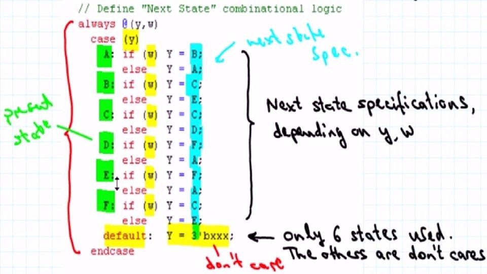
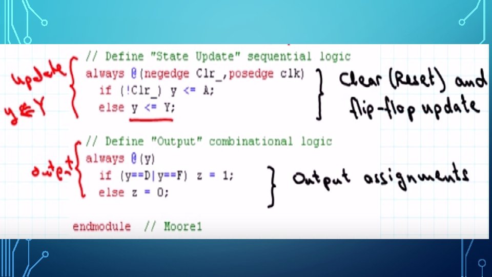
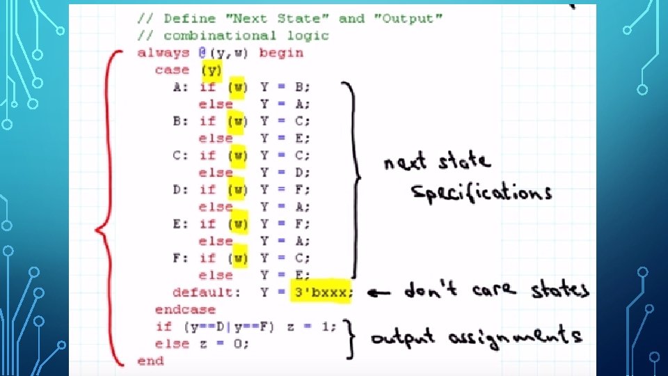
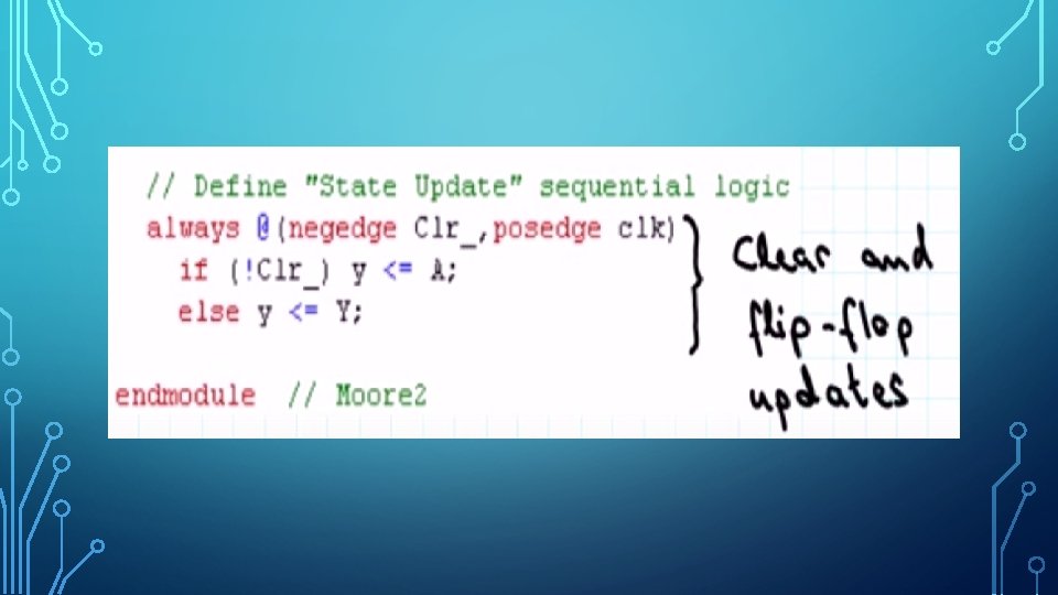
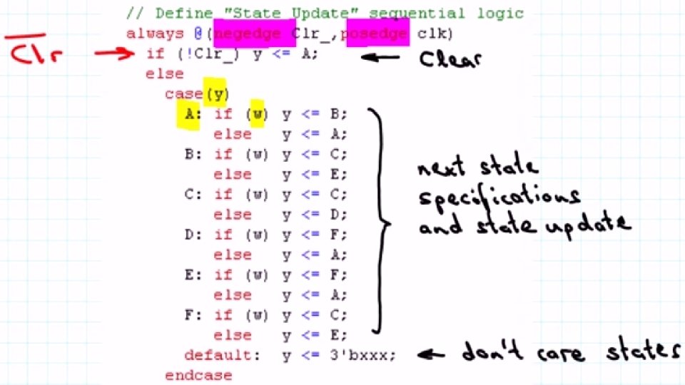
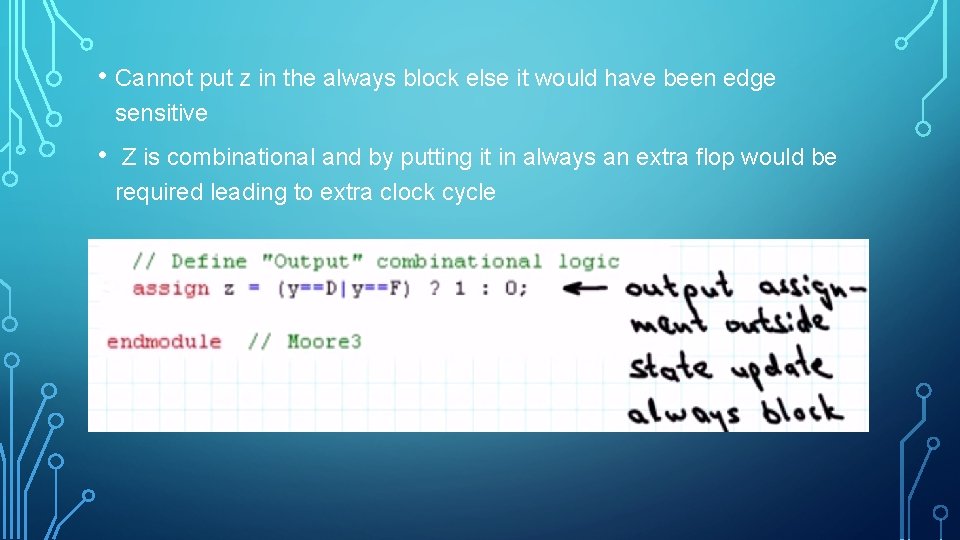
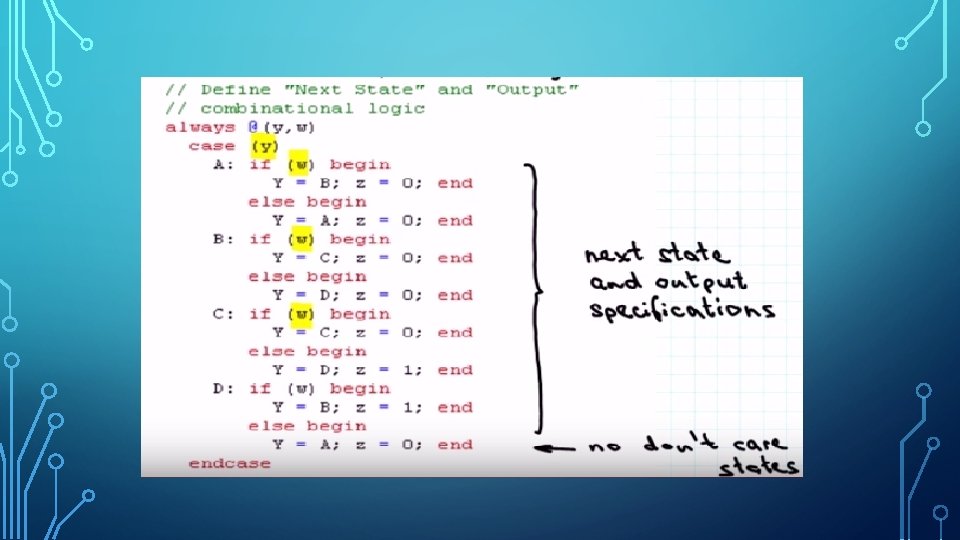
MOORE MACHINE – REVISITED A good way to specify Moore is to use separate procedural blocks for • Next State Combinational Logic • For the state update Sequential Logic • Output Combinational Logic
THE THREE STATES OF MOORE:
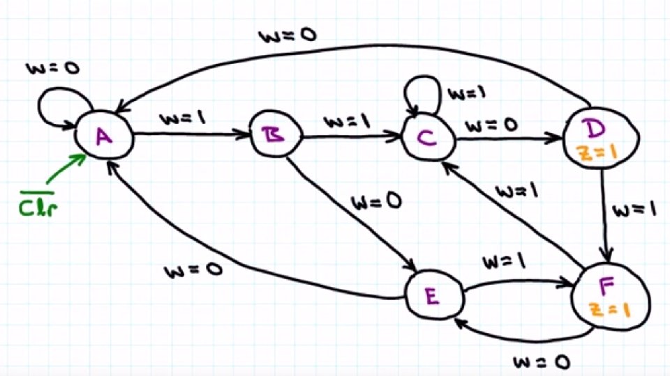
MOORE DUAL SEQUENCE OVERLAPPING: • A Moore type sequence FSM that reads a binary sequence w and sets z = 1 if either a 110 or a 101 pattern with overlaps is detected. • The state diagram for such a machine is as follows.
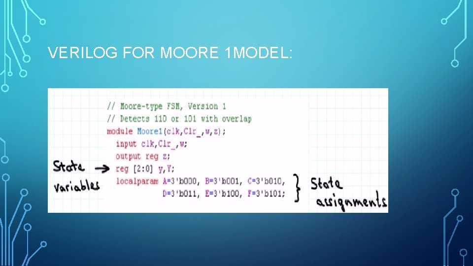
VERILOG FOR MOORE 1 MODEL:
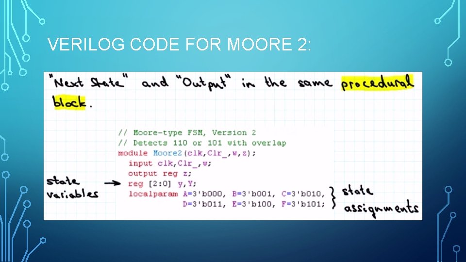
VERILOG CODE FOR MOORE 2:
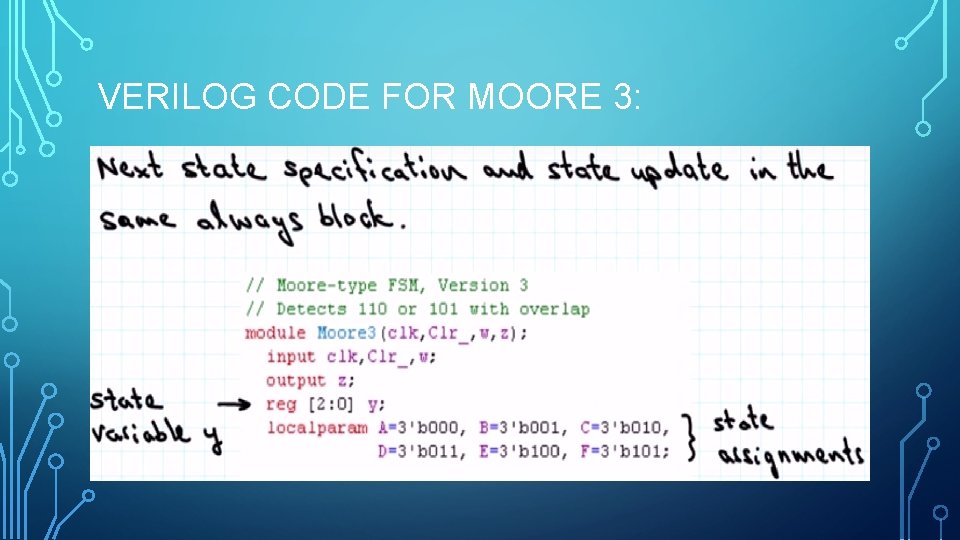
VERILOG CODE FOR MOORE 3:
• Cannot put z in the always block else it would have been edge sensitive • Z is combinational and by putting it in always an extra flop would be required leading to extra clock cycle
MEALY DESIGN OF THE SEQUENCE
I/O DECLARATION IS THE SAME AS MOORE
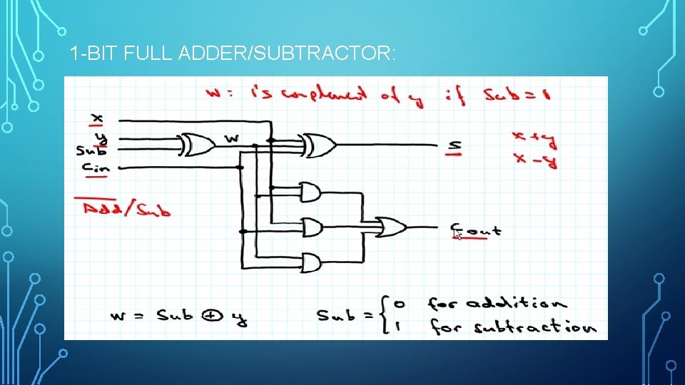
1 -BIT FULL ADDER/SUBTRACTOR:
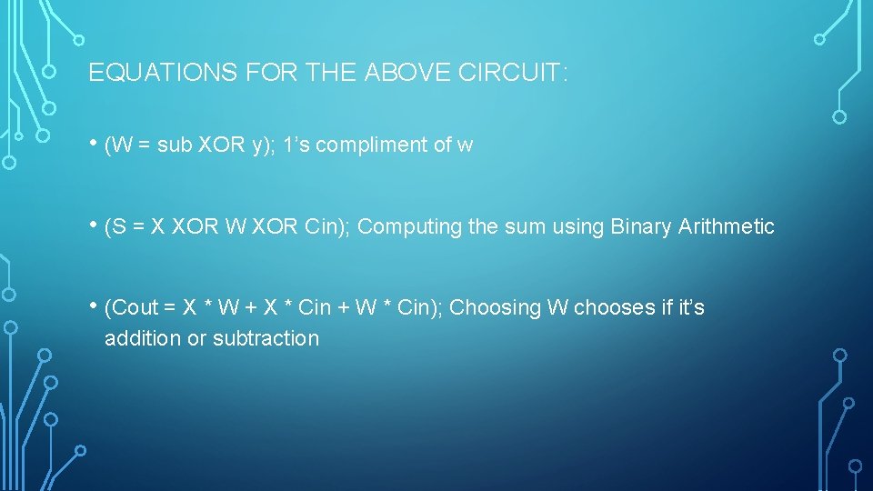
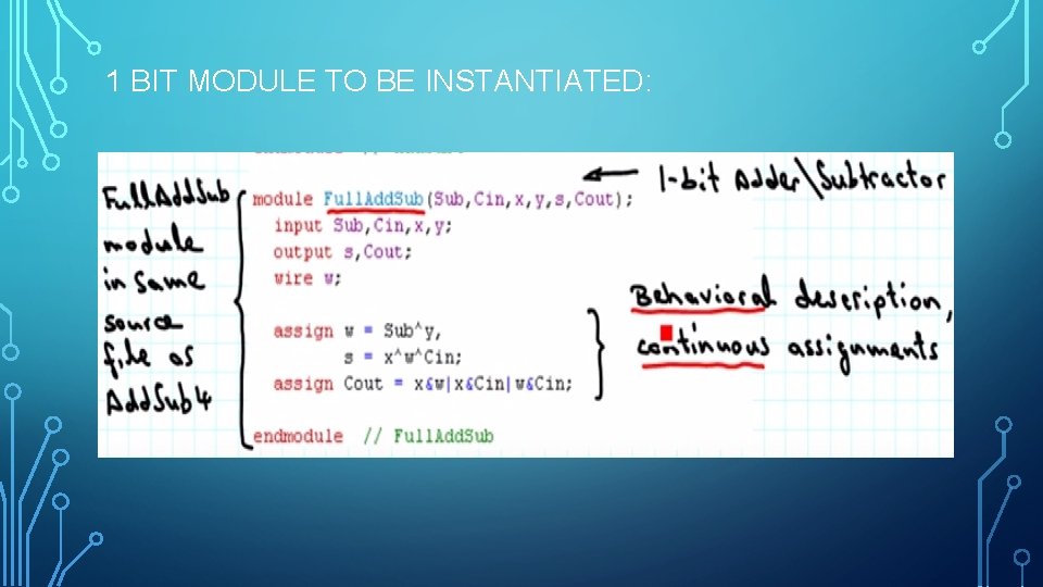
EQUATIONS FOR THE ABOVE CIRCUIT: • (W = sub XOR y); 1’s compliment of w • (S = X XOR W XOR Cin); Computing the sum using Binary Arithmetic • (Cout = X * W + X * Cin + W * Cin); Choosing W chooses if it’s addition or subtraction
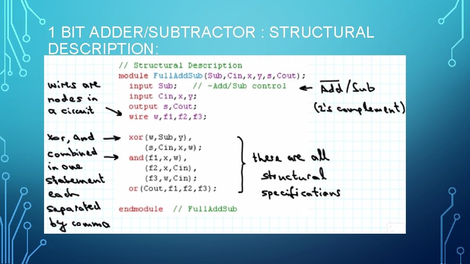
1 BIT ADDER/SUBTRACTOR : STRUCTURAL DESCRIPTION:
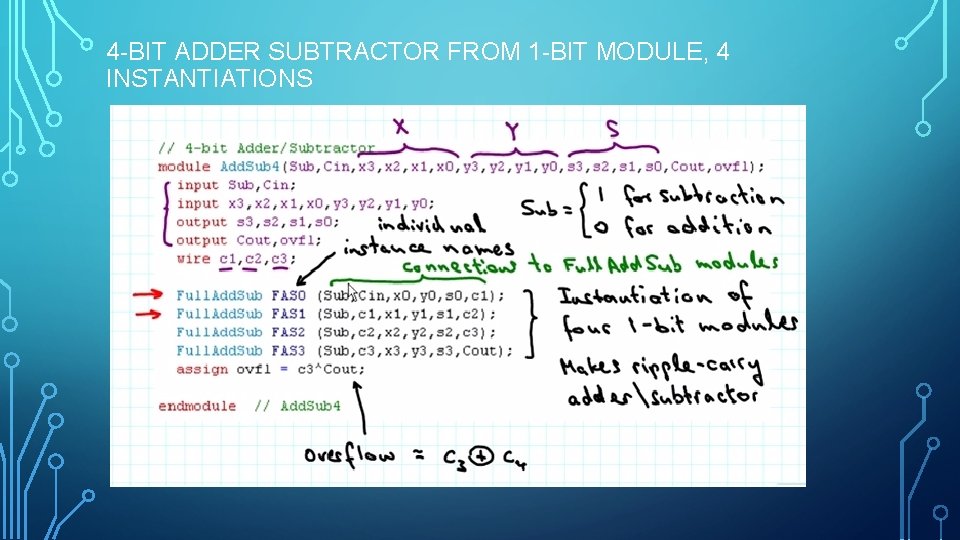
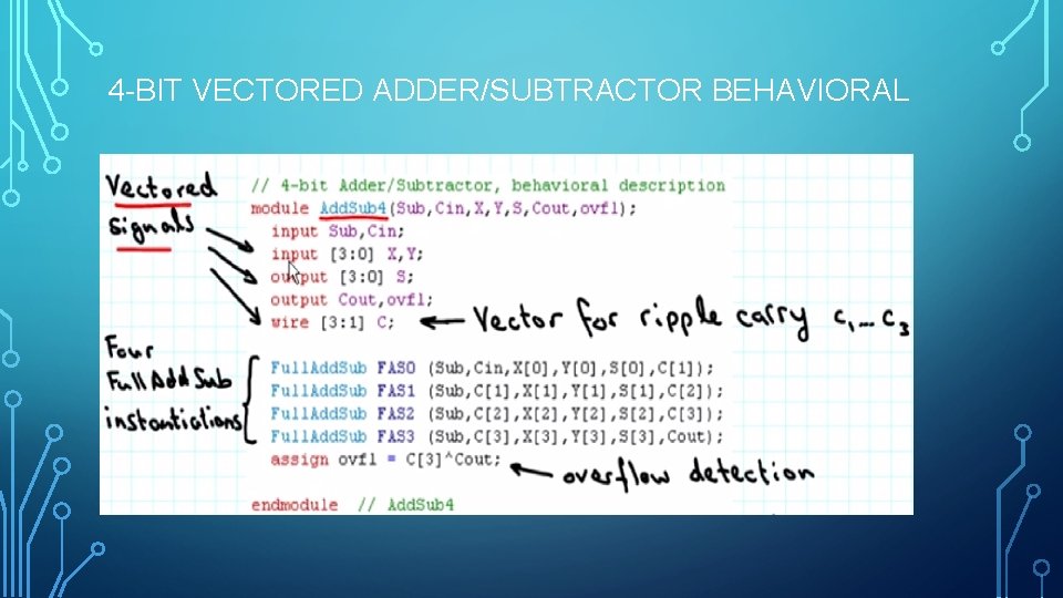
4 -BIT ADDER SUBTRACTOR FROM 1 -BIT MODULE, 4 INSTANTIATIONS
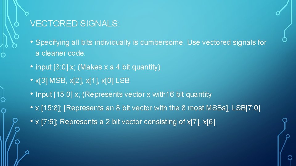
VECTORED SIGNALS: • Specifying all bits individually is cumbersome. Use vectored signals for a cleaner code. • input [3: 0] x; (Makes x a 4 bit quantity) • x[3] MSB, x[2], x[1], x[0] LSB • Input [15: 0] x; (Represents vector x with 16 bit quantity • x [15: 8]; [Represents an 8 bit vector with the 8 most MSBs], LSB[7: 0] • x [7: 6]; Represents a 2 bit vector consisting of x[7], x[6]
4 -BIT VECTORED ADDER/SUBTRACTOR BEHAVIORAL
1 BIT MODULE TO BE INSTANTIATED:
GENERALIZING THE SIZE OF A LARGE MODULE • The ripple carry adders we created have a fixed length. If a 32 -bit or a 64 - bit adder was needed, we would need as many instantiations of Full. Add. Sub. • Desirable from designers perspective to define an Add. Sub module that n number of bits can be set to any value. • In Verilog such a construct exists, can specify n as : parameter n = 15 and then write input [n-1: 0] x. This case is for 16 bit vector.
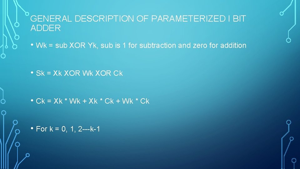
GENERAL DESCRIPTION OF PARAMETERIZED I BIT ADDER • Wk = sub XOR Yk, sub is 1 for subtraction and zero for addition • Sk = Xk XOR Wk XOR Ck • Ck = Xk * Wk + Xk * Ck + Wk * Ck • For k = 0, 1, 2 ---k-1
THE FOR LOOP: • In Verilog the repetitive structure for the of the ripple carry adder/subtractor can be specified using for procedural statement, (for k=1; k<n; k=k+1) • The syntax is same as C/C++ except that increments and decrements have to specified explicitly as k = k+1 and k = k-1, since ++, -- operators doesn’t exist in Verilog. • For is a procedural statement and needs to be put inside a procedural block such as always block. Outputs of procedural blocks goes to registers.