Transport Layer l Introduction of Transport Layer l


 b) c) Services Provided to the Upper Layers Transport Service")


 Environment of the data link layer. (b) Environment of the transport")


 l No-frills extension of “best-effort”")
![UDP: User Datagram Protocol [RFC 768] l l l “no frills, ” “bare bones”](https://slidetodoc.com/presentation_image/3e65819b00060e90ba2d546416f51e88/image-29.jpg "UDP: User Datagram Protocol [RFC 768] l l l “no frills, ” “bare bones”")


: called from above, (e. g. , by app.")


 is a critically important")


 sequence number")
 ACK: ACK #")


 TCP connection establishment in the normal case. (b)")

 TCP connection management finite state machine. The heavy solid")
 Window")


 transmission rate limited by")


 When connection begins, increase rate exponentially until first loss event:")

 OPEN loop and")


- Slides: 86
Transport Layer l Introduction of Transport Layer l The Transport Layer Services l Elements of transport protocol l UDP l Principal of Reliable Data transfer l TCP Congestion Control l Quality of Service l Performance
Introduction of Transport layer l l The transport layer is the core of the Internet model. The application layer programs interact with each other using the services of the transport layer. Lists the functiom of a transport layer. Transport layer packetizing Connection Control Addressing Providing reliability
Transport layer functions : l This layer breaks message into packets. l It performance error recovery if the lower layer are not adequately error free. l Function of flow control if not done l Function of multiplexing and demultiplexing sessions together.
OBJECTIVES: To define process-to-process communication at the transport layer and q compare it with host-to-host communication at the network layer. q To discuss the addressing mechanism at the transport layer, to discuss port numbers, and to define the range of port numbers used for different purposes. q To explain the packetizing issue at the transport layer: encapsulation and decapsulation of messages. q To discuss multiplexing (many-to-one) and demultiplexing (one-to-many) services provided by the transport layer.
The Transport Service a) b) c) Services Provided to the Upper Layers Transport Service Primitives Berkeley Sockets
Services Provided to the Upper Layers The network, transport, and application layers.
Why the transport layer ? 1. The network layer exists on end hosts and routers in the network. The end-user cannot control what is in the network. So the end-user establishes another layer, only at end hosts, to provide a transport service that is more reliable than the underlying network service. 2. While the network layer deals with only a few transport entities, the transport layer allows several concurrent applications to use the transport service. 3. It provides a common interface to application writers, regardless of the underlying network layer. In essence, an application writer can write code once using the transport layer primitive and use it on different networks (but with the same transport layer).
Transport Service Primitives The primitives for a simple transport service.
Transport Service Primitives The nesting of TPDUs, packets, and frames.
Berkeley Sockets The socket primitives for TCP.
Transport Protocol (a) Environment of the data link layer. (b) Environment of the transport layer. Both data link layer and transport layer do error control, flow control, sequencing. The differences are: 1. Storage capacity in subnet. Frames must arrive sequentially, TPDUs can arrive in any sequence. 2. Frames are delivered to hosts, TPDUs need to be delivered to users, so per user addressing and flow control within the hosts is necessary.
Transport Layer l Introduction of Transport Layer l The Transport Layer Services l Elements of transport protocol l UDP l Principal of Reliable Data transfer l TCP Congestion Control l Quality of Service l Performance
Elements of Transport Protocol ü Addressing ü Connection Establishment ü Multiplexing and Demultiplexing ü Flow Control and Buffering ü Crash Recovery
l TSAP = transport service access point l l Internet: IP address + local port ATM: AAL-SAPs Each station having only one transport entity, so a transport entity identification is not needed. The Address should include a designation of the type of transport protocol e. g. TCP, UDP.
Connection Establishment How a user process in host 1 establishes a connection with a time-of-day server in host 2.
The Connection establishment serves three main purpose l l l It allows each end to assure that the other exists. It allows negotiation of optional parameter like maximum segment size. It triggers allocation of transport entity resources like buffer space.
Establishing a connection l Tomlinson – three-way-handshake
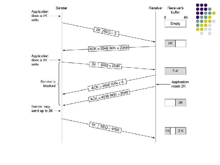
Flow Control and Buffering l l l Flow control is implemented using modified form of sliding window protocol. The window size is variable and is controlled by the receiver. The receiver sends a credit allocation to the sender. If the receiver cannot guarantee that every incoming TPDU wil be accepted, the sender will have to buffer anyway.
Flow control and buffering l Buffer organization
Multiplexing and Demultiplexing Multiplexing : many-to-one services provided by the transport layer “The Dividing flows of Data from the application into one or many packets” l Demultiplexing : one-to-many services provided by the transport layer “ Allocating each communication flow a unique identifier” l
Multiplexing l l Upward: reduce number of network connections to reduce cost Downward: increase bandwidth to avoid per connection limits
l l If the host server & router are subject to crashes, the recovery from these crashes makes some problem. When the server crash while receiving data from client, the outstanding TPDU is lost. TO recover the data, when the server comes back up, its tables are reinitialized, so it no longer knows precisely where it was. The server send a broadcast TPDU to all the other host, Just crashed and requesting that its clients inform it for the status of all open connections. Client can be in one of two states: TPDU outstanding or no TPDU outstanding Recovery from a layer N crash can only be done by layer N+1 and only if the higher layer retains enough status information.
Transport Layer l Introduction of Transport Layer l The Transport Layer Services l Elements of transport protocol l UDP l Principal of Reliable Data transfer l TCP Congestion Control l Quality of Service l Performance
l l UDP is simple, datagram-oriented, transport layer protocol. This protocol is used in place of TCP UDP is connectionless protocol provides no reliability or flow control mechanisms. It also has no error recovery procedures.
Internet Transport Protocols l l Datagram messaging service (UDP) l No-frills extension of “best-effort” IP Reliable, in-order delivery (TCP) l Connection set-up Discarding of corrupted packets l Retransmission of lost packets l Flow control l Congestion control (next lecture) Other services not available l Delay guarantees l Bandwidth guarantees l l
UDP: User Datagram Protocol [RFC 768] l l l “no frills, ” “bare bones” Internet transport protocol “best effort” service, UDP segments may be: l lost l delivered out of order to app connectionless: l no handshaking between UDP sender, receiver l each UDP segment handled independently of others Why is there a UDP? l l no connection establishment (which can add delay) simple: no connection state at sender, receiver small segment header no congestion control: UDP can blast away as fast as desired
Introduction to UDP The UDP header.
Remote Procedure Call Steps in making a remote procedure call. The stubs are shaded.
Internet Checksum Example l Note l When adding numbers, a carryout from the most significant bit needs to be added to the result l Example: add two 16 -bit integers 1 1 0 0 1 1 1 0 1 0 1 wraparound 1 1 0 1 1 sum 1 1 0 1 1 0 0 checksum 1 0 0 0 0 1 1
Transport Layer l Introduction of Transport Layer l The Transport Layer Services l Elements of transport protocol l UDP l Principal of Reliable Data transfer l TCP Congestion Control l Quality of Service l Performance
l l Reliable data transfer means, data received without loss or corrupt. All the packets are delivered in the order in which they were sent. The Complexity of the reliable data transfer protocol determined by characteristics of unreliable channel.
Principles of Reliable data transfer l l l important in app. , transport, link layers top-10 list of important networking topics! characteristics of unreliable channel will determine complexity of reliable data transfer protocol (rdt)
Principles of Reliable data transfer l important in app. , transport, link layers important networking topics! l characteristics of unreliable channel will determine complexity of reliable data transfer protocol (rdt)
Principles of Reliable data transfer l l l important in app. , transport, link layers important networking topics! characteristics of unreliable channel will determine complexity of reliable data transfer protocol (rdt) Transport Layer
Reliable data transfer: getting started rdt_send(): called from above, (e. g. , by app. ). Passed data to deliver to receiver upper layer send side udt_send(): called by rdt, to transfer packet over unreliable channel to receiver deliver_data(): called by rdt to deliver data to upper receive side rdt_rcv(): called when packet arrives on rcv-side of channel
Reliable data transfer: getting started We’ll: l l l incrementally develop sender, receiver sides of reliable data transfer protocol (rdt) consider only unidirectional data transfer l but control info will flow on both directions! use finite state machines (FSM) to specify sender, receiver event causing state transition actions taken on state transition state: when in this “state” next state uniquely determined by next event state 1 event actions state 2
Transport Layer l Introduction of Transport Layer l The Transport Layer Services l Elements of transport protocol l UDP l Principal of Reliable Data transfer l TCP Congestion Control l Quality of Service l Performance
The Internet Transport Protocols: TCP 1. 2. 3. 4. 5. 6. 7. 8. 9. Introduction of TCP Features of TCP The TCP Service Model The TCP Protocol The TCP Segment Header TCP Connection Establishment TCP Connection Release TCP Connection Management Modeling TCP Transmission Policy
Introduction of TCP l l The Transmission Control Protocol (TCP) is a critically important part of the TCP/IP suite. The Transmission Control Protocol (TCP) is the connection oriented protocol whereas User Data Protocol (UDP) is connectionless protocol. Both are internet protocols used in the transport layer. The TCP provides reliable Transmission of data in IP environment. TCP offers reliability by providing connectionoriented , end-to-end reliable packet delivery through an internetwork.
Features of TCP l l l TCP is a process-to-process protocal. TCP uses port numbers. It is connection oriented protocol. It uses flow and error control mechanisms. TCP is a reliable protocol.
TCP: Models 2581 l l RFCs: 793, 1122, 1323, 2018, (The 800 lbs gorilla in the transport stack! PAY ATTENTION!!) point-to-point: l one sender, one receiver (not multicast) reliable, in-order byte steam: l no “message boundaries” l In App layer, we need delimiters. pipelined: l TCP congestion and flow control set window size send & receive buffers l l full duplex data: bi-directional data flow in same connection l MSS: maximum segment size connection-oriented: l handshaking (exchange of control msgs) init’s sender, receiver state (e. g. , buffer size) before data exchange flow controlled: l sender will not overwhelm receiver
TCP protocol l Three-way handshake to set up connections Every byte has its own 32 -bit sequence number l Wrap around l 32 -bit Acks; window size in bytes Segment = unit of data exchange l 20 -byte header + options + data l Limits for size l l Data from consecutive writes may be accumulated in a single segment l Fragmentation possible Sliding window protocol l l 64 Kbyte MTU, agreed upon for each direction
TCP header l l l l source & destination ports (16 bit) sequence number (32 bit) Acknowledgement number (32 bit) Header length (4 bits) in 32 -bit words 6 flags (1 bit) window size (16 bit): number of bytes the sender is allowed to send starting at byte acknowledged checksum (16 bit) urgent pointer (16 bit) : byte position of urgent data
TCP segment structure 32 bits URG: urgent data (generally not used) ACK: ACK # valid PSH: push data now (generally not used) RST, SYN, FIN: connection estab (setup, teardown commands) Internet checksum (as in UDP) source port # dest port # sequence number acknowledgement number head not UA P R S F len used checksum Receive window Urg data pnter Options (variable length) application data (variable length) counting by “bytes” of data (not segments!) # bytes rcvr willing to accept Due to this field we have a variable length header
Establishing a connection l l Problem: delayed duplicates! Scenario: l Correct bank transaction l l connect data transfer disconnect Problem: same packets are received in same order a second time! Recognized?
Establishing a connection l Connection establishment in a TCP session is initialized through a three-way handshake. To establish the connection, one side pasively waits for an incoming connection by executing the LISTEN and ACCEPT primitives, either specifying a specific source. l connection identifier l Never reused! l Maintain state in hosts Satisfactory solutions
TCP Connection Establishment 6 -31 (a) TCP connection establishment in the normal case. (b) Call collision.
TCP Connection Management Modeling The states used in the TCP connection management finite state machine.
TCP Connection Management Modeling (2) TCP connection management finite state machine. The heavy solid line is the normal path for a client. The heavy dashed line is the normal path for a server. The light lines are unusual events. Each transition is labeled by the event causing it and the action resulting from it, separated by a slash.
TCP transmission policy l l Window size decoupled from Acks (ex. next slides) Window = 0 no packets except for l Urgent data 1 byte segment to send Ack & window size Incoming user data may be buffered l May improve performance: less segments to send Ways to improve performance: l Delay acks and window updates for 500 msec l Nagle’s algorithm l Silly window syndrome l l l
Transport Layer l Introduction of Transport Layer l The Transport Layer Services l Elements of transport protocol l UDP l Principal of Reliable Data transfer l TCP Congestion Control l Quality of Service l Performance
Principles of Congestion Control Congestion: l l informally: “too many sources sending too much data too fast for network to handle” different from flow control! = l l end-to-end issue! manifestations: l lost packets (buffer overflow at routers) l long delays (queue-ing in router buffers) a top-10 problem!
Approaches towards congestion control Two broad approaches towards congestion control: Network-assisted congestion end-to-end congestion control: l routers provide feedback to l no explicit feedback end systems l single bit indicating from network congestion (SNA, ATM) l congestion inferred l explicit rate sender should from end-system send at observed loss, delay l approach taken by TCP
TCP Congestion Control l l How to detect congestion? : Rare for wired networks Packet loss Timeout caused by packet loss: reasons l l Transmission errors Packed discarded at congested router Hydraulic example illustrating two limitations for sender!
TCP congestion control
TCP Congestion Control l l How to detect congestion? : Rare Timeout caused by packet loss: reasons l l Transmission errors loss router congestion Packed discarded at. Packet congested Approach: 2 windows for sender Minimum of Receiver window Congestion window
TCP Congestion Control l l end-end control (no network assistance) transmission rate limited by congestion window size, Congwin, over segments: Congwin l w segments, each with MSS bytes sent in one RTT: w * MSS throughput = RTT Bytes/sec
TCP timer management l How long should the timeout interval be? l Data link: expected delay predictable l Transport: different environment; impact of l Host Network (routers, lines) unpredictable l l Consequences l Too small: unnecessary retransmissions Too large: poor performance Solution: adjust timeout interval based on continuous measurements of network performance l l
TCP timer management Data link layer Transport layer
Transport Layer l Introduction of Transport Layer l The Transport Layer Services l Elements of transport protocol l UDP l Principal of Reliable Data transfer l TCP Congestion Control l Quality of Service l Performance
Congestion Control 1. 2. 3. 4. 5. 6. Congestion Control Additive Increase, Multiplicative Decrease Control(AIMD) Slow start Method Causes of Congestion General Principles of Congestion Control Congestion Prevention Policies
1. Congestion Control l TCP uses a form of end to end flow control. Both are sender and the receiver agree on a common window size for packet flow. The window size represents the number of bytes that the source can send at a time. l TCP has three congestion control methods Additive increase Slow start Retransmit 1. 2. 3.
2. TCP congestion control: additive increase, multiplicative decrease r Approach: increase transmission rate (window size), Saw tooth behavior: probing for bandwidth congestion window size probing for usable bandwidth, until loss occurs m additive increase: increase Cong. Win by 1 MSS every RTT until loss detected m multiplicative decrease: cut Cong. Win in half after loss time
TCP Congestion Control: details l sender limits transmission: Last. Byte. Sent-Last. Byte. Acked Cong. Win l Roughly, rate = l Cong. Win Bytes/sec RTT Cong. Win is dynamic, function of perceived network congestion How does sender perceive congestion? l loss event = timeout or 3 duplicate acks l TCP sender reduces rate (Cong. Win) after loss event three mechanisms: l AIMD l slow start l conservative after timeout events
3. Slow Start Method l l 1. 2. Slow start method increase the congestion window size nonlinearly and in most cases exponentially, as compared to the linear increase in additive increase. The slow start method is normally used Just after a TCP connection is set up. When a source is blocked, waiting for a timeout.
TCP Slow Start (more) When connection begins, increase rate exponentially until first loss event: l l l double Cong. Win every RTT done by incrementing Cong. Win for every ACK received Summary: initial rate is slow but ramps up exponentially fast Host A RTT l Host B one segme nt two segme nts four segme nts time
4. Causes of Congestion l l When too many packets rushing to a node or part of network , the network performance degrades, and this situation is called as Congestion Control is a procces of maintaining the number of packets in a network below a certain level at which performance falls off. Congestion Control makes sure that subnet is able to carry the offered traffic.
5. General Principal of Congestion Control l Two Group : (1) OPEN loop and (2) CLOSED loop Open loop solutions attempt to solve the problem by good design, to make sure it does not occur in the first place. Closed loop solutions are based on the concept of a feedback loop. One part is a Pass this informance to places where action can be taken.
6. Congestion Prevention Policies l Data link layer l Network layer 1. Flow control policy ACK policy Retransmission policy Out of order caching policy 1. Routing algorithm Packet queueing service policy Packet Lifetime management policy Packet discard policy 2. 3. 4. 2. 3. 4.
l 1. 2. 3. 4. 5. Transport layer policies Flow control policy Acknowledgment policy Retransmission policy Out of order caching policy Timeout determination.
Transport Layer l Introduction of Transport Layer l The Transport Layer Services l Elements of transport protocol l UDP l Principal of Reliable Data transfer l TCP Congestion Control l Quality of Service l Performance
1. Quality of Service l l l In any multimedia application audio/video packets are delay sensitive but by internet all packets are treated equally Analyzing varying network scenarios principal of Quality of Services (Qos) needed for multimedia applications are derived. Principal 1: Packet marking allows a router to distinguish among packets belonging to different classes of traffic.
l Pricipal 2 : A degree of isolation is desirable among traffic flows, so that one flow is not adversely by another misbehaving flow. l Principal 3 : A call admission process is needed where flows declare their Qo. S requirement.
2. Policing 3. Integrated Services l Framework to provide guaranteed Qo. S to individual application sessions. l Call step process 1. Traffic specification of desired Qo. S 2. Signalling for call setup 3. Pre element call admission.
Transport Layer l Introduction of Transport Layer l The Transport Layer Services l Elements of transport protocol l UDP l Principal of Reliable Data transfer l TCP Congestion Control l Quality of Service l Performance
Performance 1. 2. 3. 4. 5. Bandwidth Throughput Letency Bandwidth- Delay Product Jitter
l l l Bandwidth : Characteristic of network. Measured : Hertz and Bits per Second Throughput “ An Actual measurement of how fast data can be transmitted where as bandwidth is a potential measurement of link” Letency “ It is time required for amessage to completely arrive at the destination from source” Components : propagation time, transmission time, quequing time and processing delay.
l Bandwidth – Delay Product The bandwidth-delay product defines the number of bits that can fill the link l Jitter It is a parameter related to delay. Jitter is introduced since different packets of data encounter different delay.