
Resident Physics Lectures Year 1 Christensen Chapter 5





- Slides: 29
Resident Physics Lectures (Year 1) Christensen, Chapter 5 Attenuation George David Associate Professor Medical College of Georgia Department of Radiology
Diagnostic X-Ray Beam Characteristics Characteristic Radiation Discrete energies Characteristic of target material Bremsstrahlung Energy range 0 – k. Vp selected
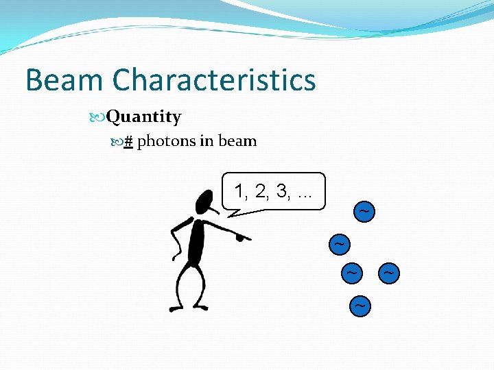
Beam Characteristics Quantity # photons in beam 1, 2, 3, . . . ~ ~ ~
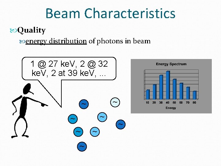
Beam Characteristics Quality energy distribution of photons in beam 1 @ 27 ke. V, 2 @ 32 ke. V, 2 at 39 ke. V, . . . ~ ~ ~ ~
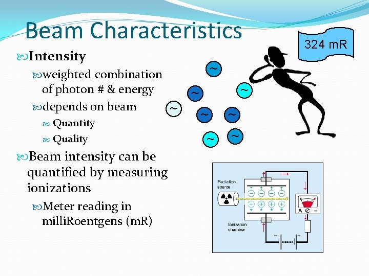
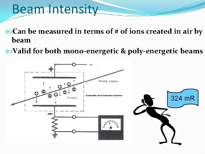
Beam Characteristics Intensity weighted combination of photon # & energy depends on beam ~ Quantity Quality Beam intensity can be quantified by measuring ionizations Meter reading in milli. Roentgens (m. R) ~ ~ ~ ~ 324 m. R
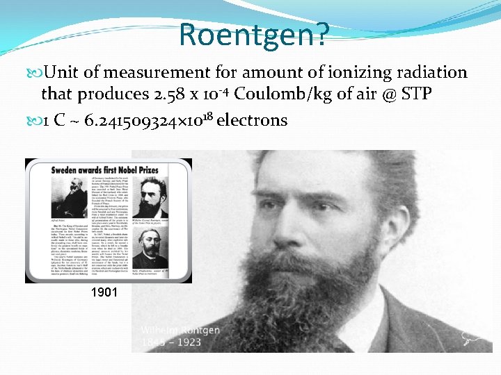
Roentgen? Unit of measurement for amount of ionizing radiation that produces 2. 58 x 10 -4 Coulomb/kg of air @ STP 1 C ~ 6. 241509324× 1018 electrons 1901
Beam Intensity Can be measured in terms of # of ions created in air by beam Valid for both mono-energetic & poly-energetic beams 324 m. R
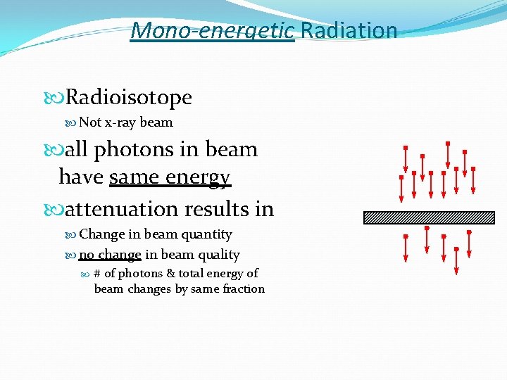
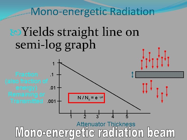
Mono-energetic Radiation Radioisotope Not x-ray beam all photons in beam have same energy attenuation results in Change in beam quantity no change in beam quality # of photons & total energy of beam changes by same fraction
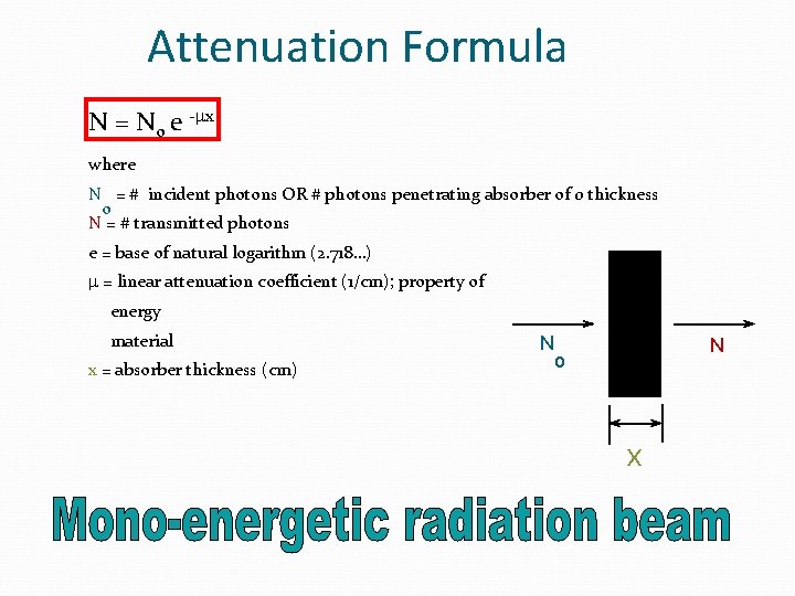
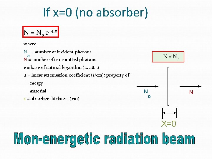
Attenuation Formula N = No e -mx where N = # incident photons OR # photons penetrating absorber of 0 thickness o N = # transmitted photons e = base of natural logarithm (2. 718…) m = linear attenuation coefficient (1/cm); property of energy material x = absorber thickness (cm) N N o x
If x=0 (no absorber) N = No e -mx where N = number of incident photons o N = number of transmitted photons e = base of natural logarithm (2. 718…) m = linear attenuation coefficient (1/cm); property of energy material x = absorber thickness (cm) N N o X=0
Mon-energetic Radiation Let’s graph the attenuation of a monochromatic x-ray beam vs. attenuator thickness
Mono-energetic Radiation Yields straight line on semi-log graph 1. 1 Fraction (also fraction of. 01 energy) Remaining or Transmitted. 001 N / No = e -mx 1 2 3 4 5 Attenuator Thickness
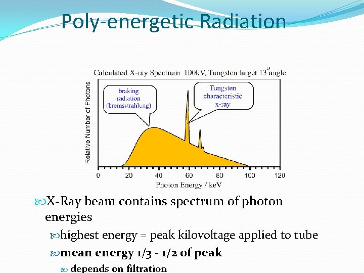
Poly-energetic Radiation X-Ray beam contains spectrum of photon energies highest energy = peak kilovoltage applied to tube mean energy 1/3 - 1/2 of peak depends on filtration
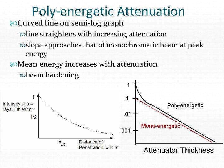
X-Ray Beam Attenuation reduction in beam intensity by absorption (photoelectric) deflection (scattering) Attenuation alters beam quantity quality higher fraction of low energy photons removed Beam Hardening Lower Energy Higher Energy
Half Value Layer (HVL) Absorber thickness that reduces beam intensity by exactly 1/2 Units of thickness value of x which makes N equal to No / 2 N = No e -mx N/No= 0. 5 = e -mx X 1/2 = HVL =. 693 / m
Half Value Layer (HVL) Indication of beam quality Valid for all beam types Mono-energetic Poly-energetic Higher HVL means more penetrating beam lower attenuation coefficient
Factors Affecting Attenuation Energy of radiation / beam quality higher energy more penetration less attenuation Matter density atomic number electrons per gram higher density, atomic number, or electrons per gram increases attenuation
Poly-energetic Attenuation Curved line on semi-log graph line straightens with increasing attenuation slope approaches that of monochromatic beam at peak energy Mean energy increases with attenuation beam hardening 1. 1 Poly-energetic Fraction. 01 Transmitted. 001 Mono-energetic Attenuator Thickness
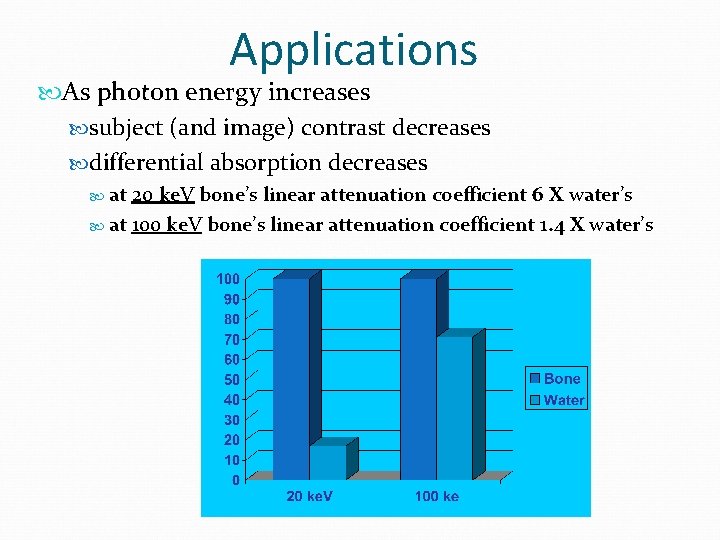
Applications As photon energy increases subject (and image) contrast decreases differential absorption decreases at 20 ke. V bone’s linear attenuation coefficient 6 X water’s at 100 ke. V bone’s linear attenuation coefficient 1. 4 X water’s
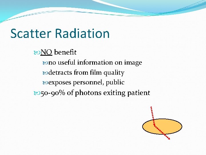
Scatter Radiation NO benefit no useful information on image detracts from film quality exposes personnel, public 50 -90% of photons exiting patient
Scatter Factors affecting scatter field size thickness of body part k. Vp An increase in any of above increases scatter.
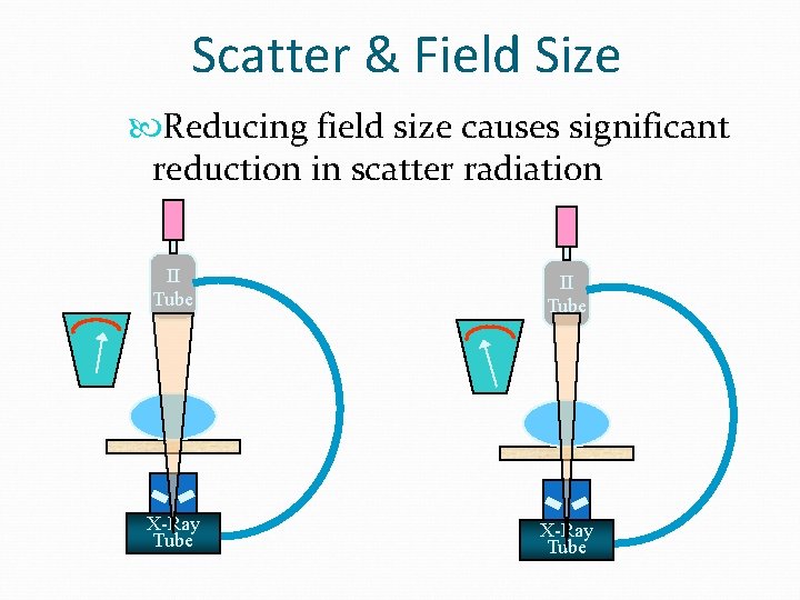
Scatter & Field Size Reducing field size causes significant reduction in scatter radiation II Tube X-Ray Tube
Field Size & Scatter Field Size & thickness determine volume of irradiated tissue Scatter increase with increasing field size initially large increase in scatter with increasing field size saturation reached (at ~ 12 X 12 inch field) further field size increase does not increase scatter reaching film scatter shielded within patient
Thickness & Scatter Increasing patient thickness leads to increased scatter but saturation point reached scatter photons produced far from film shielded within body
Scatter Management Reduce scatter by minimizing field size within limits of exam thickness mammography compression
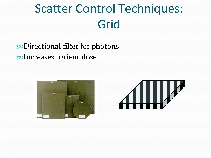
Scatter Control Techniques: Grid Directional filter for photons Increases patient dose
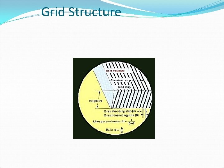
Grid Structure
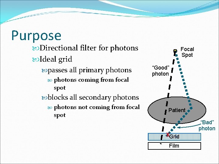
Purpose Directional filter for photons Ideal grid passes all primary photons spot coming from focal blocks all secondary photons not coming from focal spot Focal Spot “Good” photon Patient “Bad” photon XGrid Film
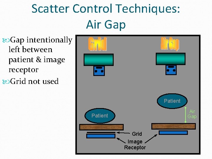
Scatter Control Techniques: Air Gap intentionally left between patient & image receptor Grid not used Patient Air Gap Patient Grid Image Receptor