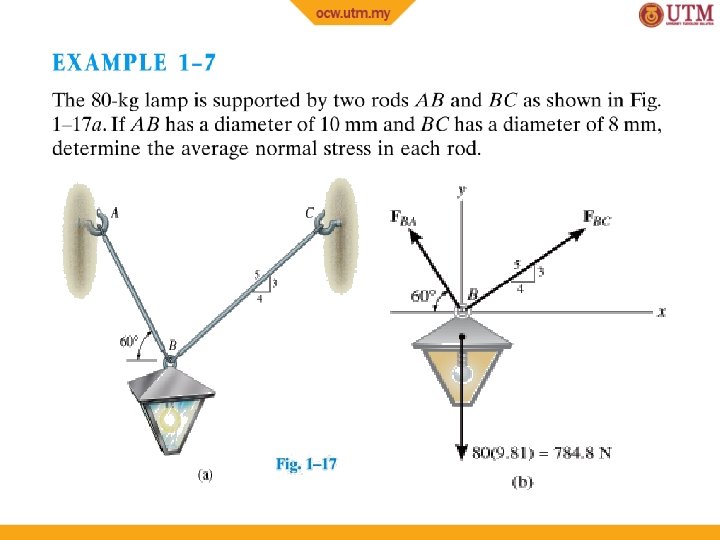
SKTN 2123 Strength of Materials Mohsin Mohd Sies


 Support Reactions • Consider segment CB Free-Body Diagram: Keep distributed")
 Free-Body Diagram: Intensity (w) of loading at C (by proportion)")
 Equilibrium equations: + ∑ Fx = 0; − Nc =")
 Equilibrium equations: Negative sign of Mc means it acts in")


 Internal loading Normal force diagram By inspection, largest loading area")
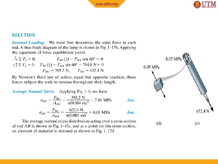
 Average normal stress σBC = PBC 30(103) N = 85.")


 Part (a) Internal loading Based on free-body diagram, Resultant loading")
 Part (a) Average stress Average normal stress, σ P 800")
 Part (a) Internal loading No shear stress on section, since")
 Part (b) Internal loading + ∑ Fx = 0; −")
 Part (b) Internal loading Or directly using x’, y’ axes,")
 Part (b) Average normal stress N 692. 8 N σ")
 Part (b) Average shear stress V 400 N τavg =")
 73")
 74")


 Draw free-body diagram: 89")
 Diameter of pins: 2. 84 k. N VA AA =")
 Diameter of pins: Choose a size larger to nearest millimeter.")
 Diameter of rod: 6. 67 k. N P ABC =")


- Slides: 112
SKTN 2123 Strength of Materials Mohsin Mohd Sies Nuclear Engineering, School of Chemical and Energy Engineering, Universiti Teknologi Malaysia
CHAPTER OBJECTIVES • Use the principles to determine internal resultant loadings in a body • Introduce concepts of normal and shear stress Discuss applications of analysis and design of members subjected to an axial load or direct shear
CHAPTER OUTLINE 1. 2. 3. 4. 5. 6. 7. Introduction Equilibrium of a deformable body Stress Average normal stress in an axially loaded bar Average shear stress Allowable stress Design of simple connections 3
• The main objective of the course is to provide the future engineer with the means of analyzing and designing various machines and load bearing structures. • Both the analysis and design of a given structure involve the determination of stresses and deformations. This chapter is devoted to the concept of stress. 4
1. 2 EQUILIBRIUM OF A DEFORMABLE BODY External loads • Surface forces – caused by the direct contact of one body with the surface of another. – Area of contact – Concentrated force – Linear distributed force – Centroid C (or geometric center) • Body force (e. g. , weight) – one body exerts a force on another without direct physical contact.
1. 2 EQUILIBRIUM OF A DEFORMABLE BODY Support reactions • for 2 D problems
1. 2 EQUILIBRIUM OF A DEFORMABLE BODY Equations of equilibrium • For equilibrium – balance of forces – balance of moments • • Draw a free-body diagram to account for all forces acting on the body Apply the two equations to achieve equilibrium state ∑F=0 ∑ MO = 0
1. 2 EQUILIBRIUM OF A DEFORMABLE BODY Internal resultant loadings • Define resultant force (FR) and moment (MRo) acting within the body (3 D): – Normal force, N – Shear force, V – Torsional moment or torque, T – Bending moment, M 8
1. 2 EQUILIBRIUM OF A DEFORMABLE BODY Internal resultant loadings • For coplanar (2 D) loadings: – Normal force, N – Shear force, V – Bending moment, M 9
1. 2 EQUILIBRIUM OF A DEFORMABLE BODY Internal resultant loadings • For coplanar loadings: – Apply ∑ Fx = 0 to solve for N – Apply ∑ Fy = 0 to solve for V – Apply ∑ MO = 0 to solve for M 10
1. 2 EQUILIBRIUM OF A DEFORMABLE BODY Procedure for Analysis • Method of sections 1. 2. 3. 4. Choose segment to analyze Determine Support Reactions Draw free-body diagram for whole body Apply equations of equilibrium 11
1. 2 EQUILIBRIUM OF A DEFORMABLE BODY Procedure for analysis • Free-body diagram 1. Keep all external loadings in exact locations before “sectioning” 2. Indicate unknown resultants, N, V, M, and T at the section, normally at centroid C of sectioned area 3. Coplanar system of forces only include N, V, and M 4. Establish x, y, z coordinate axes with origin at centroid 12
1. 2 EQUILIBRIUM OF A DEFORMABLE BODY Procedure for analysis • Equations of equilibrium 1. Sum moments at section, about each coordinate axes where resultants act 2. This will eliminate unknown forces N and V, with direct solution for M (and T) 3. Resultant force with negative value implies that assumed direction is opposite to that shown on free-body diagram 13
EXAMPLE 1. 1 Determine resultant loadings acting on cross section at C of beam. 14
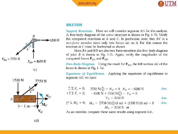
EXAMPLE 1. 1 (SOLN) Support Reactions • Consider segment CB Free-Body Diagram: Keep distributed loading exactly where it is on segment CB after “cutting” the section. Replace it with a single resultant force, F. 15
EXAMPLE 1. 1 (SOLN) Free-Body Diagram: Intensity (w) of loading at C (by proportion) w/6 m = (270 N/m)/9 m w = 180 N/m F = ½ (180 N/m)(6 m) = 540 N F acts 1/3(6 m) = 2 m from C. 16
EXAMPLE 1. 1 (SOLN) Equilibrium equations: + ∑ Fx = 0; − Nc = 0 + ∑ Fy = 0; Vc − 540 N = 0 Vc = 540 N + ∑ Mc = 0; −Mc − 504 N (2 m) = 0 Mc = − 1080 N·m 17
EXAMPLE 1. 1 (SOLN) Equilibrium equations: Negative sign of Mc means it acts in the opposite direction to that shown below 18
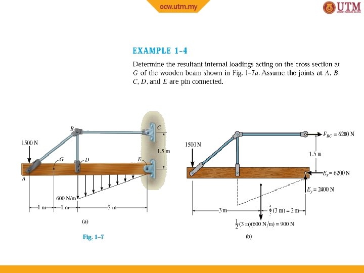
Review of Statics The structure is designed to support a 30 k. N load The structure consists of a beam and rod joined by pins (zero moment connections) at the junctions and supports Perform a static analysis to determine the internal force in each structural member and the reaction forces at the supports 19
Structure Free-Body Diagram Structure is detached from supports and the loads and reaction forces are indicated Conditions for static equilibrium: Ay and Cy can not be determined from these equations 20
Component Free-Body Diagram In addition to the complete structure, each component must satisfy the conditions for static equilibrium Consider a free-body diagram of the boom; substitute into the structure equilibrium equation Results: Reaction forces are directed along boom and rod 21
Method of Joints The boom and rod are 2 -force members, i. e. , the members are subjected to only two forces which are applied at member ends For equilibrium, the forces must be parallel to to an axis between the force application points, equal in magnitude, and in opposite directions Joints must satisfy the conditions for static equilibrium which may be expressed in the form of a force triangle: 22
Stress Analysis Can the structure safely support the 30 k. N load? From a statics analysis FAB = 40 k. N (compression) FBC = 50 k. N (tension) At any section through member BC, the internal force is 50 k. N with a force intensity or stress of d. BC = 20 mm From the material properties for steel, the allowable stress is Conclusion: the strength of member BC is adequate 23
1. 3 STRESS Concept of stress • To obtain distribution of force acting over a sectioned area • Assumptions of material: 1. It is continuous (uniform distribution of matter) 2. It is cohesive (all portions are connected together) 26
1. 3 STRESS Concept of stress • Consider ΔA in figure below • Small finite force, ΔF acts on ΔA 27
1. 3 STRESS Normal stress • Intensity of force, or force per unit area, acting normal to ΔA • Symbol used for normal stress, is σ (sigma) σz = lim ΔFz ΔA → 0 ΔA Tensile stress: normal force “pulls” or “stretches” the area element ΔA Compressive stress: normal force “pushes” or “compresses” area element ΔA 28
1. 3 STRESS Shear stress • Intensity of force, or force per unit area, acting tangent to ΔA • Symbol used for normal stress is τ (tau) τzx = τzy = lim ΔFx ΔA → 0 ΔA lim ΔFy ΔA → 0 ΔA 29
30
31
32
33
34
35
36
Prismatic bar • A prismatic bar or beam is a straight structural piece that has the same cross-section throughout its length
1. 4 AVERAGE NORMAL STRESS IN AXIALLY LOADED BAR Examples of axially loaded bar • Usually long and slender structural members • Truss members, hangers, bolts • Prismatic means all the cross sections are the same 38
1. 4 AVERAGE NORMAL STRESS IN AXIALLY LOADED BAR Assumptions 1. Uniform deformation: Bar remains straight before and after load is applied, and cross section remains flat or plane during deformation 2. In order for uniform deformation, force P be applied along centroidal axis of cross section 39
1. 4 AVERAGE NORMAL STRESS IN AXIALLY LOADED BAR Average normal stress distribution + FRz = ∑ Fxz ∫ d. F = ∫A σ d. A P = σA P σ= A σ = average normal stress at any point on cross sectional area P = internal resultant normal force A = x-sectional area of the bar 40
1. 4 AVERAGE NORMAL STRESS IN AXIALLY LOADED BAR Equilibrium • • • Consider vertical equilibrium of the element When the bar is stretched by the force P, the resulting stresses are tensile stresses If the force P cause the bar to be compressed, we obtain compressive stresses 41
1. 4 AVERAGE NORMAL STRESS IN AXIALLY LOADED BAR • Sign convention for normal stresses is: • (+) for tensile stresses and • (-) for compressive stresses • Because the normal stress σ is obtained by dividing the axial force by the cross–sectional area, it has units of force per unit of area. • In SI units: • Force is expressed in newtons (N) and area in square meters (m 2). A N/m 2 is a pascals (Pa). 42
1. 4 AVERAGE NORMAL STRESS IN AXIALLY LOADED BAR Maximum average normal stress • For problems where internal force P and xsectional A were constant along the longitudinal axis of the bar, normal stress σ = P/A is also constant • If the bar is subjected to several external loads along its axis, change in x-sectional area may occur • Thus, it is important to find the maximum average normal stress • To determine that, we need to find the location where ratio P/A is a maximum 43
1. 4 AVERAGE NORMAL STRESS IN AXIALLY LOADED BAR Maximum average normal stress • Draw an axial or normal force diagram (plot of P vs. its position x along bar’s length) • Sign convention: – P is positive (+) if it causes tension in the member – P is negative (−) if it causes compression • Identify the maximum average normal stress from the plot 44
1. 4 AVERAGE NORMAL STRESS IN AXIALLY LOADED BAR Procedure for Analysis Average normal stress • Use equation of σ = P/A for x-sectional area of a member when section subjected to internal resultant force P 45
1. 4 AVERAGE NORMAL STRESS IN AXIALLY LOADED BAR Procedure for Analysis Axially loaded members • Internal Loading: • Section member perpendicular to its longitudinal axis at pt where normal stress is to be determined • Draw free-body diagram • Use equation of force equilibrium to obtain internal axial force P at the section 46
1. 4 AVERAGE NORMAL STRESS IN AXIALLY LOADED BAR Procedure for Analysis Axially loaded members • Average Normal Stress: • Determine member’s x-sectional area at the section • Compute average normal stress σ = P/A 47
EXAMPLE 1. 6 Bar width = 35 mm, thickness = 10 mm Determine max. average normal stress in bar when subjected to loading shown. 48
EXAMPLE 1. 6 (SOLN) Internal loading Normal force diagram By inspection, largest loading area is BC, where PBC = 30 k. N 49
EXAMPLE 1. 6 (SOLN) Average normal stress σBC = PBC 30(103) N = 85. 7 MPa = (0. 035 m)(0. 010 m) A 50
1. 5 AVERAGE SHEAR STRESS • • Shear stress is the stress component that act in the plane of the sectioned area. Consider a force F acting to the bar For rigid supports, and F is large enough, bar will deform and fail along the planes identified by AB and CD Free-body diagram indicates that shear force, V = F/2 be applied at both sections to ensure equilibrium 53
1. 5 AVERAGE SHEAR STRESS Average shear stress over each section is: P τavg = A τavg = average shear stress at section, assumed to be same at each pt on the section V = internal resultant shear force at section determined from equations of equilibrium A = area of section 54
1. 5 AVERAGE SHEAR STRESS • Case discussed above is example of simple or direct shear • Caused by the direct action of applied load F • Occurs in various types of simple connections, e. g. , bolts, pins, welded material 55
56
57
1. 5 AVERAGE SHEAR STRESS Single shear • Steel and wood joints shown below are examples of single-shear connections, also known as lap joints. • Since we assume members are thin, there are no moments caused by F 58
1. 5 AVERAGE SHEAR STRESS Single shear • For equilibrium, x-sectional area of bolt and bonding surface between the two members are subjected to single shear force, V = F • The average shear stress equation can be applied to determine average shear stress acting on colored section in (d). 59
1. 5 AVERAGE SHEAR STRESS Double shear • The joints shown below are examples of doubleshear connections, often called double lap joints. • For equilibrium, x-sectional area of bolt and bonding surface between two members subjected to double shear force, V = F/2 • Apply average shear stress equation to determine average shear stress acting on colored section in (d). 60
Shearing Stress Examples Single Shear Double Shear 61
62
63
1. 5 AVERAGE SHEAR STRESS Procedure for analysis Internal shear 1. Section member at the pt where the τavg is to be determined 2. Draw free-body diagram 3. Calculate the internal shear force V Average shear stress 1. Determine sectioned area A 2. Compute average shear stress τavg = V/A 64
EXAMPLE 1. 10 Depth and thickness = 40 mm Determine average normal stress and average shear stress acting along (a) section planes a-a, and (b) section plane b-b. 65
EXAMPLE 1. 10 (SOLN) Part (a) Internal loading Based on free-body diagram, Resultant loading of axial force, P = 800 N 66
EXAMPLE 1. 10 (SOLN) Part (a) Average stress Average normal stress, σ P 800 N = 500 k. Pa σ= A = (0. 04 m) 67
EXAMPLE 1. 10 (SOLN) Part (a) Internal loading No shear stress on section, since shear force at section is zero. τavg = 0 68
EXAMPLE 1. 10 (SOLN) Part (b) Internal loading + ∑ Fx = 0; − 800 N + N sin 60° + V cos 60° = 0 + ∑ Fy = 0; V sin 60° − N cos 60° = 0 69
EXAMPLE 1. 10 (SOLN) Part (b) Internal loading Or directly using x’, y’ axes, + ∑ Fx’ = 0; N − 800 N cos 30° = 0 + ∑ Fy’ = 0; V − 800 N sin 30° = 0 70
EXAMPLE 1. 10 (SOLN) Part (b) Average normal stress N 692. 8 N σ = A = (0. 04 m)(0. 04 m/sin 60°) = 375 k. Pa 71
EXAMPLE 1. 10 (SOLN) Part (b) Average shear stress V 400 N τavg = A = (0. 04 m)(0. 04 m/sin 60°) = 217 k. Pa Stress distribution shown below 72
EXAMPLE 1. 11 (SOLN) 73
EXAMPLE 1. 11 (SOLN) 74
Bearing Stress in Connections Bolts, rivets, and pins create stresses on the points of contact or bearing surfaces of the members they connect. The resultant of the force distribution on the surface is equal and opposite to the force exerted on the pin. Corresponding average force intensity is called the bearing stress, 75
76
Pin Bearing Stresses To determine the bearing stress at A in the boom AB, we have t = 30 mm and d = 25 mm, To determine the bearing stress at A in the bracket, we have t = 2(25 mm) = 50 mm and d = 25 mm, 77
1. 6 ALLOWABLE STRESS Factor of safety considerations: uncertainty in material properties uncertainty of loadings uncertainty of analyses number of loading cycles types of failure maintenance requirements and deterioration effects importance of member to structures integrity risk to life and property influence on machine function 78
1. 6 ALLOWABLE STRESS • • • When designing a structural member or mechanical element, the stress in it must be restricted to safe level Choose an allowable load that is less than the load the member can fully support One method used is the factor of safety (F. S. ) Ffail F. S. = F allow 79
1. 6 ALLOWABLE STRESS • If load applied is linearly related to stress developed within member, then F. S. can also be expressed as: σfail F. S. = σallow τfail F. S. = τ allow In all the equations, F. S. is chosen to be greater than 1, to avoid potential for failure. Specific values will depend on types of material used and its intended purpose. 80
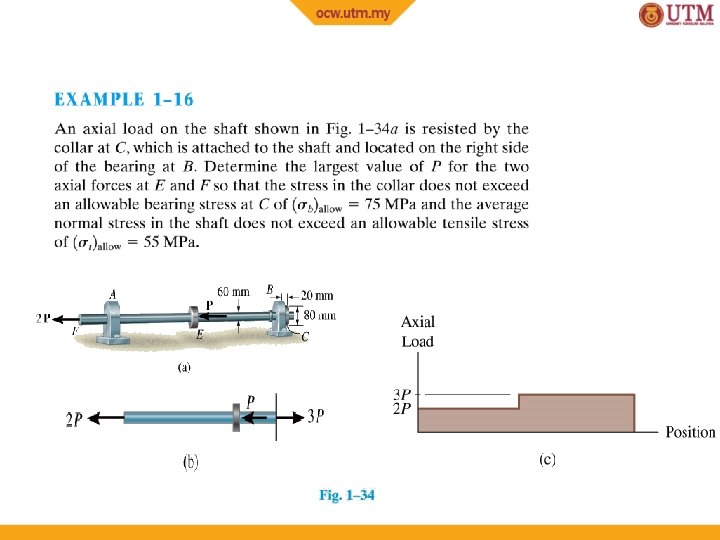
1. 7 DESIGN OF SIMPLE CONNECTIONS • To determine area of section subjected to a normal force, use P A= σ allow To determine area of section subjected to a shear force, use V A=τ allow 81
1. 7 DESIGN OF SIMPLE CONNECTIONS Cross-sectional area of a tension member Condition: The force has a line of action that passes through the centroid of the cross section. 82
1. 7 DESIGN OF SIMPLE CONNECTIONS Cross-sectional area of a connecter subjected to shear Assumption: If bolt is loose or clamping force of bolt is unknown, assume frictional force between plates to be negligible. 83
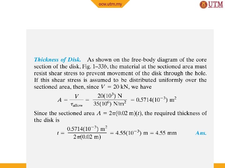
1. 7 DESIGN OF SIMPLE CONNECTIONS Required area to resist bearing • Bearing stress is normal stress produced by the compression of one surface against another. Assumptions: 1. (σb)allow of concrete < (σb)allow of base plate 2. Bearing stress is uniformly distributed between plate and concrete 84
1. 7 DESIGN OF SIMPLE CONNECTIONS Required area to resist shear caused by axial load • Although actual shear-stress distribution along rod difficult to determine, we assume it is uniform. • Thus use A = V / τallow to calculate l, provided d and τallow is known. 85
1. 7 DESIGN OF SIMPLE CONNECTIONS Procedure for analysis When using average normal stress and shear stress equations, consider first the section over which the critical stress is acting Internal Loading 1. Section member through x-sectional area 2. Draw a free-body diagram of segment of member 3. Use equations of equilibrium to determine internal resultant force 86
1. 7 DESIGN OF SIMPLE CONNECTIONS Procedure for Analysis Required Area • Based on known allowable stress, calculate required area needed to sustain load from A = P/τallow or A = V/τallow 87
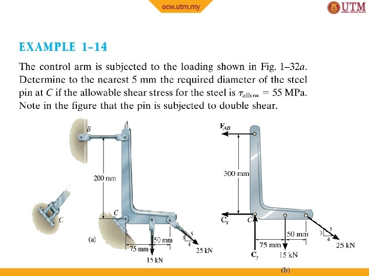
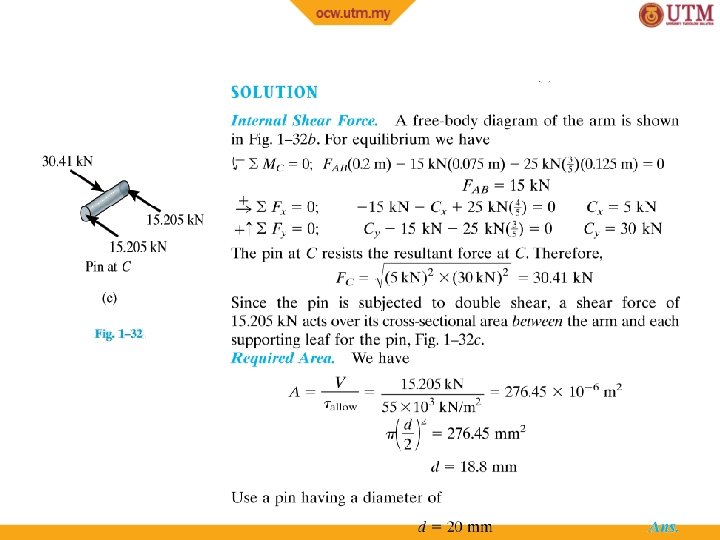
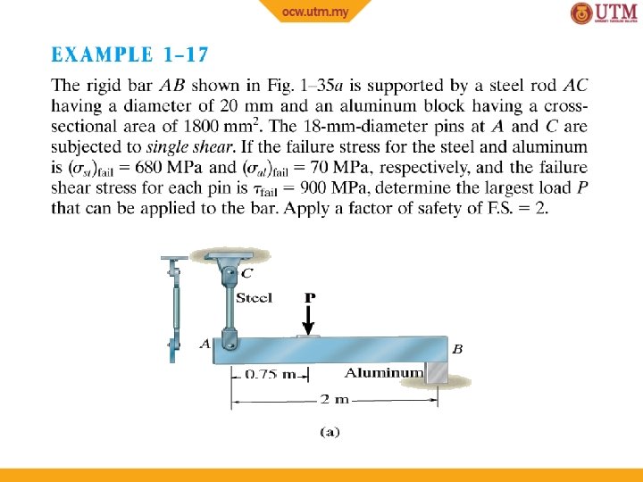
EXAMPLE 1. 13 The two members pinned together at B. If the pins have an allowable shear stress of τallow = 90 MPa, and allowable tensile stress of rod CB is (σt)allow = 115 MPa Determine to nearest mm the smallest diameter of pins A and B and the diameter of rod CB necessary to support the load. 88
EXAMPLE 1. 13 (SOLN) Draw free-body diagram: 89
EXAMPLE 1. 13 (SOLN) Diameter of pins: 2. 84 k. N VA AA = T = 90 103 k. Pa = 31. 56 10− 6 m 2 = (d. A 2/4) allow d. A = 6. 3 mm 6. 67 k. N VB − 6 m 2 = (d 2/4) AB = = 74. 11 10 B Tallow= 90 103 k. Pa d. B = 9. 7 mm 90
EXAMPLE 1. 13 (SOLN) Diameter of pins: Choose a size larger to nearest millimeter. d. A = 7 mm d. B = 10 mm 91
EXAMPLE 1. 13 (SOLN) Diameter of rod: 6. 67 k. N P ABC = = 115 103 k. Pa= 58 10− 6 m 2 = (d. BC 2/4) (σt)allow d. BC = 8. 59 mm Choose a size larger to nearest millimeter. d. BC = 9 mm 92
104
105
106
CHAPTER REVIEW • Internal loadings consist of 1. 2. 3. 4. • Normal force, N Shear force, V Bending moments, M Torsional moments, T Get the resultants using 1. method of sections 2. Equations of equilibrium 107
CHAPTER REVIEW • Assumptions for a uniform normal stress distribution over x-section of member (σ = P/A) 1. Member made from homogeneous isotropic material 2. Subjected to a series of external axial loads that, 3. The loads must pass through centroid of crosssection 108
CHAPTER REVIEW • Determine average shear stress by using τ = V/A equation – V is the resultant shear force on crosssectional area A – Formula is used mostly to find average shear stress in fasteners or in parts for connections 109
CHAPTER REVIEW • Design of any simple connection requires that – Average stress along any cross-section not exceed a factor of safety (F. S. ) or – Allowable value of σallow or τallow – These values are reported in codes or standards and are deemed safe on basis of experiments or through experience 110