Prepared by MADAM ROHAZITA BAHARI School of Bioprocess

Prepared by; MADAM ROHAZITA BAHARI School of Bioprocess Engineering

QR CODE 04102019
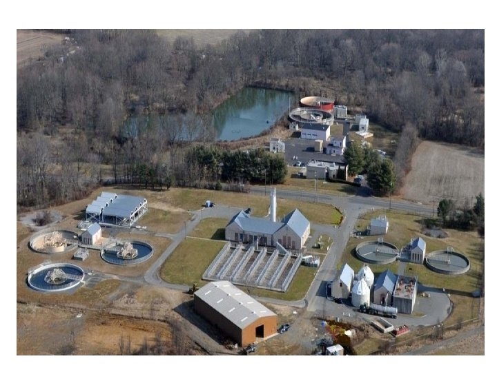

Waste Water Treatment Plant

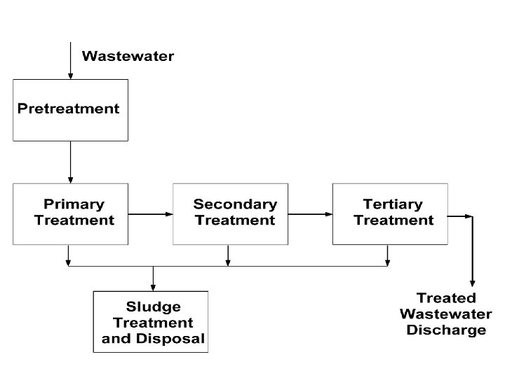
Steps of Waste Water Treatment 1. Collection of wastewater 2. Preliminary treatment (Physical treatment and clarification of large particle) 3. Primary treatment (physical treatment of smaller particles) 4. Secondary treatment (Biological treatment) 5. Tertiary treatment (Chemical treatment) 6. Sludge processing (Biological + chemical + physical) 7. Effluent discharge

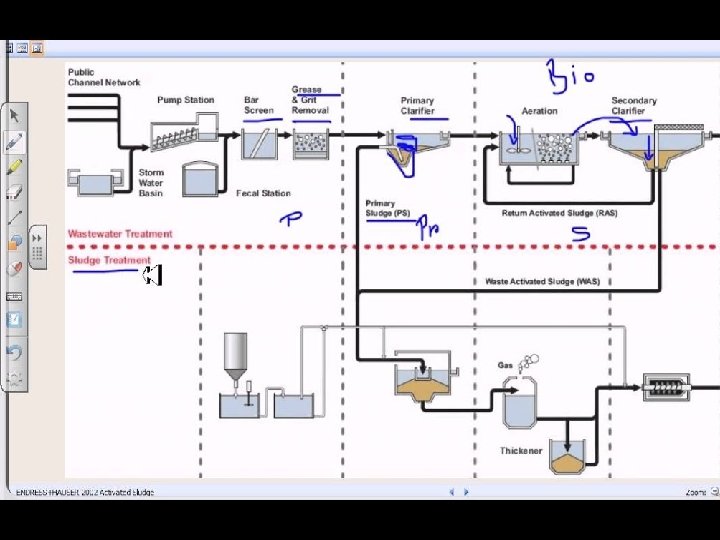
Steps of Waste Water Treatment • Collection of wastewater start with pump station the collecting on the sewage • Preliminary treatment (Physical treatment and clarification of large particle) Transferring from the preliminary treatment where involves different screeners with separate large particles Wastewater carries many impurities which solid partials through large solid particle, small solid particle include organic matters and chemical waste Depends on separation physical of solids from water (hard core separation) which design only to separate the large particles for ww.
 Primary")
Steps of Waste Water Treatment • Primary treatment (physical treatment of smaller particles) Primary treatment have the primary clarifier primary sedimentation tank where sludge produce. (same in secondary treatment) Physical treatment of smaller particles Using gravitation force for the solids to settle down to bottom of the settlement (in settling tanks)

Steps of Waste Water Treatment Typical Materials that are removal during primary treatment: Fats, oils, grease (aka FOG)/scum Sand, gravels (aka Grit) Larger settle able solids including human waste & floating materials • Primary treatment protects pump & equipment from damage • Main equipment in primary treatment is big tank, known as primary settlement tank • In sedimentation tank, need to reduce the flow of water, more slow more better sedimentation (because the water is flowing)
 Called biological treatment because")
Steps of Waste Water Treatment • Secondary treatment (Biological treatment) Called biological treatment because used microorganisms agents like bacteria, fungi and protozoa The water is full with organic compound acting as their media & microbes utilizing the media for their own throat Take off all organic components that present in ww & those organic components to grow themselves in turn they’re reducing the amount of organic compound in ww Will reduce the odor Heart of the wastewater treatment process secondary treatment have the secondary clarifier primary sedimentation tank where sludge produce. (same in primary treatment)
 wastewater treatment finally to")
Steps of Waste Water Treatment • Tertiary treatment (Chemical treatment) wastewater treatment finally to the effluent discharge center known as affluent purification. Means simply use chemical agents to purify Need to kill any other microorganism that present 1 st use gravity filter to separate bacteria, fungi etc. Then, treat the water to kill others Examples of chemical agents are ozone gas, chlorine etc. which using different mechanisms To reduce the odor as well as to kill any present microorganism that used in secondary treatment
 •")
Steps of Waste Water Treatment Sludge processing (involve Biological + chemical + physical) • What is Sludge : : anything which was present this wastewater which is the decomposed part of the organics as well as the bacterial dates & anything particle matter that we can see it settle down: :
 Sludge")
Steps of Waste Water Treatment Sludge processing (involve Biological + chemical + physical) Sludge from: q Primary sedimentation tank : when use the primary treatment process q Secondary sedimentation tank : when use the secondary treatment process All the components set it down to the bottom of the tank, known as : solid handling part of sludge

Steps of Waste Water Treatment Sludge processing generally condense the sludge to make it Thickening up the sludge, the digestion of the sludge by heating it and finally dehydrating and the sludge give a very calm compact portions/major nutrient Can use sludge to increase the fertility of the solid And use in land fields in agriculture purpose Effluent discharge The final product which the water is pure.

QR CODE 11/10/2019

Wastewat er Bar Rack/ Comminut or Grit Chamber Equalization Basin Primary Settling Biological Treatment Secondary Settling Advance Wastewater Treatment Refer Table 5 -1: Typical physical unit operations PRETREATMENT PROCESS PRIMARY PROCESS SECONDARY PROCESS TERTIARY PROCESS e. g: Depth Filter, Membrane filter, adsorption, Ion exchange, gas stripping etc

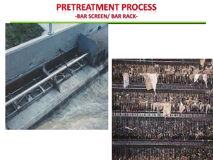
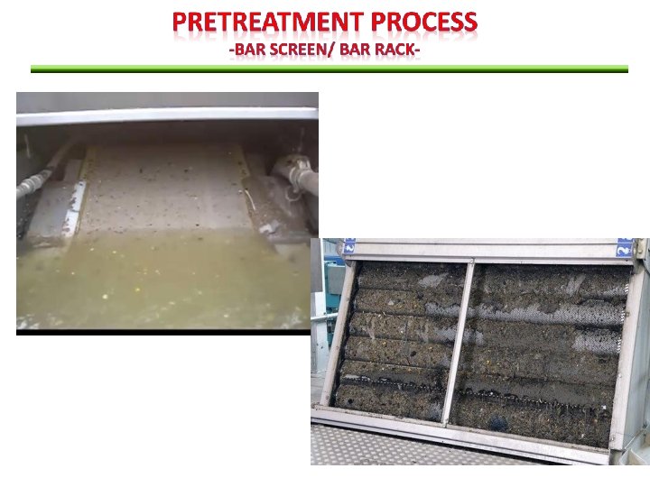
Retain solid found in influent WW to the treatment plant Principle role Coarse screen Remove coarse materials (e. g. sticks, rags, etc) from the flow stream that could : damage subsequent process equipment Screening Reduce overall treatment reliability & effectiveness process Contaminate waterway Fine screen place (used of/following in coarse screen) Where greater removals of solids are required to remove coarse materials (e. g. sticks, rags , etc) from the flow stream that could Protect process equipment Eliminate materials that may inhibit the beneficial reuse of biosolid
 perforated plate (fine screen)")
May consists of parallel bars, rods or wires (coarse screen) perforated plate (fine screen) The flow passes through the screen and the large solids are trapped on the bars for removal. Bar Screen/ Bar Rack The bar screen may be coarse (6 – 150 mm/ 0. 25 – 6 inch openings) or fine (< 6 mm/0. 25 inch openings). The bar screen may be manually cleaned or mechanically cleaned (performed frequently enough to prevent solids buildup and reduce flow into the plant)
 that tends to settle")
Remove grit (sand, egg shells or other heavy solid materials) that tends to settle in corners, bends, reducing flow capacity and ultimately clogging pipes and channels. Grit chamber are provided to Grit Chamber Protect moving mechanical equipment from abrasion Reduce formation of heavy deposits in pipelines, channels & conduits Reduce the frequency of digester cleaning caused by exessive accumulation of grit Grit removal processes use gravity/velocity, aeration or centrifugal force to separate the solids from the wastewater. The most common method of grit disposal is transport to a landfill. In some large plants, grit is incinerated with solids

Once screened, the wastewater passes into two aerated grit chambers. Lowpressure air entering the grit chamber creates a rolling motion that causes grit and dense solids to settle to the tank bottom.

used to intercept coarse solid & shred them in the screen channel The solids are cut up into a smaller, more uniform size of for return to the flow stream for subsequent removal. Comminutors & Macerators The use of comminutor and macerator is adventageous in a pumping station to: Protect pump againts clogging by rags & large objects Eliminate the need to handle & dispose of screenings However, shredded solid (plastic bags, rags) tends to form ropelike strands & can clog pump impellers, sludge pipelines & heat exchangers). Design consideration: • may be preceded by grit chambers to prolong life • Constructed with bypass arrangement

Macerators

• • • To minimize fluctuations in WW characteristics in order to provide optimum conditions for subsequence process To provide adequate dampening of organic fluctuations in order to prevent shock loading to biological system Provide adequate p. H control Provide cont. feed to biological system Provide capacity for controlled discharge To prevent high conc. of toxic materials from entering the biological treatment plants. Q Q t Bar Screen / communito r Grit Removal Equalization Basin t Primary Treatme nt Effluent for further treatment

In-line arrangement: • all of the flow passes through the equalization basin • Can be used to achieve considerable amount of constituent conc. and flowrate damping. Off-line arrangement: • Only flow above predetermined flow limit is diverted to equalization basin • Used to capture „first flush‟ from combined collection system

In-line and Off line equalization; • Both equalization system are both effective was to equalize flow volume. • But, in line equalization more effective for leveling out the variations in influent concentration because the entire flow is blended with the entire contents of the holding tank.
 Objectives: Prepare WW")
( primary & secondary process handle MOST of the NON-TOXIC wastewater) Objectives: Prepare WW for biological treatment (stabilize organic) Remove + 60% SS and 35% BOD 5 in sewage Important because the reduction of the suspended solids and BOD 5 1) lowers the O 2 demand, 2)decreases the rate of energy consumption and 3)Reduces operational problem with downstream biological treatment 4)remove scum (grease, oil, plastics, and other floatable materials) and inert particulate matter which are not removed in grit chamber Principle form of primary treatment: SEDIMENTATION Note: sedimentation tank = sedimentation basin, clarifier, settling basin, settling tank

Objectives: Speed up natural process of breaking down biodegradable organics Remove up to 85 % SS and BOD 5 Devices/structures: • Activated sludge, extended aeration, rotating biological contacting (RBC), trickling filter, aerated lagoons, sequencing batch reactor etc • Biological degradation of soluble organics. • Mostly aerobically in an open aerated vessels @ lagoon • Speed up natural processes of breaking down biodegradable organics • Cannot remove N, P, heavy metals, pathogens, bacteria and viruses. • After treatment, microorganism and other carried over solids are allowed to settle. • A fraction of sludge is recycle • Excess sludge along with sediment solids has to be disposed off.

Objectives: Nutrients removal, chlorination and dechlorination Process added after biological treatment in order to remove specific group/ types of residual Can remove + 95% BOD 5, P, SS, bacteria and N Devices/structures: • Filtration –removes Suspended Solid (SS) • Granular Activated Carbon – removes organics • Chemical oxidation – removes oxidizable organics • Expensive to process LARGE VOLUME of WW
 which is usually stated in")
What Is Suspended Solid, SS • Suspended Solids (SS) which is usually stated in conjunction with Biochemical Oxygen Demand (BOD). • The normal European discharge standard for SS is 35 mg/l and is usually quoted in short as ’ 25/35′ effluent (BOD of 25 mg/l & SS of 35 mg/l) • Therefore, most package sewage treatment plants will be designed to achieve at least ’ 25/35′ for a given populations Suspended solids are the solids visible in influent/effluent sewage which do not settle out easily over time. A more correct definition is; ‘A measurement of the solids in suspension in sewage, influents or effluents normally expressed in mg/l or parts per million (ppm). • Suspended Solids are normally reduced by both physical means such as settlement and also by biological treatment. A typical SS concentration in normal domestic effluent is 300 mg/l, which then needs to be reduce to 35 mg/l or better.

What Is Suspended Solid, SS To obtain very low Suspended Solids concentrations extra treatment such as with a Saran Filter or Package Media Filter might be necessary. A certain amount of BOD is attached to SS so reducing SS will also lead to a consequent decrease in BOD. An effluent with a low SS will look clear to the eye, while as the SS concentration begins to rise the effluent will become increasingly more cloudy

Depends on the degree of treatment required to bring the quality of raw wastewater to a permissible level of treated wastewater (eg. Effluent from the treatment plant) Selection of treatment process This ensures that the final effluent is either safe for disposal or acceptable for specific reuse or recycling. Other significant factor that will influence the selection of a treatment system Availability of funds and land at the treatment site The topography of land at the treatment site Non-availability of suitable mechanical equipment and skilled personnel for running and maintaining the plant. Ref: (Karia and Christian, 2006)

The points to keep in mind while selecting the treatment process Reduction of inorganic material component of wastewater is much easier and cheaper than removal of organics contents of wastewater Removal of suspended solids from wastewater requires lesser time and efforts than of colloidal and dissolved solids In many countries, the Environmental Protection Act requires at least the secondary treatment system for all publicly owned treatment works such as municipal wastewater treatment plant, so that effluent requirements of 30 mg/L for BOD and 100 mg/L of SS are achieved. Ref: (Karia and

Design criteria Strength & characteristics of WW Flow rate and their fluctuations Essential consideration Mass loading

Strength & characteristics of WW The strength of wastewater is normally expressed in terms of pollution load, which is determined from the concentrations of significant physical, chemical and biological content of wastewater. Characteristics of WW depend on the quality of water used by the community, culture of population, type of industries present & treatment given by industries to their WW. The strength of WW measured as mass per unit volume of WW (Units: mg/L ) If characteristics of raw WW show the concentration of specific constituents like BOD & SS within the standard permissible limits, there is no need to treat the WW.

Is the quantity or volume of wastewater in terms of rates FLOW RATE & THEIR FLUCTUATIONS It is the total quantity of wastewater generated daily and to be treated every day. The volume of WW depend on the water consumption by the population for its various activities The flow rate units: m 3/day or m 3/s or MLD (million Litres per Day) Normally a treatment plant is designed on the daily average flow basis which is known as plant capacity. Example: 1 MLD (Million Litres per Day) plant means = the plant designed for 1 – ML daily average flow of WW

The mass pollution load is defined as flow rate & strength of WW & is expressed as load per unit time MASS LOADING Example: WW having 1000 m 3/d flow & 200 mg/L (g/m 3) BOD has the mass pollution load of BOD equal to 200 kg/d (1000 m 3/d X 200 g/m 3 X 10 -3 g/kg) In the case of treatment plant that receives flow of combined sewerage system, the seasonal variation in the rainy season will lower down the BOD & SS concentration due to the dilution because of the added amount of storm water. On the other hand, a higher concentration of BOD & SS may be observed during the dry weather period. Therefore, in almost all cases, a flow-weighted average should be used because it is more accurate method of analysis

XW XQ Q i i i Where , XW = Xi = Qi flow –weighted average concentration on the constituent average concentration of the constituent during the “i” time period = average flow rate during “i” time period

The data determined through the research and laboratory scale model studies as well as those obtained from the operational experience of field and pilot scale WW treatment facility. The values of such guideline parameters are called design criteria and available in the literature. The most frequently assumed criteria for designing a conventional WW treatment plant (WWTP): • Detention period or time • Flow through velocity • Settling velocity • Surface loading rate @ over flow rate • Weir loading rate • Organic loading (BOD @ COD @ VSS loading) • Food to Microorganism ratio, F/M • Mean cell Residence Time • Hydraulic Loading • Volumetric Loading • Basin geometry (L: B: D) length, breadth and depth ratio.


Process of heavier solid particles in suspension, settle to the body of tank by gravity Removal of SS from WW Depends on Velocity of flow Size and shape of particles Sedimentation Viscosity of water Types of particles Discrete /non-flocculant particles Size & velocity constant during the settling Flocculant particles Size & velocity fluctuates during the settling Common operation & found almost in WWT plant LESS COSTLY than many other treatment processes

The settling of discrete particles can be analysed by means of the classic laws of sedimentation by Newton & Stokes. Gravitational force, Fg ( p w )g. Vp Frictional drag force, Fd Cd Ap w p 2 2

In the design of sedimentation basin, the settling velocities of the particles MUST be KNOWN. sedimentation The knowledge of settling velocity of particle is used to determining the depth of a treatment unit to separate the suspended solids (particulate matter) by gravity settling and for checking the adequacy of length or diameter of a tank to remove particles before the effluent flows out of the basin. vc Q A Where, vc = particle settling velocity Q = flowrate of WW A = surface of sedimentation tank

Outlet zone RECTANGULAR BASIN UPFLOW BASIN Settlin gzon e Sludge zone Outlet zone Inlet zone Outlet zone Sludge zone CIRCULAR BASIN Inlet zone Settlin g zone Outlet zone Inlet zone Idealized discrete particles settling in 3 different type of basins Settlin g zone

Circular Basin Rectangular Basin

Classification of particles settling Type 1 Discrete Type 3 Zone Type 2 Flocculant

Particles DOES NOT change in size, shape & density during the settling process Particles settle discretely at a constant velocity Settle as individual particles & do not flocculate Occurs during: Presedimentation for sand removal Grit Chamber

Flocculate during sedimentation Particles size constantly changing Settling velocity is changing increase with depth & extent of flocculation Occurs during: Alum or iron coagulation Primary sedimentation basins
 water")
The floc particles adhere together & the mass settle as a blanket (layer) water Solid settle Distinct clear zone & sludge zone present Concentration HIGH (greater than 500 mg/L) Occurs during: Activated sludge sedimentation Sludge thickeners

D A C D B D Initially, all the sludge is at uniform concentration A Compressio n Zone C B Transitio n Zone A A Transitio n zone High of sludge liq interfac e Dens e solid Settling Zone B Settling properties of flocculated sludge A settling proceeds, the collapsed solid on the bottom of the settling unit (D) build up at constant rate. C is zone of transition through which the settling velocity decreases Through the transition zone C, the settling velocity will decrease due to the increasing density & viscosity of the suspension surrounding the particles. When the rising layer of settle solid reaches the interface, a compression zone occur.

The following design criteria are generally assumed to design a Primary Settling Tank / Sedimentation A) GENERAL No. of Tanks 2 or more (usually) Types of tanks Circular or rectangular Removal of Sludge and Scum Mechanical (usually) Tank bottom slope 60 -150 mm/m Speed of sludge scraper 0. 02 – 0. 05 rpm
 DIMENSIONS Rectangular Tank Circular Tank Range Typical Length (m) 15 -100 30 Width")
B) DIMENSIONS Rectangular Tank Circular Tank Range Typical Length (m) 15 -100 30 Width (m) 3 -30 10 Depth 2. 5 -5 4 Diameter (m) 3 -60 30 Depth (m) 3 -5 4 Bottom slope, (mm/mm) 0. 02 – 0. 05 0. 03 C) TECHNICAL Range Typical Detention Time, t (hr) 1. 0 – 4. 0 2. 0 Flow Through velocity (m/min) 0. 6 – 3. 6 0. 9 SLR (m 3/m 2/hr) at average flow 1. 2 – 2. 5 1. 6 Peak Hourly Flow 2. 0 – 5. 0 4. 2 WLR (m 3/m/d) 125 - 500 250

Primarily used in WWT to separate solids from liquids in effluent streams. Types Clarifiers Criteria for sizing clarifier (settling tank) Tank depth at the side wall Detention time Overflow rate (surface loading rate) Scour velocity

Definition: The average daily flow rate divided by the surface area of the tank. Clarifiers Average daily flowrate (m 3/day) overflow rate @ surface settling rate (m 3/m 2 d) Q OR A Total surface area of the tank (m 2)

Depth of tank The water depth at the side wall measuring from the tank bottom to the top of the overflow weir. Exclude the additional depth resulting from slightly sloping bottom that is provided in both circular and rectangular clarifiers. Influen t Effluent weir Influen t H Occupie d sludge with Effluent weir loading (typical= 250 m 3/m. d) is equal to quantity of WW flowing divided by the total weir length, Lw Average daily flowrate (m 3/day) m 3 Q Effluent weir loading LW m. d Total weir length (m)

Detention time length of time a particle or a unit volume of WW remains in a reactor Detention time (day) td 3 = Tank volume (m ) Average daily flowrate (m 3/day) V Q

Scour Velocity horizontal velocity through the tank to avoid resuspension of settled particles VH 8 k ( s 1)gd f 1/ 2 Where: VH = horizontal velocity that will just produce scour (m/s) k = cohesion constant that depends on type of material being scoured (unitless) s=specific gravity of particles g=acceleration due to gravity (9. 81 m/s 2) d=diameter of particles f=Darcy-Weisbach friction factor (unitless)

Used for the removal of lighter SS, oil & grease. Flotation Also used to concentrate biological sludge and to separate both the fine solid and a liquid particles from the liquid phase Introducing fine gas (air) bubbles into the liquid phase. Bubbles will attach to the particulate matter , thus increase the buoyant force, cause the particle to rise to the WW surface. Floated particles are collected by skimming operation. Thus, the operation is just the opposite of that of gravity sedimentation where particles get removed at the bottom of the tank. Degree of particle removal can be enhanced by addition of chemical additives Advantage: Removal of smaller particles in a shorter time and more complete.

Example of Flotation System

Flotation system Systems Based on Formation of Air Bubbles Dispersed-Air flotation Frequently used in industrial WW treatment Vacuum flotation Systems based on recirculation of effluent Dissolved-Air flotation Frequently used in Municipal WW treatment Effluent is recirculation Effluent is not recycled

Systems Based on Formation of Air Bubbles Dispersed-Air flotation air bubbles are formed by introducing the air in the form of gas phase directly into the liquid phase either by a revolving impeller or through air diffusers at the atm pressure. Vacuum flotation WW is first saturated with air either directly in the aeration tank or by introducing air at the pump side (at Patm) Then partial vacuum is applied. This results in generation of small air bubbles which attached themselves to the particles and make them rise, forming a scum blanket. Typically a cylindrical tank maintain under vacuum is applied and continuously fed with WW Dissolved-air flotation Flotation is achieved first by dissolving the air in the WW or in a portion of treated effluent (liquid) under high pressure in the pressurizing or retention tank and then reducing the pressure of the WW through a pressure-reducing valve to atmospheric level during feeding it to the flotation tank to form the rising air bubbles.

Systems based on recirculation of effluent In large treatment plants, normally 15 -20% of the effluent is recycled Small treatment plants operate without recycling the effluent. Example: Dissolved-air Flotation (DAF) Effluent is recirculated A predetermine fraction of effluent from the flotation unit is taken to the pressurized tank where it is pressurized, and the air is dissolved below the saturation level. The flow is then mixed with the influent entering the flotation unit through a pressure-reducing valve sothat air bubbles come out from the recycled flow and get attached with the particles of incoming raw wastewater that are to be removed by flotation. Effluent is not recycled Wastewater influent is first retained for some time in the pressure tank where pressure of wastewater is increased to as high as 275350 k. Pa and air is dissolved in it. Then the flow is fed to the flotation unit through a pipeline having a pressurereducing valve. As the pressure is released from wastewater, the dissolved air comes out of the solution as fine bubbles which are used for particle separation by flotation.

Dispersed-Air Flotation
 Please refer diagram in your textbook")
Dissolved-Air Flotation (no recycle) Please refer diagram in your textbook

Concentration of particles to be removed Design consideration Particle rise velocity or buoyant force Quantity of air required formation of air bubbles Solids loading rate Air/solid ratio

Dissolved air flotation units are usually designed on the basis of the air to solid ratio, A/S, using the following equations: For system with recycle 1. 3 s ( f. P 1)R A � a S Sa Q Where, A S 1. 3 sa = = volume of air (ml) mass of solids (mg) weight of 1 ml of air (mg) solubility of air in (ml/L) (temp depended funct) Refer page 422 -423 For system without recycle A 1. 3 sa ( f. P 1) S Sa f = fraction of air dissolved at pressure P (atm) P = operating pressure (atm) Sa = influent suspended solids or sludge solids (mg/L) R = pressurized recycled flow (m 3/d) Q = mixed liquor flow (m 3/d)

Typical Design Criteria Hydraulic retention time, HRT Rising velocity of air-solid mix 20 -30 min (for efficient primary clarification) when no flocculants are used 2. 56 – 12. 7 cm/min when flocculants are used 20 – 60 cm/min Rising rate or surface loading rate 0. 06 – 1. 63 m 3/min-m 2

Employ for the removal of SS, following coagulation in physical-chemical treatment or as tertiary treatment following the biological WW treatment process Filtration SS are removed using granular filter medium (depth filter) principally by straining mechanism, consists of surface removal and depth removal Primary design/operating parameters Quality (SS conc. ) of effluent Headloss through the filter & accesories The efficiency of filtration process is depends on • character of media • character of SS • temperature • flow rate • bed depth • time (throughput volume) Note: Headloss is the reduction of total head or pressure drop of a liquid as it moves through a system.
")
The filter run terminates when: the total head loss reaches maximum point (high enough) excess SS or turbidity appears in the effluent. Filtration rate will effect : The build up of head loss the effluent quality attainable The head loss through the filter can be described by D‟Archy‟s Law V Kp hf L Where, V = superficial approach velocity (ft/min). Kp = coefficient of permeability (ft/min). This will change with time hf = frictional head loss (ft) L = depth of filter (ft).
 Effective Size (mm) Silica sand Ottawa sand Rounded")
Material Shape Relative Density Porosity (%) Effective Size (mm) Silica sand Ottawa sand Rounded Angular Spherical 2. 65 42 53 40 0. 4 -1. 0 Silica gravel anthracite Rounded 2. 65 40 1. 0 -5. 0 Angular 1. 5 -1. 7 55 0. 4 -1. 4 garnet angular 3. 1 -4. 3 46 0. 2 -0. 4 The selection of medium filters is depends on the type of filter and operation. See example in Table 11 -6, 11 -8, 11 -9

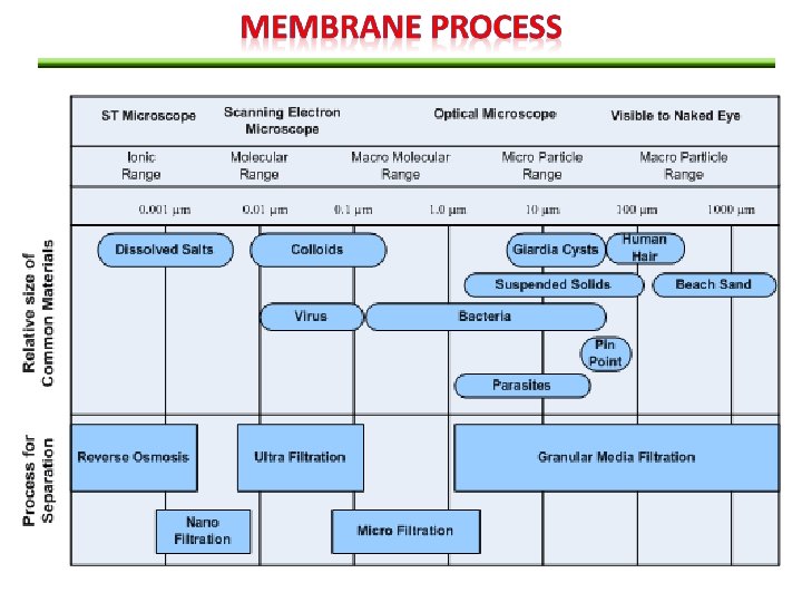
Use to separate dissolved and colloidal constituents from WW Components in water are driven through a membrane under the driving force of: concentration gradient pressure electrical potential Membrane Process The size of the opening in the membrane are a major determinant of species that can pass because the opening present a physical barrier to any substances that are larger than openings. A semi permeable membrane is SELECTIVE to the species it passes. Semi permeable membrane Permeate The liquid passing through the membrane Retentate The fraction not passing through the membrane.
 separation mechanism membrane’s material •")
Membrane process classification (Refer Table 11 -17 in textbook) separation mechanism membrane’s material • Thickness=0. 25μm, supported by porous substrate • Flat sheets, fine hollow fiber, or tubular form • For WW treatment, typically organic membrane. • E. g: polypropylene, cellulose acetate, aromatic polyamides and TFC • MF, UF = straining • NF = straining & diffusion • RO= diffusion size of separation • Macropores= >50 nm • Mesopores=2 -50 nm • Micropores= <2 nm • For RO = very fine pores, known as dense nature of driving force • Hydrostatic pressure difference (MF, UF, NF, RO) • concentration difference (dialysis)
 without reservoir")
Membrane Operation in MF and UF: Cross flow • 2 types: a) without reservoir b) with reservoir • Feed water is pumped with cross flow tangential to the membrane. • Water that does not pass through the membrane is recirculated after blending with additional feed water • Cross flow with resorvoir-water that does not pass through membrane is recirculated to storage tank. Direct feed or dead-end • No cross flow • All water applied to membrane passes through the membrane Refer page 1112 , Figure 11 -37.

OSMOTIC PRESSURE – balancing pressure difference between pressure and chemical potential , occur when two solutions having different solute conc. are separated by semipermeable membrane. REVERSE OSMOSIS (RO) –if a pressure gradient opposite in direction and greater than osmotic pressure, flow from the more concentrated to the less concentrated region will occur
; Qp Fw k w")
The flux of water through the membrane (Eq 11 -43); Qp Fw k w ( Pa ) A Where, Fw = flux of water (mass/area. time) A= area of the membrane kw = water mass transfer coefficient ∆Pa = average imposed pressure gradient ∆π=osmotic pressure gradient Qp = permeate stream flow

The flux of solute depends on the concentration gradient and resistance parameter. Q p. C p Fi ki Ci A Where, Fi= flux of solute, kg/m 2 s ki = solute mass transfer coefficient, m/s ΔCi = solute concentration gradient, kg/m 3 Cp = conc of solute in the permeate, kg/m 3 Qp = permeate stream flow, m 3/s A = membrane area, m 2 Membrane Process Rate of Rejection = C if Cip Ri , % � x 100 C if Measurement of the ability of membrane to reject the passage of a species i, Where, Ri = rejection rate Cif = conc of species i in the feed Cp = conc of species i in permeate

Fouling of a membrane increase resistance to flow and reduces the flux of water through a membrane Backwashing or chemical treatment may be applied to remove foulants. Membrane Process Irreversible fouling of membranes is the most serious problems. Oxidizing agents such as chlorine or ozone attack membranes and change their structures.
")
WW Treatment Plant (Top Glove Sdn. Bhd)
 WW – sludge decanter and filter press – to")
WW from production lines (unstable) WW – sludge decanter and filter press – to separate sludge (solid) and water, SOLID – jumbo beg, WW – recycle to the equalization tank Equalization Tank (to stabilize p. H, flowrate and pollutant concentration) Primary Clarifier -sludge is light, so scrapper is used to remove sludge Chemical Mixing Tank (Coagulation chemicals added to form precipitate ) Floculation Process -add chemicals to combine floc and form larger flocs Sludge – holding tank Buffer tank WW enter aeration tank (Biological treatment to reduce BOD, COD and other organic matter) Secondary Clarifier (continue process sludge removal) Sand filter Carbon filter Final Discharge

THANK YOU
- Slides: 83