MAXPLUS II 43 Complex PLD CPLD A PLD

 • A PLD that has several programmable sections with internal interconnections")


 • Device Dialog Box 67")
 • Figure 4. 20 MAX+PLUS II Compiler 세팅 • Figure 4. 21")
를 위 한 Programmer Object File(.")


 • Fig 4. 29 VHDL Port Modes • Fig 4. 30")


 LIBRARY ieee; USE ieee. std_logic_1164. ALL; ENTITY decode")
 ; 선택적 신호 할당문 -- decode 2 a.")

 97")
 98")


- Slides: 62
MAX+PLUS II 개요 43
Complex PLD (CPLD) • A PLD that has several programmable sections with internal interconnections between the sections. • In effect, CPLD is several interconnected PLDs on a single chip. 47
Altera Target Devices • 설계를 구현하기 위해 CPLDs를 사용한다. • MAX 7000 S family – EPM 7128 SLC 84 -7, 비 휘발성(non-volatile) CPLD, EEPROM 셀을 이용하여 프로그램. (128 : number of macrocells, S : in-system programmable) • FLEX 10 K family – EPF 10 K 20 RC 240 -4, 휘 발성(volatile) CPLD, LUT SRAM을 이용하 여 프로그램. 51
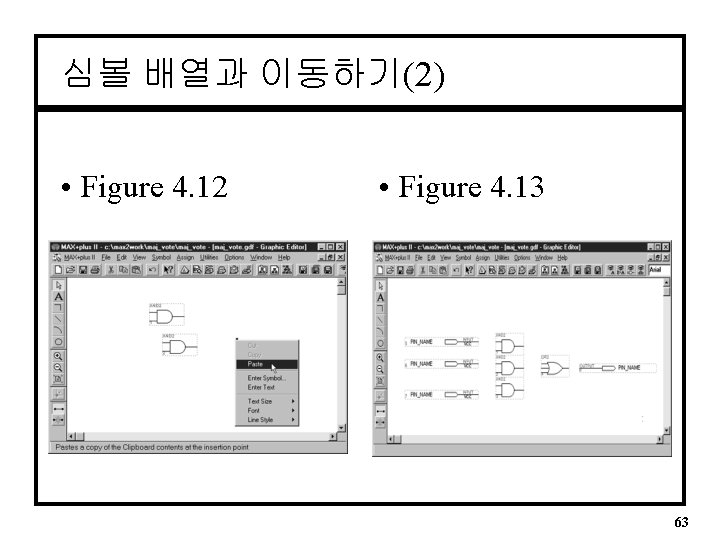
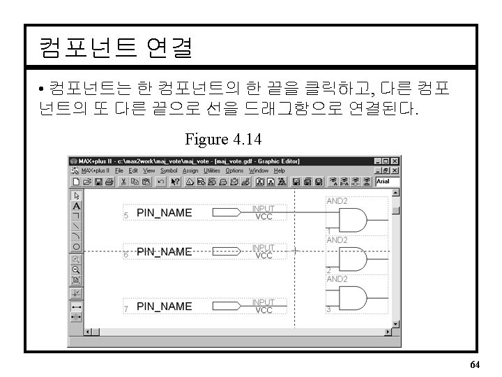
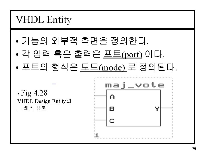
Figure 4. 3 • Majority Vote Circuit 55
Figure 4. 6 57
MAX+PLUS II Graphic Design Files 생성 • 먼저, 적절한 폴 더에 파일을 Save 하라. • 두 번째, Set Project to Current File. • Figure 4. 8 59
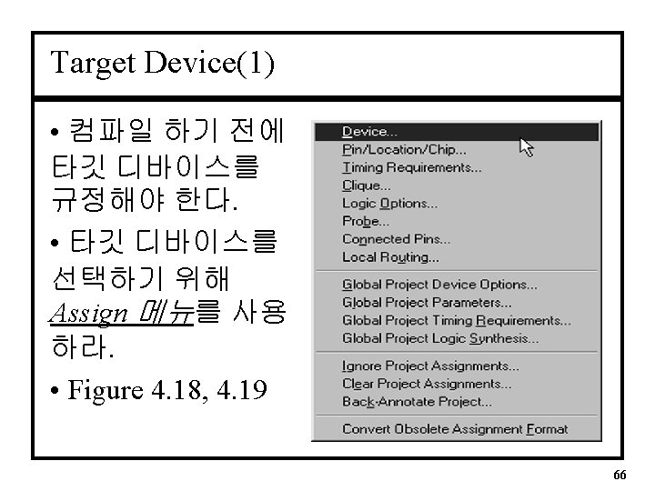
Target Device(2) • Device Dialog Box 67
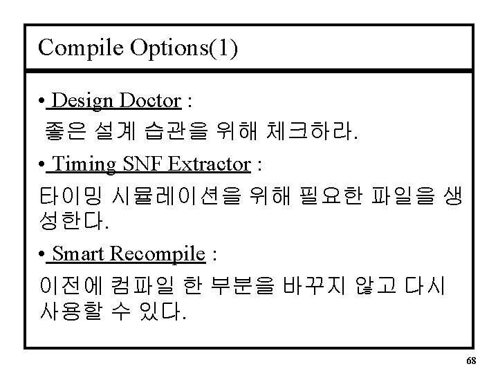
Compile Options(2) • Figure 4. 20 MAX+PLUS II Compiler 세팅 • Figure 4. 21 MAX+PLUS II Compiler 동작 69
Compile Files • non-volatile CLPDs (e. g. MAX series)를 위 한 Programmer Object File(. pof) 생성 • volatile CPLDs (e. g. FLEX series)를 위한 SRAM Object File (. sof) 생성 71
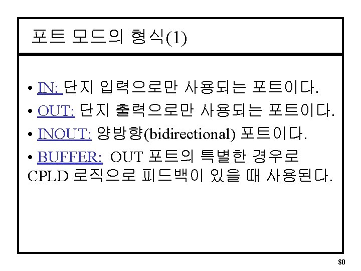
포트 모드의 형식(2) • Fig 4. 29 VHDL Port Modes • Fig 4. 30 BUFFER and OUT Modes 81
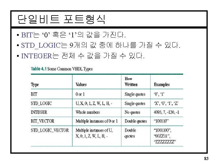
STD_LOGIC 형식 • 가능한 값: ‘U’ – uninitialized ‘X’ – forcing unknown ‘ 0’ – forcing 0 ‘ 1’ – forcing 1 ‘Z’ – high impedance ‘W’ – weak unknown ‘L’ – weak 0 ‘H’ – weak 1 ‘-’ – don’t care. • 일반적으로 ‘X’, ‘ 0’, ‘ 1’, ‘Z’가 사용된다. 84
Example - Majority Vote 2 LIBRARY ieee; USE ieee. std_logic_1164. ALL; ENTITY maj_vot 2 IS PORT( a, b, c y : IN STD_LOGIC; : OUT STD_LOGIC); END maj_vot 2; ARCHITECTURE majority OF maj_vot 2 IS BEGIN y <= (a and b) or (b and c) or (a and c); END majority; 90
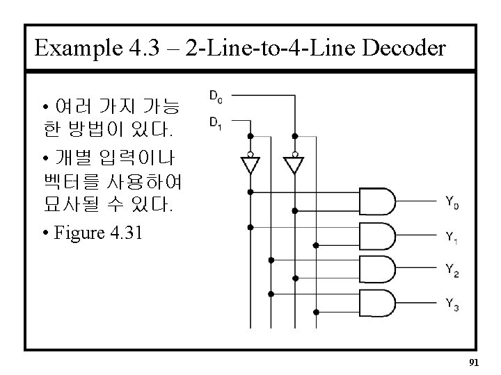
경우 1 – Separate variables LIBRARY ieee; USE ieee. std_logic_1164. ALL; ENTITY decode 1 IS PORT( d 1, d 0 : IN y 0, y 1, y 2, y 3 : OUT STD_LOGIC; STD_LOGIC); END decode 1; ARCHITECTURE decoder 1 OF decode 1 IS BEGIN y 0 <= (not d 1) and (not d 0); y 1 <= (not d 1) and ( y 2 <= ( d 1) and (not d 0); y 3 <= ( d 1) and ( d 0); END decoder 1; 93
경우 2 – Vectors(요소가 개별적으로 취급됨) LIBRARY ieee; USE ieee. std_logic_1164. ALL; ENTITY decode 2 IS PORT( d : IN STD_LOGIC_VECTOR (1 downto 0); y : OUT STD_LOGIC_VECTOR (3 downto 0)); END decode 2; ARCHITECTURE decoder 2 OF decode 2 IS BEGIN y(0) <= (not d(1)) and (not d(0)); y(1) <= (not d(1)) and ( y(2) <= ( d(1)) and (not d(0)); y(3) <= ( d(1)) and ( d(0)); END decoder 2; 94
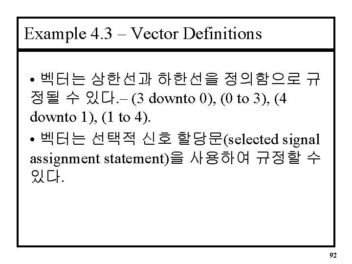
경우 3 – Vectors(요소가 그룹으로 취급됨) ; 선택적 신호 할당문 -- decode 2 a. vhd -- 4 -channel decoder -- Makes one and only one output HIGH for each binary combination of (d 1, d 0). LIBRARY ieee; USE ieee. std_logic_1164. ALL; ENTITY decode 2 a IS PORT( d : IN STD_LOGIC_VECTOR (1 downto 0); y : OUT STD_LOGIC_VECTOR (3 downto 0)); END decode 2 a; ARCHITECTURE decoder OF decode 2 a IS BEGIN -- Choose a signal assignment for y based on binary value of d -- Default case: all outputs deactivated WITH d SELECT y <= "1000" WHEN "00", "0100" WHEN "01", "0010" WHEN "10", "0001" WHEN "11", "0000" WHEN others; END decoder; 95
MAX+PLUS II VHDL Templates • VHDL structure를 생성하는 지름길을 마련 해준다. • Template 메뉴를 사용하여 이용 가능 하다. • Figure 4. 32 96
Creating a Physical Design • Pin Numbers 할당(1) 97
Pin Numbers 할당(2) 98
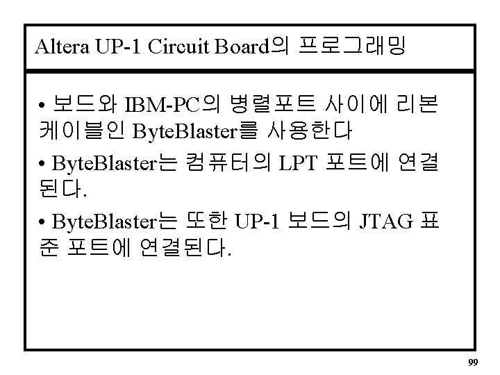
Byte. Blaster Download Cable 100
Altera UP-1 Circuit Board 101
Programming the Design 103
SUMMARY • The STD_LOGIC type can take on any of the following values: - ‘U’ ‘X’ ‘ 0’ ‘ 1’ ‘Z’ ‘W’ ‘L’ ‘H’ ‘-’ • STD_LOGIC is defined in a library called ieee. To use STD_LOGIC, include the following two statements at the beginning of a file. LIBRARY ieee; USE ieee. std_logic_1164. ALL; • A port in VHDL is an input or output. A signal is an internal connection like a wire. • Concurrent signal assignment statement : the simplest way to relate inputs and outputs in a VHDL EX) x <= (a and b) or c; • Selected signal assignment statement can act as a truth table in VHDL. 104