DEADLOCKS IN DISTRIBUTED OS UNIT 3 WHAT IS

DEADLOCKS IN DISTRIBUTED OS UNIT 3

WHAT IS A DEADLOCK? • A Deadlock is condition in which a set of processes can’t proceed further because the resource(s) necessary for progress of every process is held by some other process in the set. • ‘pehle aap, pehle aap’

CONDITIONS FOR DEADLOCK • Mutual exclusion. • No resource can be shared by more than one process at a time. • Hold and wait. • There must exist a process that is holding at least one resource and is waiting to acquire additional resources that are currently being held by other processes. • No preemption. • A resource cannot be preempted. • Circular wait. • There is a cycle in the wait-for graph.

DEADLOCK MODELING • Resource Allocation Graph • Nodes are resources/processes • Directed edges represent allocation or request • Existence of Cycle(s) signify Dead. Lock. P 1 P 2 Request Edge Allocation Edge P 3
 • Nodes are processes • Edges are requests for")
DEADLOCK MODELING • Wait-For-Graph (WFG) • Nodes are processes • Edges are requests for resources held by other processes • Existence of Cycle(s) signifies Dead. Lock. P 1 P 2 P 3 P 2

HOW TO HANDLE? • Deadlock Prevention • Difficult as we have to violate one of the 4 necessary conditions • Deadlock Avoidance • Difficult as we need some prior knowledge of resources required to ensure a Safe-State. • Deadlock Detection (Our Focus) • Feasible, as all we have to do is to find cycles and rollback some allocation. • However, deadlock detection algorithms must satisfy 2 conditions: • No undetected deadlocks. • No false-deadlocks.
 and checks")
DEADLOCK DETECTION • Centralized Approach • A coordinator constructs wait-for graph (WFG) and checks for directed cycles. • Ho-Ramamoorthy Phase 1 Algorithm • Ho-Ramamoorthy Phase 2 Algorithm • Distributed Approach • WFG is spread over different sites. • Obermarck’s Algorithm • Chandy-Misra-Haas Algorithm

HO-RAMAMOORTHY PHASE-1 ALGORITHM • Each node has 2 tables • Resource table • Resources locked by or waited on by processes. • Process table • Processes that have locked or are waiting for resources. • Coordinator periodically collects these tables from each site. • Coordinator constructs a WFG from processes common to both the tables. • No cycle, no deadlock. • A cycle means a deadlock

HO-RAMAMOORTHY PHASE-1 ALGORITHM Machine 0 R 1 Held by B A Wants Held by Machine 1 R 1 Wants C A R 3 R 2 Held by R 2 Wants R 3 Assume that B now asks for R 3. Coordinator B R 1 C R 3

HO-RAMAMOORTHY PHASE-1 ALGORITHM Machine 0 R 1 Held by B Wants Held by R 2 Wants R 3 A Coordinator C A R 3 R 2 Machine 1 R 1 Wants Held by R 1 B Assume that C now releases R 3 and then B asks for R 3. What if messages reach out of order? B R 1 C R 3

HO-RAMAMOORTHY PHASE-1 ALGORITHM • Drawbacks • This algorithm can detect Phantom Deadlocks. • A phantom deadlock means the detection of a false deadlock, a deadlock that doesn’t really exist but is falsely detected. • This algorithm also incurs high storage and communication costs.

HO-RAMAMOORTHY PHASE-2 ALGORITHM • To overcome the problem of Phantom Deadlocks, the algorithm has 2 phases. • Phase-1 is same. • In Phase-2, on detection of a deadlock, the nodes are again queried. • in a hope that messages will arrive in order. • Centralized algorithms suffer from • Single point failures • Scalability

DISTRIBUTED ALGORITHMS • Path-pushing • Resource dependency information is disseminated through paths (in the graph). • Edge-chasing • Special messages or probes are circulated along edges of WFG. • Deadlock exists if the probe is received back by the initiator.

OBERMARCK’S PATH PUSHING ALGORITHM • Each site maintains a local Wait-For Graph. • A virtual node ‘x’ exists at each site that represents external processes. • An edge (pi, px) is added if process pi is waiting for a resource held by a process in another site. • An edge (px, pj) is added if process pj in another site is waiting for a resource held by a process of this site. • When the deadlock detection process begins, • If a cycle is found at a site which doesn’t involve the external node ‘x’ it means the deadlock exists within the site and can be resolved locally. • If there exists a cycle involving ‘x’, it means a deadlock is possible that contains processes from other sites and hence they should be intimated.

OBERMARCK’S PATH PUSHING ALGORITHM 1 3 4 2 Node S 1 1 3 Node S 2 5

OBERMARCK’S PATH PUSHING ALGORITHM 1. At S 1, p 1 is waiting for a resource held by p 3 in S 2, (p 1, px) 2. At S 1, p 3 is a process in S 2 waiting for resource held by a process in S 1, (px, p 3) 3. If a cycle exists but doesn’t involve x, then it can be solved locally. 4. A Cycle (px, 3, 2, 1, px) exists and hence the message is forwarded to Site S 2. 1 x 1 3 4 2 3 Node S 1 4 2 Node S 1 1 3 Node S 2 5

OBERMARCK’S PATH PUSHING ALGORITHM 1. At S 2, p 3 is waiting for a resource held by p 2 in S 1, (p 3, px) 2. At S 2, p 1 is a process in S 1 waiting for resource held by process in S 2, (px, p 1) 3. When the message is received by S 2, the edges within the received cycle that don’t involve px are added. 4. Cycle (px, 3, 2, 1, px); thus (3, 2) and (2, 1) is added. 5. Now a cycle (without x) exists and should be resolved. x 1 3 2 Node S 2 5

OBERMARCK’S PATH PUSHING ALGORITHM • It is used for databases where transactions lock and wait on resources. • The downside of the algorithm is that • Multiple deadlock detections may be initiated simultaneously, which results in multiple recoveries leading to overkill. • Extra Message Overhead. • Detection is complicated wherein the processes span over many nodes.

CHANDY-MISRA-HAAS EDGE CHASING ALGORITHM • It uses a probe message to detect the presence of cycles. • The blocked process sends the probe message. • The message contains three variables. • The Id of the blocked process, • The Id of the process sending the message, and • The Id of the process to which the message was sent. • The probe is forwarded to the processes holding the requested resources and continues that way. • If the blocked process receives its own probe, it means that a cycle exists and hence the deadlock also exists.
 Machine 0 0 (0, 0, 1) 1")
CHANDY-MISRA-HAAS EDGE CHASING ALGORITHM (0, 8, 0) Machine 0 0 (0, 0, 1) 1 2 (0, 1, 2) 0 is locally dependent upon 1 (0, 2, 3) Machine 1 (0, 3, 4) 4 3 5 (0, 3, 5) 2 is remotely dependent upon 3 (0, 4, 6) (0, 5, 7) Machine 2 6 7 (0, 6, 8) 8

READING ASSIGNMENT • Distributed systems: principles and paradigms • by AST & MV Steen • Chapter 3 • 3. 5. DEADLOCKS IN DISTRIBUTED SYSTEMS • 3. 5. 1. Distributed Deadlock Detection • Centralized Deadlock Detection • Distributed Deadlock Detection • 3. 5. 2. Distributed Deadlock Prevention • 3. 6. SUMMARY

THREADS UNIT 3

WHAT IS A PROCESS? • We are multi-tasking systems. • Computers achieve this via the notion of a Process • Each process represents a distinct job. • The scheduling algorithms let a process run for some time and then preempt it to allow other processes to run. • During preemption the context of the current process is saved and the context of old process is restored for execution. • However, processes are heavy-weight.

WHAT IS A PROCESS? • Heavy-Weight Process • They are normal processes that don’t share memory with other processes. Process 1 Process 2 Program Counter DATA STACK CODE Shared Variable DATA STACK CODE • In other words, they have private CODE, STACK, DATA, PC, etc. • Lets save their context? • What about shared variable?

WHAT IS A THREAD? • Every ‘Heavy Weight’ process has a single thread of execution. • main() in a C program. • Consider that we want to have 2 or more copies of same program running at the same time. • 2 distinct processes. • Lot of information needs to be maintained. • The IPC is costly. • Threads are ‘Light Weight’ processes which have their own private STACK & PC while share CODE, DATA and other resources with other threads of same process. • Thus the basic unit of computation becomes Thread not process.

WHAT IS THREAD? Process 1 Thread 2 Program Counter STACK DATA CODE Scheduling and forking a new process means saving and creating DATA, CODE, STACK, etc. However, in case of threads only PC & STACK is involved.

WHAT IS A THREAD? • Threads are executed concurrently like processes. • Threads are scheduled like processes • PC & STACK • Threads behave like processes • Can fork() new threads • All Threads belonging to same process share DATA & CODE while threads from different processes do not. • Consider your MS-WORD • Spelling Check Thread • Grammar Check Thread • Consider a Browser • • Marquee Animation Text Entry Download

CHARACTERISTICS OF A THREAD? • Share Address Space • Access Global Variables • Access Global Functions • Private Stack • Own Local Variables • Share Other resources • Open Files • Ports int sum(int x, int y) { return x+y; }

ADV. & DIS-ADV. OF A THREAD • Data Sharing • Low IPC • Little Creation time • Only STACK & PSW • Little Switching Overhead • STACK & PSW • Parallelism with sequential execution and blocking system calls • Ease of programming • Flaw • One thread can interfere with another running thread due to common address space. • However, all threads of a process are owned by same user.

THREAD USAGE • Threads can be used in 3 configurations • Dispatcher-Worker Model • Team Model • Pipe-line Model

DISPATCHER-WORKERS MODEL Consider a File Server example wherein Dispatcher receives block requests And Worker Threads do actual read/write. Requests Worker thread Dispatcher thread Identical Threads Requests Monolithic Process

TEAM MODEL Consider a server that exports multiple services and each thread services a Requests unique request. Thread Identical or Non-Identical Threads

PIPELINE MODEL Requests Consider a server that reads/writes Encrypted Files Thread Non-Identical Threads Thread

THREAD DESIGN ISSUES • A thread package is a set of primitives that a thread based system provides to manipulate threads. • 5 Issues • • • Thread Creation Thread Termination Thread Synchronization Thread Scheduling Signal Handling

THREAD CREATION • Static Approach • No. of threads/process is pre-defined during compilation and the count is fixed for its entire running period. • Fixed Stack/Thread at the time of creation • Dynamic Approach • No. of threads/process is dynamic • Dynamic Stack/Thread • Creation should take care of following • Thread Identifier • Scheduling priority

THREAD TERMINATION • A Thread may exit itself or can be killed by another thread/process. • All threads belonging to a single process terminate as soon as the main thread (parent) exits

THREAD SYNCHRONIZATION • Because they share DATA, 2 or more threads can access a shared variable simultaneously. • Synchronization is mandatory for serialized access. • Mutex • Binary semaphore • Lock, if unlocked, to get exclusive access otherwise block & queue. • Unlock when done • They are Atomic Operations

THREAD SYNCHRONIZATION • Condition Variables • Appropriate for co-operating threads • Makes use of mutex • If the mutex is locked, the process sends wait signal for the resource and blocks. • When the resource becomes free, the running process sends signal to the waiting process to get hold of the mutex.
 Fails Wait (mutex) Unlock(mutex) Signal (mutex)")
THREAD SYNCHRONIZATION Thread 1 Thread 2 Lock (mutex) Fails Wait (mutex) Unlock(mutex) Signal (mutex) Lock (mutex)

THREAD SCHEDULING • Priority • FIFO or Round-Robin • Pre-Emptive or Non-Preemptive • Flexibility • Varying Quantum Size • E. g. single thread is running • Handoff execution to another thread in a Queue • E. g. Fibers in Windows • Affinity • Anticipating the cache hit if run on same MPU again

SIGNAL HANDLING • Signals correspond to • Interrupts • Exceptions • Signals should be handled in context of any executing thread. • Exception handler in every process • Signals shouldn’t get lost due to its occurrence in another thread. • Exception Signaling Variable / Thread

READING ASSIGNMENT • Distributed systems: principles and paradigms • by AST & MV Steen • Chapter 4 • • • 4. 1. THREADS 4. 1. 1. Introduction to Threads 4. 1. 2. Thread Usage 4. 1. 3. Design Issues for Threads Packages 4. 1. 4. Implementing a Threads Package • Implementing Threads in User Space • Implementing Threads in the Kernel • Scheduler Activations • 4. 1. 5. Threads and RPC

SYSTEM MODELS IN DS UNIT 3

SYSTEM MODELS • The Workstation Model • The Processor Pool Model

WORKSTATION MODEL • The workstation model • workstations scattered throughout a building and connected by a high-speed LAN. • In workstation model, the systems can be • diskfull workstations • diskless workstations.

DISKLESS WORKSTATION • The workstations don’t have private disks rather the file system is located on one or more centralized remote file servers • Makes workstations cheaper • Easy maintenance of binaries • New releases are available to all by updating it at one place • Simple Backup and hardware(disk) maintenance • Symmetry and flexibility • Access files from any workstation • Advantage • low cost, easy hardware and software maintenance, symmetry and flexibility • Disadvantage • heavy network usage • file servers may become bottlenecks

DISKFULL WORKSTATIONS • Workstations in this model have private disks • They can be used in 4 ways: • Paging and temporary files • It reduces communication cost but increases monetary cost • Paging, temporary files, and system binaries • It further reduces communication cost but increases monetary cost and cost of updating binaries • Paging, temporary files, system binaries, and file caching • More reduction in comm. cost but can lead to cache inconsistency • Complete local file system • No network load but goes against the philosophy of DS

IDLE WORKSTATION • 30% of workstations are idle • A simple solution • • rsh machine command Explicitly mention the machine The program executes in a different environment The actual user may start using the idle machine • Three key issues • How to locate an idle machine? • How to execute it? • What to do if owner comes back?

LOCATING IDLE WORKSTATION • Server driven • The server announces by registering itself as idle in a central registry • or broadcasting its state which is maintained by each client in their local registry • Client driven • The client broadcasts a request asking machines about their state • The idle machines reply • Depending upon workload, the responses are delayed

LOCATING IDLE WORKSTATION Registry List of idle workstation registrar 4. Deregister 2. Request idle Workstation, get reply Home machine remote 3. Claim machine 5. Set up environment 6. Start process 9. Notify originator 1. Machine registers when it goes idle Idle workstation 7. Process runs manager 8. Process exits

EXECUTE THE PROCESS • The process will have to run in same environment as that of Home workstation • Environment includes • Working directory • Binaries • System Calls and much more • File System READ & WRITE should be directed to Home station or centralized server. • Similarly, read from keyboard and write to the screen must be directed to home station. • However, other calls like malloc(), etc. can be executed on remote machine

NOW, OWNER COMES BACK • Abrupt KILL • We will lose the work and can lead to inconsistency in File System • Warn & KILL • Migrate • Good but technically not feasible • Lots of kernel data structures are involved • N/W ports, RPCs, etc. • What about children? • Let the owner fork() his processes • Perceived performance degradation

THE PROCESSOR POOL MODEL • A processor pool is a set of processors which can be dynamically allocated to users on demand. • It is like taking the concept of disk-less workstations a step further. • Assume • Request Input rate λ • Processor processing rate µ • Stable operation, µ > λ • However, if λ > µ, then the queue will grow without bound.
![THE PROCESSOR POOL MODEL • The mean response time T=1/(µ - λ) [Kleinrock, 1974]](http://slidetodoc.com/presentation_image_h/bdfb626e8a87c79ed34cb3b7012a59f2/image-54.jpg "THE PROCESSOR POOL MODEL • The mean response time T=1/(µ - λ) [Kleinrock, 1974]")
THE PROCESSOR POOL MODEL • The mean response time T=1/(µ - λ) [Kleinrock, 1974] • Now, if there are n processors, • each with request input rate λ, and • processing rate µ, • then we can pool them to reduce the mean response time. • Mean response time will be • T’=1/(nµ -nλ)=(1/n)T

HYBRID MODEL • Provide each user with a personal workstation and a processor pool in addition. • For the hybrid model, even if you can not get any processor from the processor pool, at least you have the workstation to do the work.

READING ASSIGNMENT • Distributed systems: principles and paradigms • by AST & MV Steen • Chapter 4 • • • 4. 2. SYSTEM MODELS 4. 2. 1. The Workstation Model 4. 2. 2. Using Idle Workstations 4. 2. 3. The Processor Pool Model 4. 2. 4. A Hybrid Model

PROCESSOR ALLOCATION IN DS UNIT 3

PROCESSOR ALLOCATION • How to allocate processes to processors? • Load Distribution • Non-migratory (Static) • When a process is allocated to some processor, then no matter how overloaded the machine is, it will stay there. • Migratory (Dynamic) • When a process is allocated some processor, then depending upon the workload the process can be migrated.

GOALS OF ALLOCATION • Maximize CPU utilization • Minimize mean response time • Minimize Response ratio • The amount of time it takes to run a process on some machine, divided by how long it would take on some unloaded benchmark processor.

DESIGN ISSUES IN ALLOCATION ALGORITHMS • Deterministic vs heuristic algorithms • Centralized vs distributed algorithms • Optimal vs suboptimal algorithms • Local vs global algorithms • Sender-initiated vs receiver-initiated algorithms

DETERMINISTIC VS HEURISTIC • Deterministic Algorithms are appropriate when everything about the process is known • Computing requirements • Comm. requirements, • File I/O • Approximation is sometimes used to work with deterministic algorithm • E. g. Airline Reservation • Heuristic Algorithms are appropriate when the load is completely unpredictable

CENTRALIZED VS DISTRIBUTED • Centralized Algorithms make use of a coordinator for allocation. • Distributed Algorithms don’t use any coordinator • Information is spread over multiple nodes

OPTIMAL VS SUB-OPTIMAL • Are we trying to find out the best allocation or the acceptable one? • Heuristic + Distributed + Sub-optimal

LOCAL VS GLOBAL • Whether or not the process can be run when created? • If NO, then send it to some other machine • Local Algorithm • If NO, try to get information about other nodes and then only send it to some appropriate node • Global Algorithm

SENDER-INITIATED VS RECEIVER-INITIATED • Whether an overloaded machine sends a request for help or not? • Sender initiated • Whether the under loaded machine announces for help or not? • Receiver initiated

READING ASSIGNMENT • Distributed systems: principles and paradigms • by AST & MV Steen • Chapter 4 • • • 4. 3. PROCESSOR ALLOCATION 4. 3. 1. Allocation Models 4. 3. 2. Design Issues for Processor Allocation Algorithms 4. 3. 3. Implementation Issues for Processor Allocation Algorithms 4. 3. 4. Example Processor Allocation Algorithms

FILE SYSTEMS UNIT 3

WHAT IS A FILE SYSTEM? • Collection of on-disk structures & algorithms • Sometimes, in-core & on-disk • Generally at Kernel level • Sometimes at User-mode level • Basic file functions • Sometimes advanced • Generally on disk • Sometimes on other permanent media & volatile media

HISTORY • File systems were considered part of the OS • DEC Tape (184 kilobytes per tape on the PDP-8) • 1972, Gary Kildall • Working on PL/M • Created CP/M (3 ½ K, 8 characters, 3 extension) • Digital Research • usage of CP/M was tripling every year. • Tim Patterson • “QDOS” (Quick and Dirty Operating System) • 16 -bit CP/M • Bill Gates bought Tim Patterson’s QDOS for $50, 000 • Renamed it MS-DOS • FAT name was coined

WHAT EXACTLY IS A FILE SYSTEM? • An Abstraction • Persistent Storage • It allows data to stored for long term • Hierarchical Namespace • It identifies data by names (filenames) • It provides large namespace (path) • APIs • It provides clean interface to manipulate data

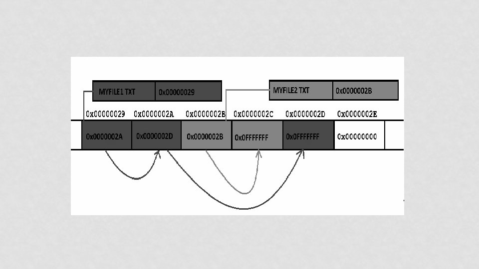
BUT HOW IT WORKS? • Example of FAT 32 file system • It consists of 4 different parts • • BOOT Sector FAT (File Allocation Table) Directory Structure Clusters

OK! THEN HOW IT WORKS!!! • Kernel code checks for volumes • Uses Entries in PT & signatures in Boot sector to identify the type • Loads appropriate code (ALGORITHMS) • This code mounts the file system at some specific point (Drive in Win, Folder in *nix) • Creates in-core structures to map on-disk structures
 Directory Module File Module Access Control Module Maps")
FILE SYSTEM STRUCTURE fopen(“c: abc. txt”) Directory Module File Module Access Control Module Maps File Names to File IDs Maps File IDs to actual files Validates the access File Access Module Reads & Writes Data/Metadata Block Module Allocates & Accesses Disk Blocks Device Module Disk I/O, I/O level caching

READING ASSIGNMENT • Papers: • A Quick Review of On-Disk Layout of Some Popular Disk File Systems • By Wasim Ahmad Bhat & SMK Quadri • Review of FAT Data Structure of FAT 32 file system • By Wasim Ahmad Bhat & SMK Quadri

DISTRIBUTED FILE SYSTEMS UNIT 3

WHAT IS DFS? • It is a client/server-based application that allows clients to share, access and process data stored on the server(s) as if it were on their own computer. • What about FTP? • User gets copy of the file! • Needs to know address of the server!! • Is it a concrete file system? • Generally NO!!!

DFS - GOALS • Goal: • To provide common view of centralized file system, but distributed implementation. • Ability to open & update any file on any machine on network • Handle all synchronization issues and capabilities of shared local files • Thus, the goal is to manage a set of dispersed storage devices to look & work like one.

DFS - REQUIREMENTS • Basically only two: • access transparency, and • location transparency • However, other requirements have become mandatory; • • • performance, scalability, concurrency control, fault tolerance, and security

Client Computer Server 1 Servers may be running 3 different concrete file systems (FAT, ext 4, LFS) on top Server. DFS 2 runs of which Server 3

WHAT ABOUT NAMING? • 3 schemes: • combination of host and local name • • guarantees a unique name But NOT location transparent & location independent. DFS is a loose collection of independent file systems. E. g. Windows Network • Mount remote directories to local directories • Coherent directory structure & location independent • E. g. Unix/Linux with NFS; Windows with mapped drives • Total integration of component file systems. • A single global name structure spans all the files in the system.

A COMPARISON Sharing Main memory File system Distributed file system Web Persistence Distributed Consistency Example cache/replicas maintenance 1 1 RAM UNIX file system Sun NFS Web server

FILE SERVICE • A file service is a specification of what the file system offers to clients. • A file server is the implementation of a file service and runs on one or more machines.

DISTRIBUTED FILE SERVICE REQUIREMENTS • • Transparency Concurrency Replication Heterogeneity Fault tolerance Consistency Security Efficiency

TRANSPARENCY • Access: • Local/Remote file should be accessed in the same manner • Mobility: • Automatic relocation of files should be possible • Location: • Same namespace after relocation of files • Performance: • Programs should continue to perform satisfactorily • Scaling: • Expanding the service to meet additional loads should be transparent

CONCURRENCY • File-level or record-level locking • Other forms of concurrency control

REPLICATION • For better load-sharing & response, multiple identical copies of files may be maintained
 any OS or")
HETEROGENEITY • Service can be accessed by clients running on (almost) any OS or hardware platform. • Design must be compatible with the file systems of different OSes • Service interfaces must be open • precise specifications of APIs are published.

FAULT TOLERANCE • Service must continue to operate even when clients make errors or crash. • Service must resume after a server machine crashes. • If the service is replicated, it can continue to operate even during a server crash.

CONSISTENCY • Unix offers one-copy update semantics for operations on local files. • Single cached copy • Difficult to achieve the same for distributed file systems while maintaining good performance and scalability. • Multiple caches (performance) • Multiple physical copies (scalability & reliability)

SECURITY • Must maintain access control and privacy as for local files. • based on identity of user making request • Identities of remote users must be authenticated • Privacy requires secure communication • Service interfaces are open to all processes not excluded by a firewall. • vulnerable to impersonation and other attacks

EFFICIENCY • Goal for distributed file systems is to perform comparable to local file system.

READING ASSIGNMENT • Distributed systems: principles and paradigms • by AST & MV Steen • Chapter 5 • • 5 Distributed File Systems 5. 1. DISTRIBUTED FILE SYSTEM DESIGN 5. 1. 1. The File Service Interface 5. 1. 2. The Directory Server Interface • Naming Transparency • Two-Level Naming • 5. 1. 3. Semantics of File Sharing

DIS. FILE SERVICE COMPONENTS UNIT 3

DISTRIBUTED FILE SERVICE COMPONENTS • Structuring the file service as three components: • A flat file service • A directory service • A client module.

DISTRIBUTED FILE SERVICE COMPONENTS Client computer Application Server computer Directory service Flat file service Client module

FLAT FILE SERVICE • Concerned with the implementation of operations on the contents of file. • Unique File Identifiers (UFIDs) are used to refer to files in all requests for flat file service operations. • UFIDs are long sequences of bits chosen so that each file has a unique number among all of the files in a distributed system.

DIRECTORY SERVICE • Provides mapping between text names for the files and their UFIDs. • Clients may obtain the UFID of a file by quoting its text name to directory service. • Directory service supports functions needed generate directories, to add new files to directories.

CLIENT MODULE • It runs on each computer and provides integrated service (flat file and directory) as a single API to application programs. • For example, in UNIX hosts, a client module emulates the full set of Unix file operations. • It holds information about the network locations of flat-file and directory server processes.

DIS. FILE SERVICE TYPES UNIT 3

FILE MODELS • Structured vs Unstructured • Un-Structured – Stream of bytes • Structured - Stream of records • Mutable vs Immutable • In-place updates • Out-of-place updates

FILE ACCESSING MODELS • Remote Service Model • Data-Caching Model • Cache consistency problem • Upload/Download Model

DATA TRANSFER MODELS • File-Level Transfer • Block Level Transfer • Record Level Transfer • Byte Level Transfer

OTHER DFS DESIGN CONSIDERATIONS UNIT 3

CACHE CONSISTENCY • Reduce network traffic by retaining recently accessed disk blocks in local cache • In memory cache • Small files, diskless workstations • In disk cache • Large files, sustains server failure • Cache-consistency problem • keeping the cached copies consistent with the master file, especially on write operations

CACHE UPDATE • Write through • Reliable but hinders performance • Delayed-write • Write operations complete quickly; • some data may be overwritten in cache, saving needless network I/O. • Poor reliability • unwritten data may be lost when client machine crashes • Inconsistent data • Solution: scan cache at regular intervals and flush dirty blocks

SERVER SEMANTICS • Stateless Service • Avoids maintaining state information in server by making each request self-contained. • No need to establish and terminate a connection by open and close operations. • Poor support for locking or synchronization among concurrent accesses • E. g. NFS

SERVER SEMANTICS • Stateful Service • • • Client opens a file (as in Unix & Windows). Server fetches information about file from disk, stores in server memory, Returns to client a connection identifier unique to client and open file. Identifier used for subsequent accesses until session ends. Server must reclaim space used by no longer active clients. • Increased performance; fewer disk accesses.

REPLICATION • Replicas of the same file reside on independent machines. • Improves availability and can shorten service time. • Naming scheme maps a replicated file name to a particular replica. • Existence of replicas should be invisible to higher levels. • Replicas must be distinguished from one another by different lower-level names. • Updates • Replicas of a file denote the same logical entity • Update to any replica must be reflected on all other replicas.

SUN NFS UNIT 3

SUN-NFS : A DISTRIBUTED FILE SYSTEM • Developed by Sun Microsystems in the 1980 s to allow any computer to access files residing on any other computer connected via a network. • The motivation • share files across heterogeneous machines. • The design goal • provide this service without having to modify, or even recompile, programs accessing these files. • In addition, Unix file access semantics and reasonable performance had to be ensured.

SUN-NFS : ARCHITECTURE • It consists of three software components: • one that resides on top of some concrete file system (such as UFS) on the server and exports directories as NFS shares to clients; • another that hooks to the Virtual File System (VFS) on the client machine to abstract the NFS share on the server as a local concrete file system; • and finally, the communication protocol between the NFS server and NFS client.

SUN-NFS : ARCHITECTURE

SUN-NFS: AN EXAMPLE Server A sees : /users/ steen/mbox Client A sees: /remote/vu/ mbox Client B sees: /work/me/ mbox

READING ASSIGNMENT • Distributed systems: principles and paradigms • by AST & MV Steen • Chapter 5 • • • 5. 2. DISTRIBUTED FILE SYSTEM IMPLEMENTATION 5. 2. 1. File Usage 5. 2. 2. System Structure 5. 2. 3. Caching Cache Consistency 5. 2. 4. Replication Update Protocols 5. 2. 5. An Example: Suns Network File System NFS Architecture NFS Protocols NFS Implementation • 5. 2. 6. Lessons Learned

REFERENCES • Books: • Distributed systems: principles and paradigms • by AST & MV Steen • Distributed OS (Concepts & Design) • by PK Sinha • Papers: • A SURVEY OF DISTRIBUTED FILE SYSTEMS • by M. Satyanarayanan • The design & implementation of SUN NFS • by Sandberg et al. • Understanding and mitigating security issues in Sun NFS • by Wasim A. B. & S. M. K. Quadri
- Slides: 116