Chapter 4 Network Layer Computer Networking A TopDown


- Slides: 121
Chapter 4 Network Layer Computer Networking A Top-Down Approach These slides are based on the slides made available by Kurose and Ross. © All material copyright 1996 -2012 J. F Kurose and K. W. Ross, All Rights Reserved 6 th edition Jim Kurose, Keith Ross Addison-Wesley March 2012 Network Layer 4 -1
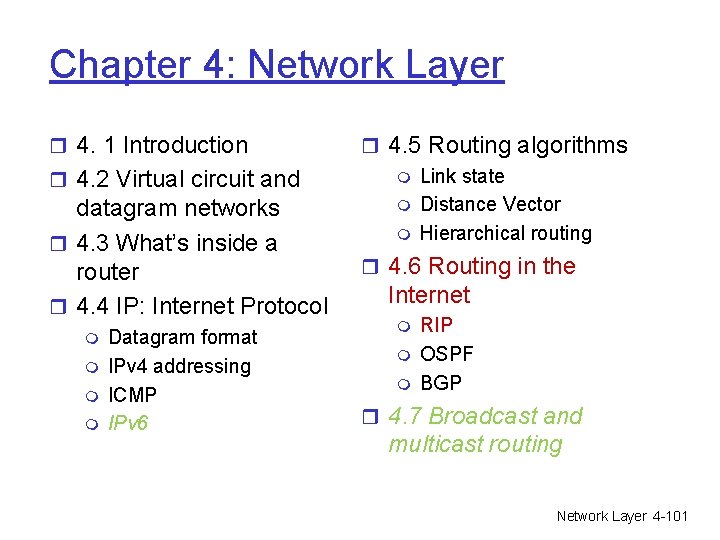
Chapter 4: Network Layer r 4. 1 Introduction r 4. 2 Virtual circuit and datagram networks r 4. 3 What’s inside a router r 4. 4 IP: Internet Protocol m m Datagram format IPv 4 addressing ICMP IPv 6 r 4. 5 Routing algorithms m Link state m Distance Vector m Hierarchical routing r 4. 6 Routing in the Internet m m m RIP OSPF BGP r 4. 7 Broadcast and multicast routing Network Layer 4 -2
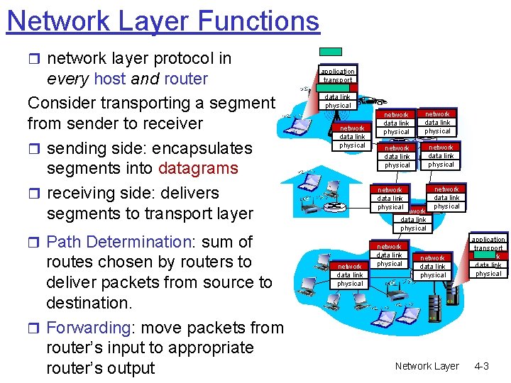
Network Layer Functions r network layer protocol in every host and router Consider transporting a segment from sender to receiver r sending side: encapsulates segments into datagrams r receiving side: delivers segments to transport layer application transport network data link physical network data link physical network data link physical r Path Determination: sum of routes chosen by routers to deliver packets from source to destination. r Forwarding: move packets from router’s input to appropriate router’s output network data link physical Network Layer application transport network data link physical 4 -3
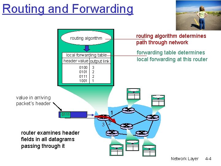
Routing and Forwarding routing algorithm determines path through network routing algorithm forwarding table determines local forwarding at this router local forwarding table header value output link 0100 0101 0111 1001 3 2 2 1 value in arriving packet’s header 0111 1 3 2 router examines header fields in all datagrams passing through it Network Layer 4 -4
Chapter 4: Network Layer r 4. 1 Introduction r 4. 2 Virtual circuit and datagram networks r 4. 3 What’s inside a router r 4. 4 IP: Internet Protocol m m Datagram format IPv 4 addressing ICMP IPv 6 r 4. 5 Routing algorithms m Link state m Distance Vector m Hierarchical routing r 4. 6 Routing in the Internet m m m RIP OSPF BGP r 4. 7 Broadcast and multicast routing Network Layer 4 -5
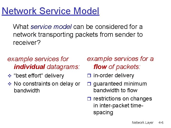
Network Service Model What service model can be considered for a network transporting packets from sender to receiver? example services for individual datagrams: example services for a flow of packets: v “best effort” delivery r in-order delivery v No constraints on delay or r guaranteed minimum bandwidth to flow r restrictions on changes in inter-packet timespacing Network Layer 4 -6
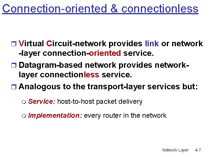
Connection-oriented & connectionless r Virtual Circuit-network provides link or network -layer connection-oriented service. r Datagram-based network provides networklayer connectionless service. r Analogous to the transport-layer services but: m Service: host-to-host packet delivery m Implementation: every router in the network Network Layer 4 -7
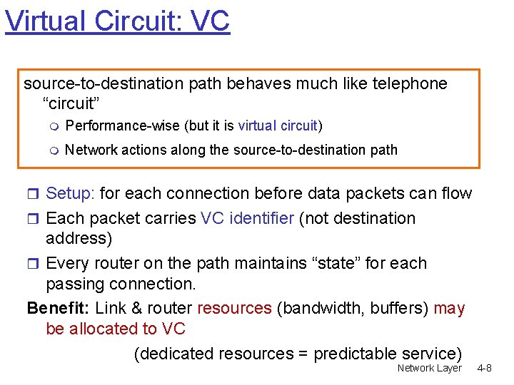
Virtual Circuit: VC source-to-destination path behaves much like telephone “circuit” m Performance-wise (but it is virtual circuit) m Network actions along the source-to-destination path r Setup: for each connection before data packets can flow r Each packet carries VC identifier (not destination address) r Every router on the path maintains “state” for each passing connection. Benefit: Link & router resources (bandwidth, buffers) may be allocated to VC (dedicated resources = predictable service) Network Layer 4 -8
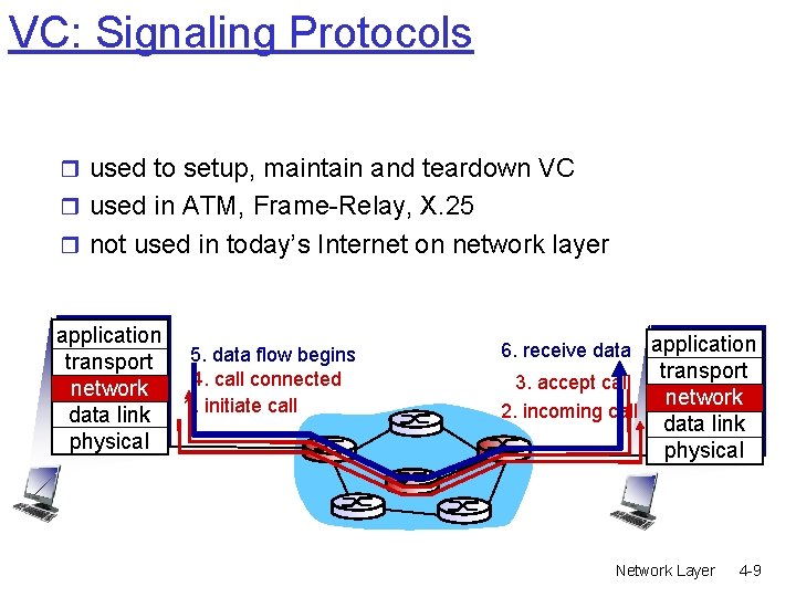
VC: Signaling Protocols r used to setup, maintain and teardown VC r used in ATM, Frame-Relay, X. 25 r not used in today’s Internet on network layer application 5. data flow begins transport 4. call connected network data link 1. initiate call physical 6. receive data application 3. accept call 2. incoming call transport network data link physical Network Layer 4 -9
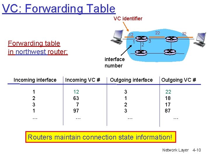
VC: Forwarding Table VC identifier 22 12 Forwarding table in northwest router: 1 2 32 3 interface number Incoming interface 1 2 3 1 … Incoming VC # 12 63 7 97 … Outgoing interface 3 1 2 3 Outgoing VC # 22 18 17 87 … … Routers maintain connection state information! Network Layer 4 -10
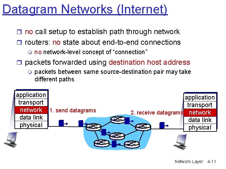
Datagram Networks (Internet) r no call setup to establish path through network r routers: no state about end-to-end connections m no network-level concept of “connection” r packets forwarded using destination host address m packets between same source-destination pair may take different paths application transport network 1. send datagrams data link physical application transport 2. receive datagrams network data link physical Network Layer 4 -11
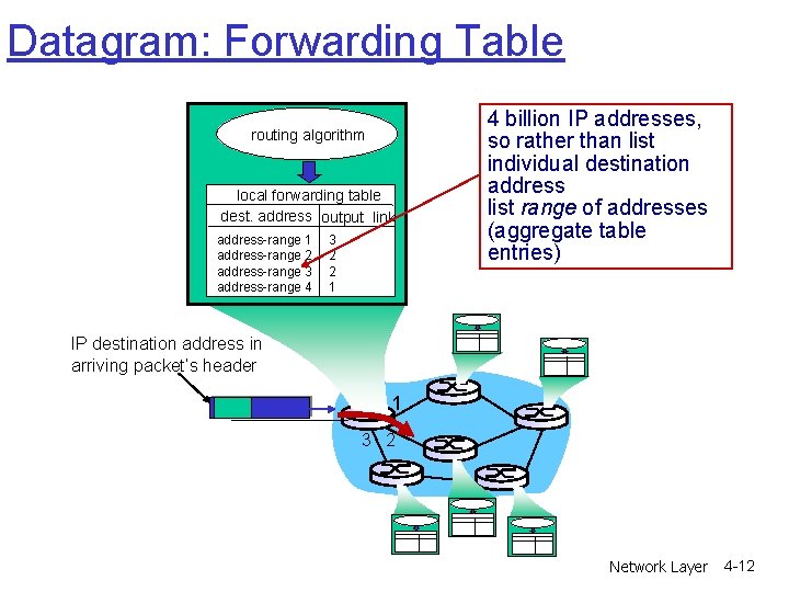
Datagram: Forwarding Table routing algorithm local forwarding table dest. address output link address-range 1 address-range 2 address-range 3 address-range 4 3 2 2 1 4 billion IP addresses, so rather than list individual destination address list range of addresses (aggregate table entries) IP destination address in arriving packet’s header 1 3 2 Network Layer 4 -12
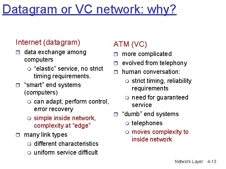
Datagram or VC network: why? Internet (datagram) ATM (VC) r data exchange among r more complicated computers r evolved from telephony m “elastic” service, no strict r human conversation: timing requirements. m strict timing, reliability r “smart” end systems requirements (computers) m need for guaranteed m can adapt, perform control, service error recovery r “dumb” end systems m simple inside network, m telephones complexity at “edge” m moves complexity to r many link types inside network m different characteristics m uniform service difficult Network Layer 4 -13
Chapter 4: Network Layer r 4. 1 Introduction r 4. 2 Virtual circuit and datagram networks r 4. 3 What’s inside a router r 4. 4 IP: Internet Protocol m m Datagram format IPv 4 addressing ICMP IPv 6 r 4. 5 Routing algorithms m Link state m Distance Vector m Hierarchical routing r 4. 6 Routing in the Internet m m m RIP OSPF BGP r 4. 7 Broadcast and multicast routing Network Layer 4 -14
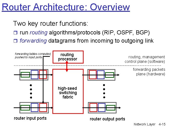
Router Architecture: Overview Two key router functions: r run routing algorithms/protocols (RIP, OSPF, BGP) r forwarding datagrams from incoming to outgoing link forwarding tables computed, pushed to input ports routing processor routing, management control plane (software) forwarding packets plane (hardware) high-seed switching fabric router input ports router output ports Network Layer 4 -15
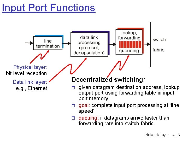
Input Port Functions Physical layer: bit-level reception Data link layer: e. g. , Ethernet Decentralized switching: r given datagram destination address, lookup output port using forwarding table in input port memory r goal: complete input port processing at ‘line speed’ r queuing: if datagrams arrive faster than forwarding rate into switch fabric Network Layer 4 -16
Three types of switching fabrics v transfer packet from input buffer to appropriate output buffer v switching rate: rate at which packets can be transferred from inputs to outputs § § often measured as multiple of input/output line rates N inputs: switching rate N times line rate is desirable Network Layer 4 -17
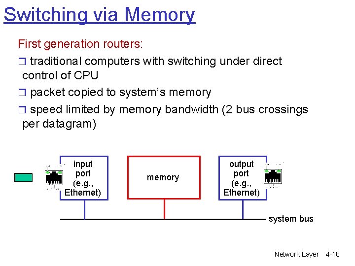
Switching via Memory First generation routers: r traditional computers with switching under direct control of CPU r packet copied to system’s memory r speed limited by memory bandwidth (2 bus crossings per datagram) input port (e. g. , Ethernet) memory output port (e. g. , Ethernet) system bus Network Layer 4 -18
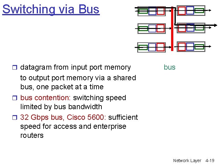
Switching via Bus r datagram from input port memory bus to output port memory via a shared bus, one packet at a time r bus contention: switching speed limited by bus bandwidth r 32 Gbps bus, Cisco 5600: sufficient speed for access and enterprise routers Network Layer 4 -19
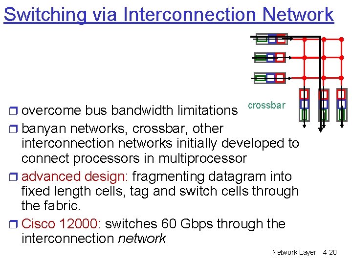
Switching via Interconnection Network r overcome bus bandwidth limitations crossbar r banyan networks, crossbar, other interconnection networks initially developed to connect processors in multiprocessor r advanced design: fragmenting datagram into fixed length cells, tag and switch cells through the fabric. r Cisco 12000: switches 60 Gbps through the interconnection network Network Layer 4 -20
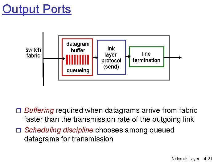
Output Ports switch fabric datagram buffer queueing link layer protocol (send) line termination r Buffering required when datagrams arrive from fabric faster than the transmission rate of the outgoing link r Scheduling discipline chooses among queued datagrams for transmission Network Layer 4 -21
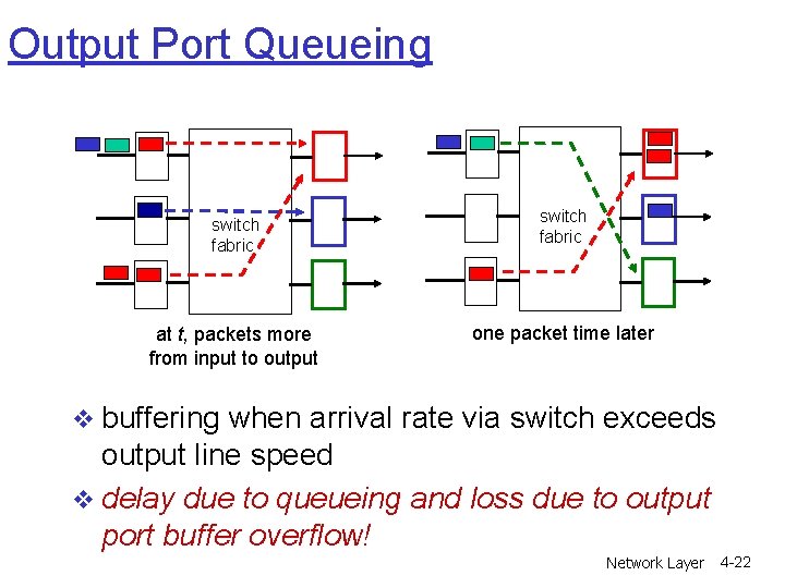
Output Port Queueing switch fabric at t, packets more from input to output switch fabric one packet time later v buffering when arrival rate via switch exceeds output line speed v delay due to queueing and loss due to output port buffer overflow! Network Layer 4 -22
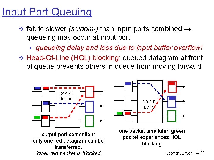
Input Port Queuing v fabric slower (seldom!) than input ports combined → queueing may occur at input port § queueing delay and loss due to input buffer overflow! v Head-Of-Line (HOL) blocking: queued datagram at front of queue prevents others in queue from moving forward switch fabric output port contention: only one red datagram can be transferred. lower red packet is blocked switch fabric one packet time later: green packet experiences HOL blocking Network Layer 4 -23
Chapter 4: Network Layer r 4. 1 Introduction r 4. 2 Virtual circuit and datagram networks r 4. 3 What’s inside a router r 4. 4 IP: Internet Protocol m m Datagram format IPv 4 addressing ICMP IPv 6 r 4. 5 Routing algorithms m Link state m Distance Vector m Hierarchical routing r 4. 6 Routing in the Internet m m m RIP OSPF BGP r 4. 7 Broadcast and multicast routing Network Layer 4 -24
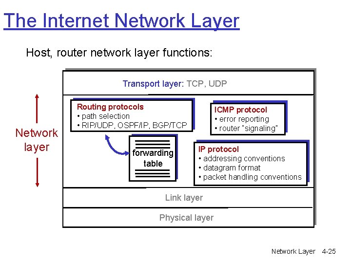
The Internet Network Layer Host, router network layer functions: Transport layer: TCP, UDP Network layer Routing protocols • path selection • RIP/UDP, OSPF/IP, BGP/TCP forwarding table ICMP protocol • error reporting • router “signaling” IP protocol • addressing conventions • datagram format • packet handling conventions Link layer Physical layer Network Layer 4 -25
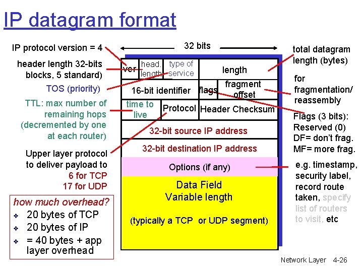
IP datagram format 32 bits IP protocol version = 4 header length 32 -bits blocks, 5 standard) TOS (priority) TTL: max number of remaining hops (decremented by one at each router) Upper layer protocol to deliver payload to 6 for TCP 17 for UDP how much overhead? v 20 bytes of TCP v 20 bytes of IP v = 40 bytes + app layer overhead ver head. type of length service length fragment 16 -bit identifier flags offset time to Protocol Header Checksum live 32 -bit source IP address 32 -bit destination IP address Options (if any) Data Field Variable length (typically a TCP or UDP segment) total datagram length (bytes) for fragmentation/ reassembly Flags (3 bits): Reserved (0) DF= don’t frag. MF= more frag. e. g. timestamp, security label, record route taken, specify list of routers to visit, etc Network Layer 4 -26
Chapter 4: Network Layer r 4. 1 Introduction r 4. 2 Virtual circuit and datagram networks r 4. 3 What’s inside a router r 4. 4 IP: Internet Protocol m m Datagram format IPv 4 addressing ICMP IPv 6 r 4. 5 Routing algorithms m Link state m Distance Vector m Hierarchical routing r 4. 6 Routing in the Internet m m m RIP OSPF BGP r 4. 7 Broadcast and multicast routing Network Layer 4 -27
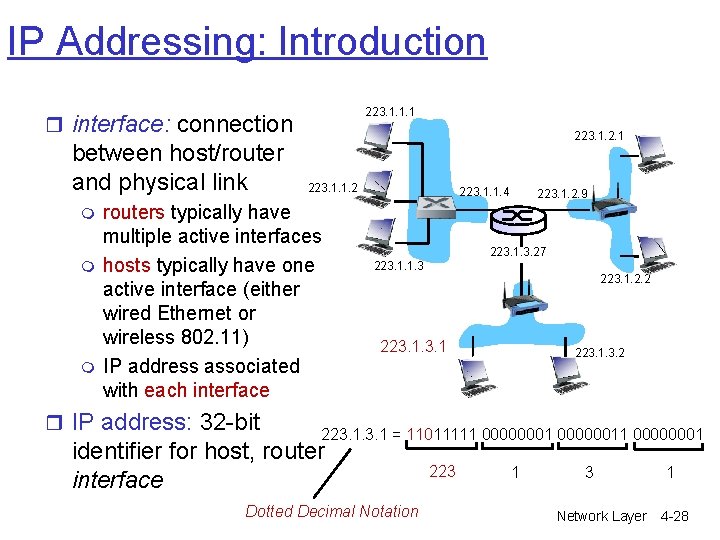
IP Addressing: Introduction 223. 1. 1. 1 r interface: connection between host/router and physical link m m m 223. 1. 2. 1 223. 1. 1. 2 routers typically have multiple active interfaces hosts typically have one active interface (either wired Ethernet or wireless 802. 11) IP address associated with each interface r IP address: 32 -bit 223. 1. 1. 4 223. 1. 2. 9 223. 1. 3. 27 223. 1. 1. 3 223. 1. 2. 2 223. 1. 3. 2 223. 1 = 11011111 000000011 00000001 identifier for host, router interface Dotted Decimal Notation 223 1 3 Network Layer 1 4 -28
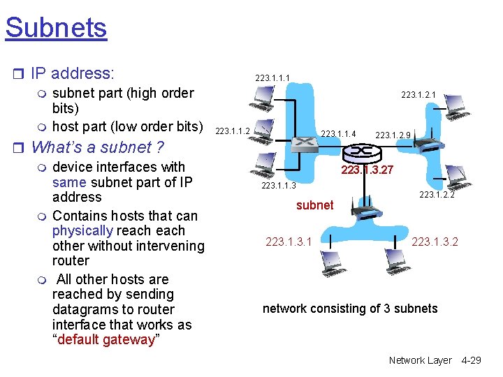
Subnets r IP address: m subnet part (high order bits) m host part (low order bits) r What’s a subnet ? m device interfaces with same subnet part of IP address m Contains hosts that can physically reach other without intervening router m All other hosts are reached by sending datagrams to router interface that works as “default gateway” 223. 1. 1. 1 223. 1. 2. 1 223. 1. 1. 2 223. 1. 1. 4 223. 1. 2. 9 223. 1. 3. 27 223. 1. 1. 3 subnet 223. 1. 2. 2 223. 1. 3. 2 network consisting of 3 subnets Network Layer 4 -29
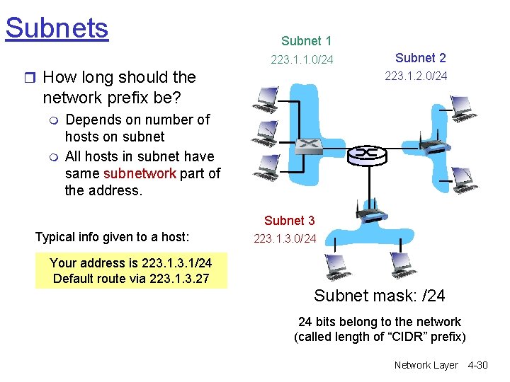
Subnets Subnet 1 223. 1. 1. 0/24 r How long should the Subnet 2 223. 1. 2. 0/24 network prefix be? m m Depends on number of hosts on subnet All hosts in subnet have same subnetwork part of the address. Subnet 3 Typical info given to a host: 223. 1. 3. 0/24 Your address is 223. 1/24 Default route via 223. 1. 3. 27 Subnet mask: /24 24 bits belong to the network (called length of “CIDR” prefix) Network Layer 4 -30
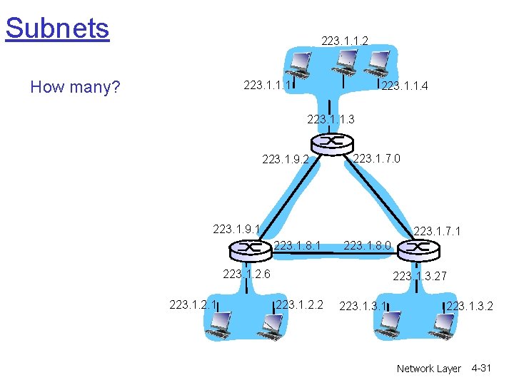
Subnets 223. 1. 1. 2 How many? 223. 1. 1. 1 223. 1. 1. 4 223. 1. 1. 3 223. 1. 9. 2 223. 1. 7. 0 223. 1. 9. 1 223. 1. 7. 1 223. 1. 8. 0 223. 1. 2. 6 223. 1. 2. 1 223. 1. 3. 27 223. 1. 2. 2 223. 1. 3. 2 Network Layer 4 -31
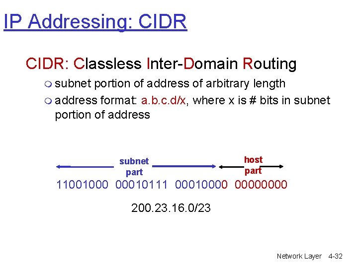
IP Addressing: CIDR: Classless Inter-Domain Routing m subnet portion of address of arbitrary length m address format: a. b. c. d/x, where x is # bits in subnet portion of address subnet part host part 11001000 00010111 00010000 200. 23. 16. 0/23 Network Layer 4 -32
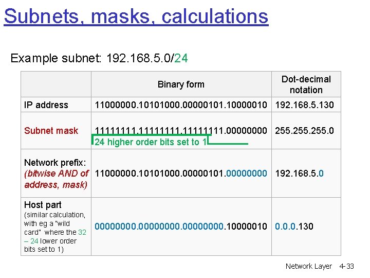
Subnets, masks, calculations Example subnet: 192. 168. 5. 0/24 Binary form Dot-decimal notation IP address 11000000. 10101000. 00000101. 10000010 192. 168. 5. 130 Subnet mask 11111111. 0000 255. 0 24 higher order bits set to 1 Network prefix: (bitwise AND of 11000000. 10101000. 00000101. 0000 192. 168. 5. 0 address, mask) Host part (similar calculation, with eg a ”wild card” where the 32 – 24 lower order bits set to 1) 00000000. 10000010 0. 0. 0. 130 Network Layer 4 -33
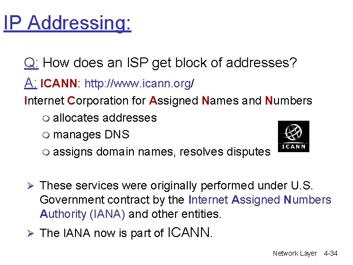
IP Addressing: Q: How does an ISP get block of addresses? A: ICANN: http: //www. icann. org/ Internet Corporation for Assigned Names and Numbers m allocates addresses m manages DNS m assigns domain names, resolves disputes Ø These services were originally performed under U. S. Government contract by the Internet Assigned Numbers Authority (IANA) and other entities. Ø The IANA now is part of ICANN. Network Layer 4 -34
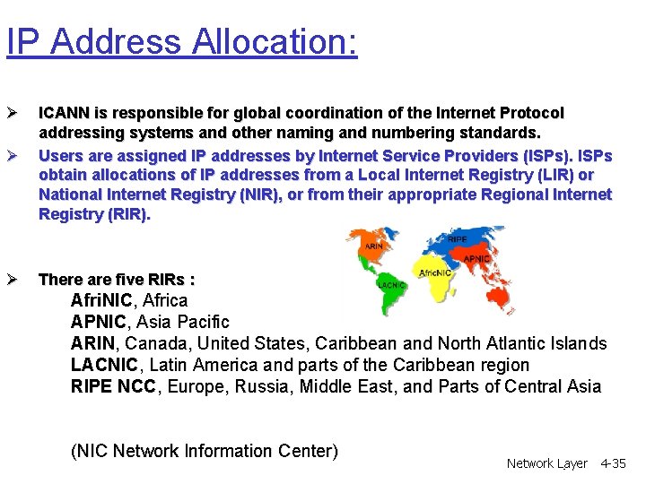
IP Address Allocation: Ø Ø ICANN is responsible for global coordination of the Internet Protocol addressing systems and other naming and numbering standards. Users are assigned IP addresses by Internet Service Providers (ISPs). ISPs obtain allocations of IP addresses from a Local Internet Registry (LIR) or National Internet Registry (NIR), or from their appropriate Regional Internet Registry (RIR). Ø There are five RIRs : Afri. NIC, Africa APNIC, Asia Pacific ARIN, Canada, United States, Caribbean and North Atlantic Islands LACNIC, Latin America and parts of the Caribbean region RIPE NCC, Europe, Russia, Middle East, and Parts of Central Asia (NIC Network Information Center) Network. Layer 4 -35
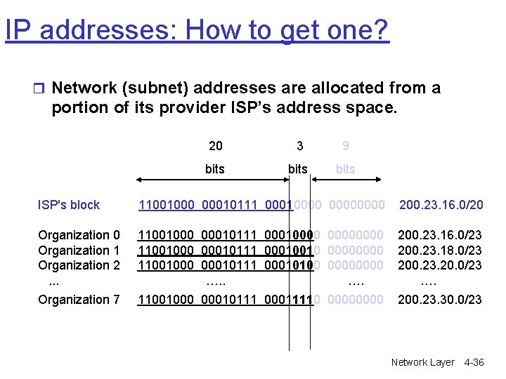
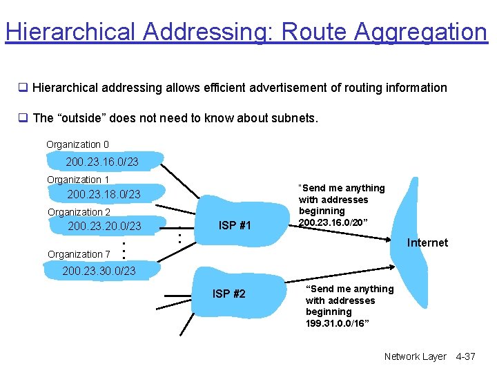
IP addresses: How to get one? r Network (subnet) addresses are allocated from a portion of its provider ISP’s address space. 20 3 9 bits ISP's block 11001000 00010111 00010000 200. 23. 16. 0/20 Organization 1 Organization 2. . . 11001000 00010111 00010000 11001000 00010111 00010010 0000 11001000 00010111 00010100 0000 …. 200. 23. 16. 0/23 200. 23. 18. 0/23 200. 23. 20. 0/23 …. Organization 7 11001000 00010111 00011110 0000 200. 23. 30. 0/23 Network Layer 4 -36
Hierarchical Addressing: Route Aggregation q Hierarchical addressing allows efficient advertisement of routing information q The “outside” does not need to know about subnets. Organization 0 200. 23. 16. 0/23 Organization 1 200. 23. 18. 0/23 Organization 2 200. 23. 20. 0/23 Organization 7 . . . ISP #1 “Send me anything with addresses beginning 200. 23. 16. 0/20” Internet 200. 23. 30. 0/23 ISP #2 “Send me anything with addresses beginning 199. 31. 0. 0/16” Network Layer 4 -37
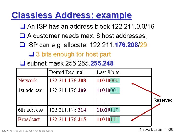
Classless Address: example q An ISP has an address block 122. 211. 0. 0/16 q A customer needs max. 6 host addresses, q ISP can e. g. allocate: 122. 211. 176. 208/29 q 3 bits enough for host part q subnet mask 255. 248 Dotted Decimal Last 8 bits Network 122. 211. 176. 208 11010000 1 st address 122. 211. 176. 209 11010001 ………………… 6 th address 122. 211. 176. 214 11010110 Broadcast 122. 211. 176. 215 11010111 2013 Ali Salehson, Chalmers, CSE Networks and Systems Reserved Network Layer 4 -38
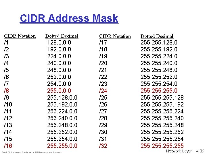
CIDR Address Mask CIDR Notation /1 /2 /3 /4 /5 /6 /7 /8 /9 /10 /11 /12 /13 /14 /15 /16 Dotted Decimal 128. 0. 0. 0 192. 0. 0. 0 224. 0. 0. 0 240. 0 248. 0. 0. 0 252. 0. 0. 0 254. 0. 0. 0 255. 128. 0. 0 255. 192. 0. 0 255. 224. 0. 0 255. 240. 0. 0 255. 248. 0. 0 255. 252. 0. 0 255. 254. 0. 0 255. 0. 0 2013 Ali Salehson, Chalmers, CSE Networks and Systems CIDR Notation Dotted Decimal /17 /18 /19 /20 /21 /22 /23 /24 /25 /26 /27 /28 /29 /30 /31 /32 255. 128. 0 255. 192. 0 255. 224. 0 255. 240. 0 255. 248. 0 255. 252. 0 255. 254. 0 255. 128 255. 192 255. 224 255. 240 255. 248 255. 252 255. 254 255 Network Layer 4 -39
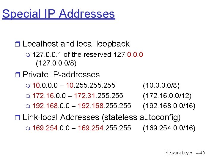
Special IP Addresses r Localhost and local loopback m 127. 0. 0. 1 of the reserved 127. 0. 0. 0 (127. 0. 0. 0/8) r Private IP-addresses m 10. 0 – 10. 255 m 172. 16. 0. 0 – 172. 31. 255 m 192. 168. 0. 0 – 192. 168. 255 (10. 0/8) (172. 16. 0. 0/12) (192. 168. 0. 0/16) r Link-local Addresses (stateless autoconfig) m 169. 254. 0. 0 – 169. 254. 255 (169. 254. 0. 0/16) Network Layer 4 -40
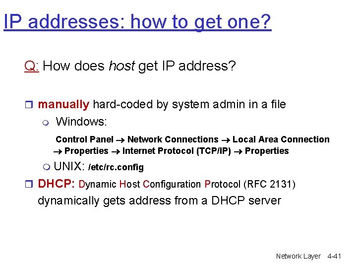
IP addresses: how to get one? Q: How does host get IP address? r manually hard-coded by system admin in a file m Windows: Control Panel Network Connections Local Area Connection Properties Internet Protocol (TCP/IP) Properties m UNIX: /etc/rc. config r DHCP: Dynamic Host Configuration Protocol (RFC 2131) dynamically gets address from a DHCP server Network Layer 4 -41
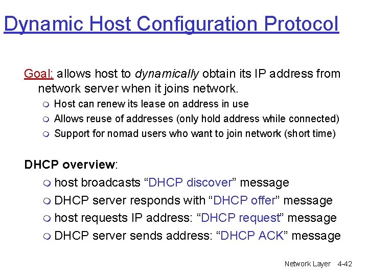
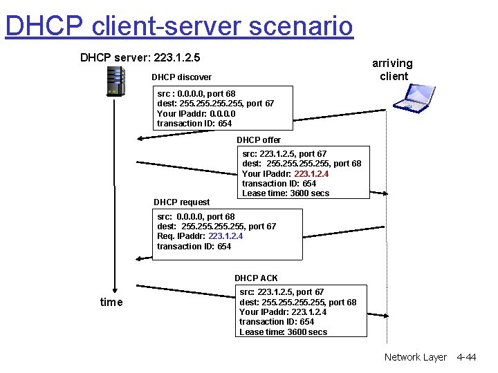
Dynamic Host Configuration Protocol Goal: allows host to dynamically obtain its IP address from network server when it joins network. m m m Host can renew its lease on address in use Allows reuse of addresses (only hold address while connected) Support for nomad users who want to join network (short time) DHCP overview: m host broadcasts “DHCP discover” message m DHCP server responds with “DHCP offer” message m host requests IP address: “DHCP request” message m DHCP server sends address: “DHCP ACK” message Network Layer 4 -42
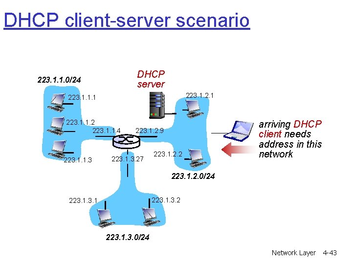
DHCP client-server scenario DHCP server 223. 1. 1. 0/24 223. 1. 2. 1 223. 1. 1. 2 223. 1. 1. 4 223. 1. 1. 3 223. 1. 2. 9 223. 1. 3. 27 223. 1. 2. 2 arriving DHCP client needs address in this network 223. 1. 2. 0/24 223. 1. 3. 2 223. 1. 3. 0/24 Network Layer 4 -43
DHCP client-server scenario DHCP server: 223. 1. 2. 5 arriving client DHCP discover src : 0. 0, port 68 dest: 255, port 67 Your IPaddr: 0. 0 transaction ID: 654 DHCP offer DHCP request src: 223. 1. 2. 5, port 67 dest: 255, port 68 Your IPaddr: 223. 1. 2. 4 transaction ID: 654 Lease time: 3600 secs src: 0. 0, port 68 dest: 255, port 67 Req. IPaddr: 223. 1. 2. 4 transaction ID: 654 DHCP ACK time src: 223. 1. 2. 5, port 67 dest: 255, port 68 Your IPaddr: 223. 1. 2. 4 transaction ID: 654 Lease time: 3600 secs Network Layer 4 -44
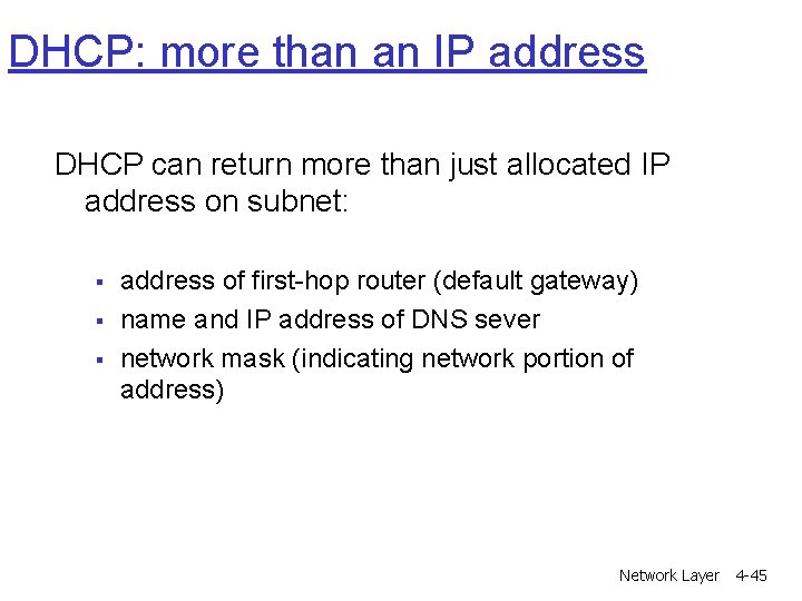
DHCP: more than an IP address DHCP can return more than just allocated IP address on subnet: § § § address of first-hop router (default gateway) name and IP address of DNS sever network mask (indicating network portion of address) Network Layer 4 -45
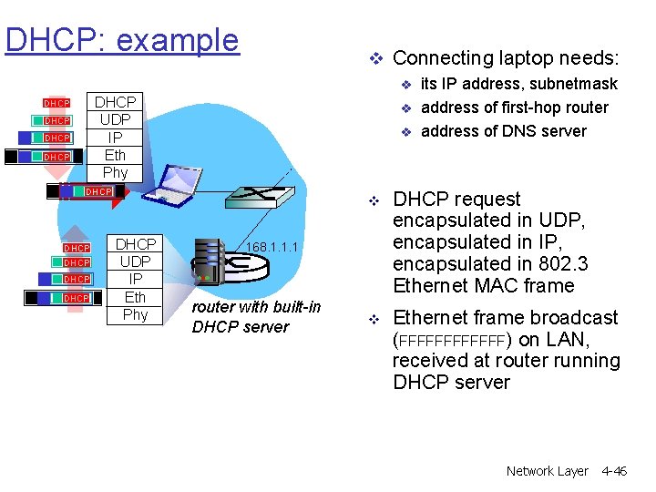
DHCP: example v Connecting laptop needs: v DHCP UDP IP Eth Phy DHCP v v DHCP DHCP UDP IP Eth Phy v DHCP request encapsulated in UDP, encapsulated in IP, encapsulated in 802. 3 Ethernet MAC frame v Ethernet frame broadcast (FFFFFF) on LAN, received at router running DHCP server 168. 1. 1. 1 router with built-in DHCP server its IP address, subnetmask address of first-hop router address of DNS server Network Layer 4 -46
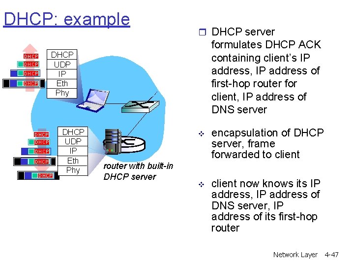
DHCP: example r DHCP server formulates DHCP ACK containing client’s IP address, IP address of first-hop router for client, IP address of DNS server DHCP UDP IP Eth Phy DHCP DHCP DHCP UDP IP Eth Phy router with built-in DHCP server v encapsulation of DHCP server, frame forwarded to client v client now knows its IP address, IP address of DNS server, IP address of its first-hop router Network Layer 4 -47
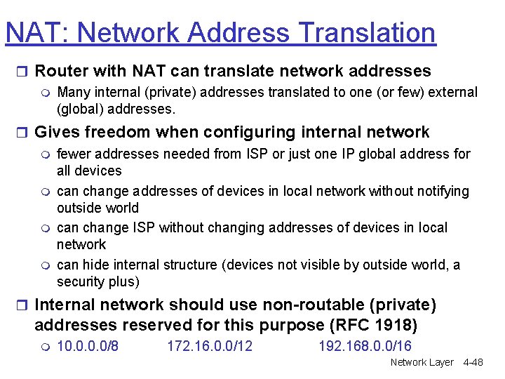
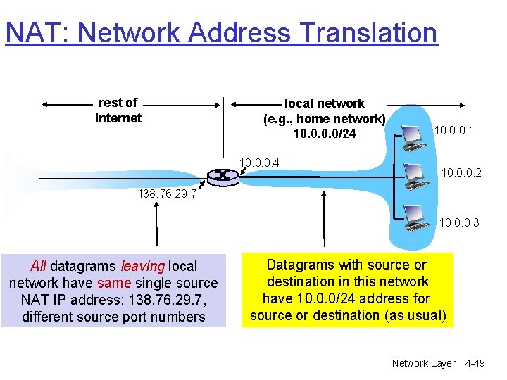
NAT: Network Address Translation r Router with NAT can translate network addresses m Many internal (private) addresses translated to one (or few) external (global) addresses. r Gives freedom when configuring internal network m fewer addresses needed from ISP or just one IP global address for all devices m can change addresses of devices in local network without notifying outside world m can change ISP without changing addresses of devices in local network m can hide internal structure (devices not visible by outside world, a security plus) r Internal network should use non-routable (private) addresses reserved for this purpose (RFC 1918) m 10. 0/8 172. 16. 0. 0/12 192. 168. 0. 0/16 Network Layer 4 -48
NAT: Network Address Translation rest of Internet local network (e. g. , home network) 10. 0/24 10. 0. 0. 1 10. 0. 0. 2 138. 76. 29. 7 10. 0. 0. 3 All datagrams leaving local network have same single source NAT IP address: 138. 76. 29. 7, different source port numbers Datagrams with source or destination in this network have 10. 0. 0/24 address for source or destination (as usual) Network Layer 4 -49
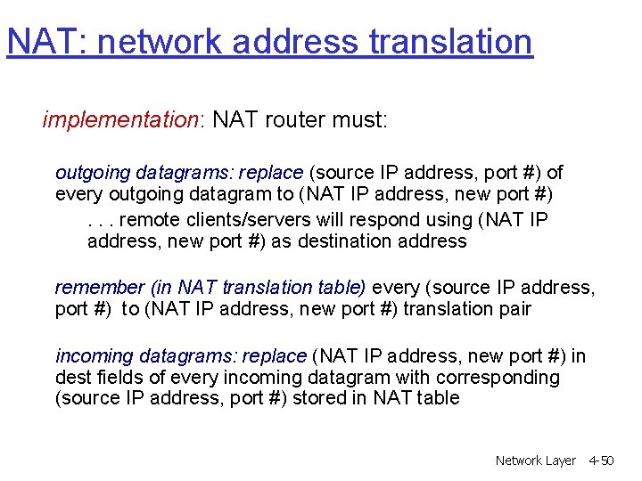
NAT: network address translation implementation: NAT router must: outgoing datagrams: replace (source IP address, port #) of every outgoing datagram to (NAT IP address, new port #). . . remote clients/servers will respond using (NAT IP address, new port #) as destination address remember (in NAT translation table) every (source IP address, port #) to (NAT IP address, new port #) translation pair incoming datagrams: replace (NAT IP address, new port #) in dest fields of every incoming datagram with corresponding (source IP address, port #) stored in NAT table Network Layer 4 -50
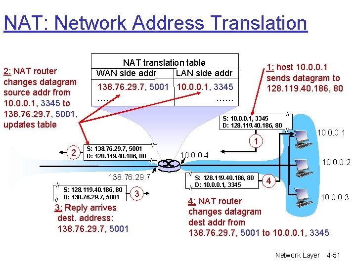
NAT: Network Address Translation 2: NAT router changes datagram source addr from 10. 0. 0. 1, 3345 to 138. 76. 29. 7, 5001, updates table 2 NAT translation table WAN side addr LAN side addr 1: host 10. 0. 0. 1 sends datagram to 128. 119. 40. 186, 80 138. 76. 29. 7, 5001 10. 0. 0. 1, 3345 …… …… S: 10. 0. 0. 1, 3345 D: 128. 119. 40. 186, 80 S: 138. 76. 29. 7, 5001 D: 128. 119. 40. 186, 80 138. 76. 29. 7 S: 128. 119. 40. 186, 80 D: 138. 76. 29. 7, 5001 3: Reply arrives dest. address: 138. 76. 29. 7, 5001 3 1 10. 0. 0. 4 S: 128. 119. 40. 186, 80 D: 10. 0. 0. 1, 3345 10. 0. 0. 2 4 10. 0. 0. 3 4: NAT router changes datagram dest addr from 138. 76. 29. 7, 5001 to 10. 0. 0. 1, 3345 Network Layer 4 -51
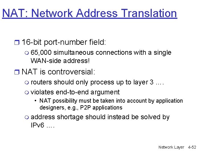
NAT: Network Address Translation r 16 -bit port-number field: m 65, 000 simultaneous connections with a single WAN-side address! r NAT is controversial: m routers should only process up to layer 3 …. m violates end-to-end argument • NAT possibility must be taken into account by application designers, e. g. , P 2 P applications m address shortage should instead be solved by IPv 6 …. Network Layer 4 -52
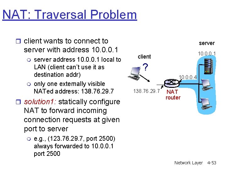
NAT: Traversal Problem r client wants to connect to server with address 10. 0. 0. 1 m m server address 10. 0. 0. 1 local to LAN (client can’t use it as destination addr) only one externally visible NATed address: 138. 76. 29. 7 r solution 1: statically configure server 10. 0. 0. 1 client ? 10. 0. 0. 4 138. 76. 29. 7 NAT router NAT to forward incoming connection requests at given port to server m e. g. , (123. 76. 29. 7, port 2500) always forwarded to 10. 0. 0. 1 port 2500 Network Layer 4 -53
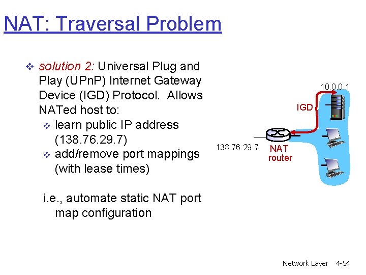
NAT: Traversal Problem v solution 2: Universal Plug and Play (UPn. P) Internet Gateway Device (IGD) Protocol. Allows NATed host to: v learn public IP address (138. 76. 29. 7) v add/remove port mappings (with lease times) 10. 0. 0. 1 IGD 138. 76. 29. 7 NAT router i. e. , automate static NAT port map configuration Network Layer 4 -54
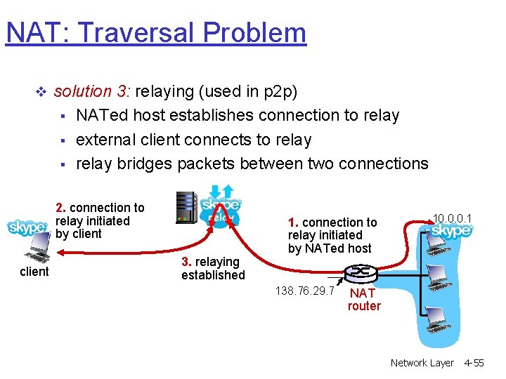
NAT: Traversal Problem v solution 3: relaying (used in p 2 p) § § § NATed host establishes connection to relay external client connects to relay bridges packets between two connections 2. connection to relay initiated by client 3. relaying established 1. connection to relay initiated by NATed host 138. 76. 29. 7 10. 0. 0. 1 NAT router Network Layer 4 -55
Chapter 4: Network Layer r 4. 1 Introduction r 4. 2 Virtual circuit and datagram networks r 4. 3 What’s inside a router r 4. 4 IP: Internet Protocol m m Datagram format IPv 4 addressing ICMP IPv 6 r 4. 5 Routing algorithms m Link state m Distance Vector m Hierarchical routing r 4. 6 Routing in the Internet m m m RIP OSPF BGP r 4. 7 Broadcast and multicast routing Network Layer 4 -56
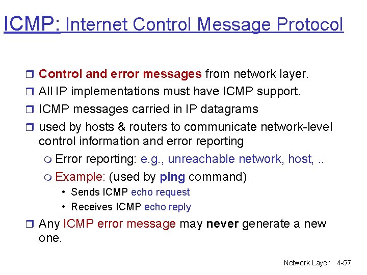
ICMP: Internet Control Message Protocol r Control and error messages from network layer. r All IP implementations must have ICMP support. r ICMP messages carried in IP datagrams r used by hosts & routers to communicate network-level control information and error reporting m Error reporting: e. g. , unreachable network, host, . . m Example: (used by ping command) • Sends ICMP echo request • Receives ICMP echo reply r Any ICMP error message may never generate a new one. Network Layer 4 -57
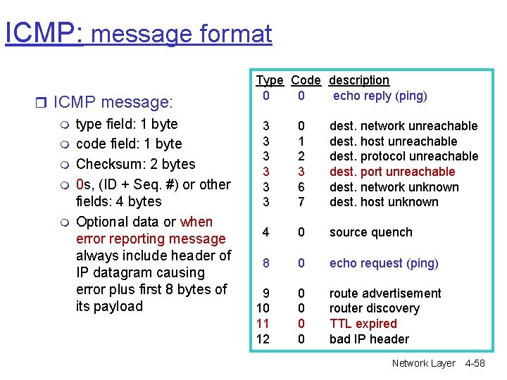
ICMP: message format r ICMP message: m type field: 1 byte m code field: 1 byte m Checksum: 2 bytes m 0 s, (ID + Seq. #) or other fields: 4 bytes m Optional data or when error reporting message always include header of IP datagram causing error plus first 8 bytes of its payload Type Code description 0 0 echo reply (ping) 3 3 3 0 1 2 3 6 7 dest. network unreachable dest. host unreachable dest. protocol unreachable dest. port unreachable dest. network unknown dest. host unknown 4 0 source quench 8 0 echo request (ping) 9 10 11 12 0 0 route advertisement router discovery TTL expired bad IP header Network Layer 4 -58
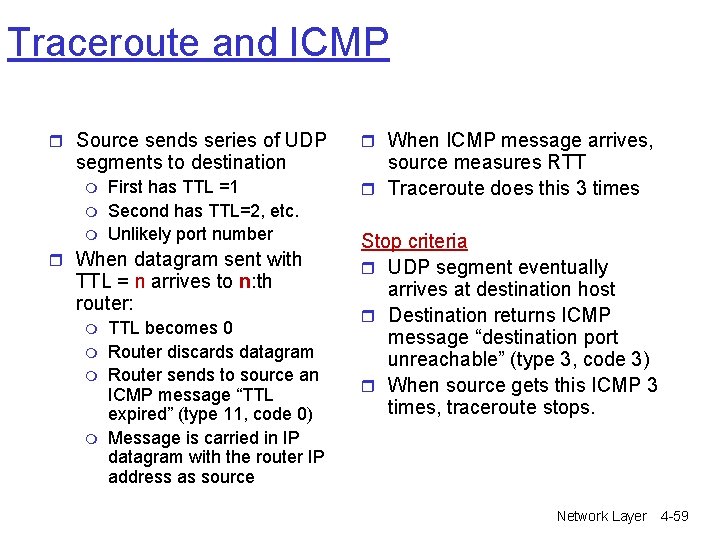
Traceroute and ICMP r Source sends series of UDP segments to destination m m m First has TTL =1 Second has TTL=2, etc. Unlikely port number r When datagram sent with TTL = n arrives to n: th router: m m TTL becomes 0 Router discards datagram Router sends to source an ICMP message “TTL expired” (type 11, code 0) Message is carried in IP datagram with the router IP address as source r When ICMP message arrives, source measures RTT r Traceroute does this 3 times Stop criteria r UDP segment eventually arrives at destination host r Destination returns ICMP message “destination port unreachable” (type 3, code 3) r When source gets this ICMP 3 times, traceroute stops. Network Layer 4 -59
Chapter 4: Network Layer r 4. 1 Introduction r 4. 2 Virtual circuit and datagram networks r 4. 3 What’s inside a router r 4. 4 IP: Internet Protocol m m Datagram format IPv 4 addressing ICMP IPv 6 r 4. 5 Routing algorithms m Link state m Distance Vector m Hierarchical routing r 4. 6 Routing in the Internet m m m RIP OSPF BGP r 4. 7 Broadcast and multicast routing Network Layer 4 -60
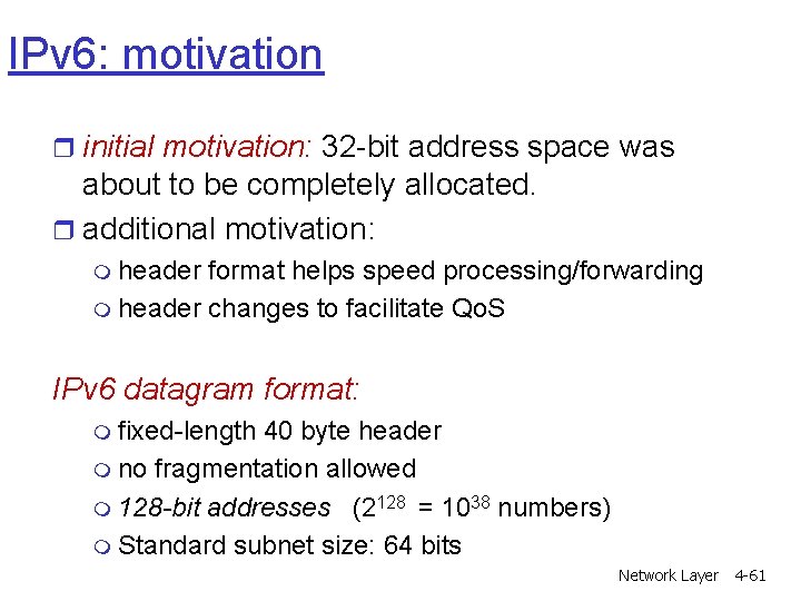
IPv 6: motivation r initial motivation: 32 -bit address space was about to be completely allocated. r additional motivation: m header format helps speed processing/forwarding m header changes to facilitate Qo. S IPv 6 datagram format: m fixed-length 40 byte header m no fragmentation allowed m 128 -bit addresses (2128 = 1038 numbers) m Standard subnet size: 64 bits Network Layer 4 -61
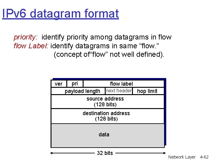
IPv 6 datagram format priority: identify priority among datagrams in flow Label: identify datagrams in same “flow. ” (concept of“flow” not well defined). ver pri flow label payload length next header hop limit source address (128 bits) destination address (128 bits) data 32 bits Network Layer 4 -62
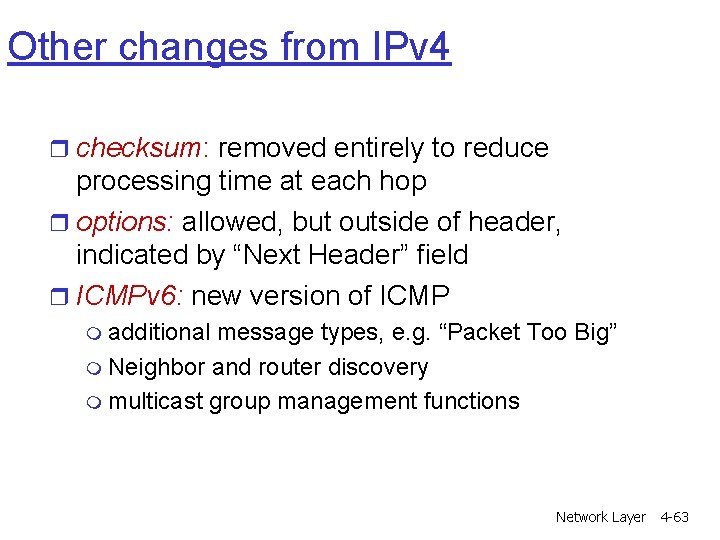
Other changes from IPv 4 r checksum: removed entirely to reduce processing time at each hop r options: allowed, but outside of header, indicated by “Next Header” field r ICMPv 6: new version of ICMP m additional message types, e. g. “Packet Too Big” m Neighbor and router discovery m multicast group management functions Network Layer 4 -63
More slides r IPv 4 Fragmentation r Datagram Forwarding Table r Getting a datagram from source to destination r IPv 6 -IPv 4 Tunneling Network Layer 4 -64
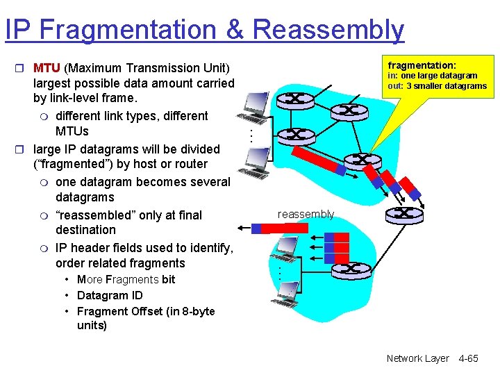
IP Fragmentation & Reassembly fragmentation: r MTU (Maximum Transmission Unit) reassembly … • More Fragments bit • Datagram ID • Fragment Offset (in 8 -byte units) in: one large datagram out: 3 smaller datagrams … largest possible data amount carried by link-level frame. m different link types, different MTUs r large IP datagrams will be divided (“fragmented”) by host or router m one datagram becomes several datagrams m “reassembled” only at final destination m IP header fields used to identify, order related fragments Network Layer 4 -65
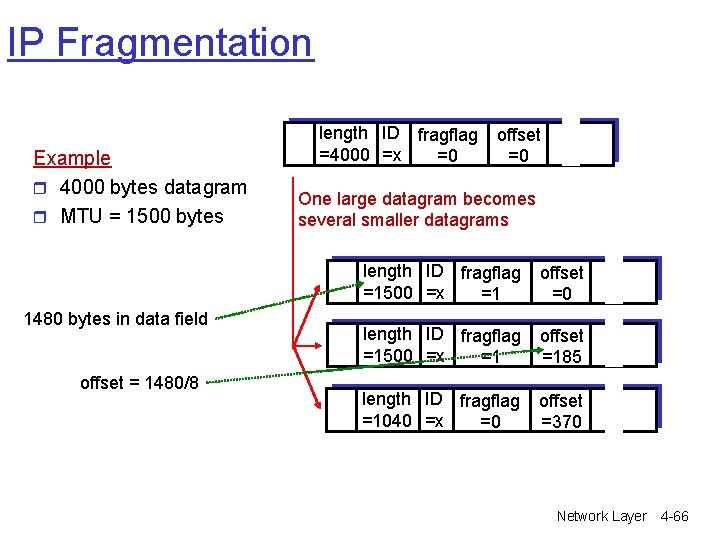
IP Fragmentation Example r 4000 bytes datagram r MTU = 1500 bytes 1480 bytes in data field offset = 1480/8 length ID fragflag =4000 =x =0 offset =0 One large datagram becomes several smaller datagrams length ID fragflag =1500 =x =1 offset =0 length ID fragflag =1500 =x =1 offset =185 length ID fragflag =1040 =x =0 offset =370 Network Layer 4 -66
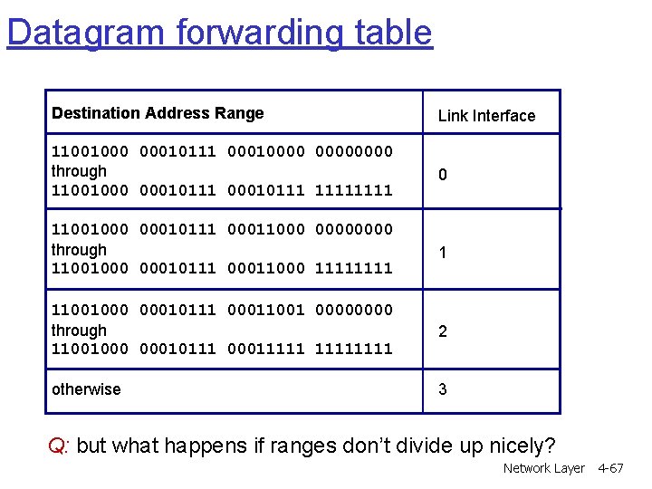
Datagram forwarding table Destination Address Range Link Interface 11001000 00010111 00010000 through 11001000 00010111 1111 0 11001000 00010111 00011000 0000 through 11001000 00010111 00011000 1111 1 11001000 00010111 00011001 0000 through 11001000 00010111 00011111 2 otherwise 3 Q: but what happens if ranges don’t divide up nicely? Network Layer 4 -67
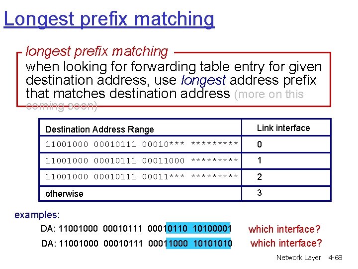
Longest prefix matching longest prefix matching when looking forwarding table entry for given destination address, use longest address prefix that matches destination address (more on this coming soon) Destination Address Range Link interface 11001000 00010111 00010*** ***** 0 11001000 00010111 00011000 ***** 1 11001000 00010111 00011*** ***** 2 otherwise 3 examples: DA: 11001000 00010111 00010110 10100001 DA: 11001000 00010111 00011000 1010 which interface? Network Layer 4 -68
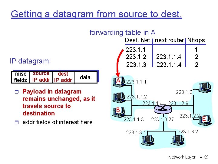
Getting a datagram from source to dest. forwarding table in A Dest. Net. next router Nhops 223. 1. 1 223. 1. 2 223. 1. 3 IP datagram: misc source dest fields IP addr data A r Payload in datagram remains unchanged, as it travels source to destination r addr fields of interest here 223. 1. 1. 4 1 2 2 223. 1. 1. 1 223. 1. 1. 2 223. 1. 1. 4 223. 1. 2. 1 223. 1. 2. 9 B 223. 1. 1. 3 223. 1. 3. 27 223. 1. 2. 2 E 223. 1. 3. 2 Network Layer 4 -69
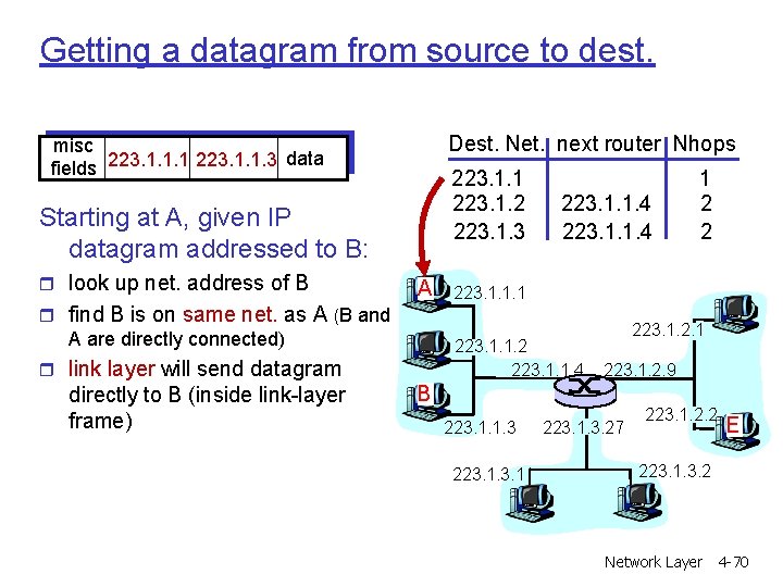
Getting a datagram from source to dest. Dest. Net. next router Nhops misc data fields 223. 1. 1. 1 223. 1. 1. 3 223. 1. 1 223. 1. 2 223. 1. 3 Starting at A, given IP datagram addressed to B: r look up net. address of B A r find B is on same net. as A (B and A are directly connected) 223. 1. 1. 1 223. 1. 1. 2 223. 1. 1. 4 r link layer will send datagram directly to B (inside link-layer frame) 223. 1. 1. 4 1 2 2 223. 1. 2. 1 223. 1. 2. 9 B 223. 1. 1. 3 223. 1. 3. 27 223. 1. 2. 2 E 223. 1. 3. 2 Network Layer 4 -70
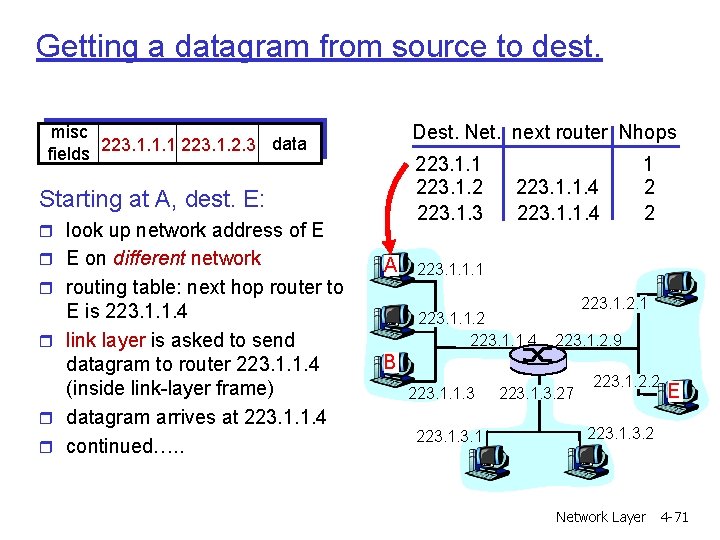
Getting a datagram from source to dest. Dest. Net. next router Nhops misc data fields 223. 1. 1. 1 223. 1. 2. 3 223. 1. 1 223. 1. 2 223. 1. 3 Starting at A, dest. E: r look up network address of E r E on different network A r routing table: next hop router to E is 223. 1. 1. 4 r link layer is asked to send datagram to router 223. 1. 1. 4 (inside link-layer frame) r datagram arrives at 223. 1. 1. 4 r continued…. . 223. 1. 1. 4 1 2 2 223. 1. 1. 1 223. 1. 1. 2 223. 1. 1. 4 223. 1. 2. 1 223. 1. 2. 9 B 223. 1. 1. 3 223. 1. 3. 27 223. 1. 2. 2 E 223. 1. 3. 2 Network Layer 4 -71
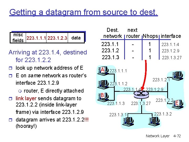
Getting a datagram from source to dest. misc data fields 223. 1. 1. 1 223. 1. 2. 3 Arriving at 223. 1. 4, destined for 223. 1. 2. 2 r look up network address of E Dest. next network router Nhops interface 223. 1. 1 223. 1. 2 223. 1. 3 A r E on same network as router’s interface 223. 1. 2. 9 m router, E directly attached r link layer sends datagram to 223. 1. 2. 2 (inside link-layer frame) via interface 223. 1. 2. 9 r datagram arrives at 223. 1. 2. 2!!! (hooray!) - 1 1 1 223. 1. 1. 4 223. 1. 2. 9 223. 1. 3. 27 223. 1. 1. 1 223. 1. 1. 2 223. 1. 1. 4 223. 1. 2. 1 223. 1. 2. 9 B 223. 1. 1. 3 223. 1. 3. 27 223. 1. 2. 2 E 223. 1. 3. 2 Network Layer 4 -72
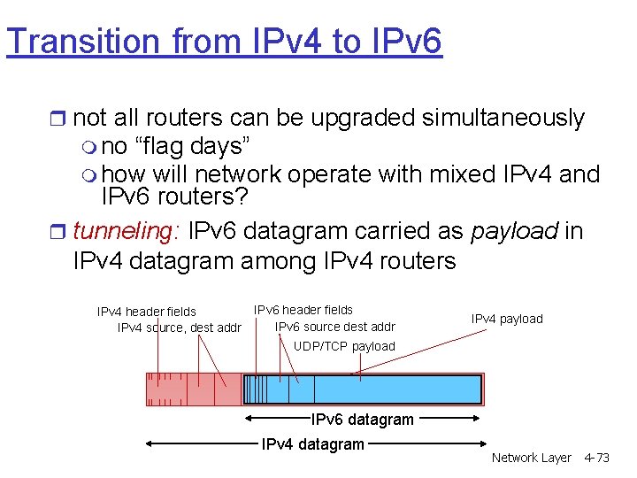
Transition from IPv 4 to IPv 6 r not all routers can be upgraded simultaneously m no “flag days” m how will network operate with mixed IPv 4 and IPv 6 routers? r tunneling: IPv 6 datagram carried as payload in IPv 4 datagram among IPv 4 routers IPv 4 header fields IPv 4 source, dest addr IPv 6 header fields IPv 6 source dest addr IPv 4 payload UDP/TCP payload IPv 6 datagram IPv 4 datagram Network Layer 4 -73
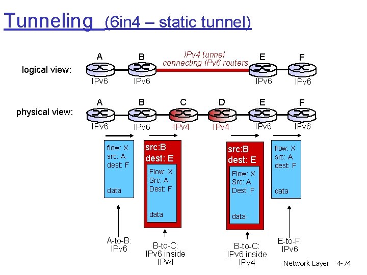
Tunneling (6 in 4 – static tunnel) IPv 4 tunnel connecting IPv 6 routers A B IPv 6 A B C IPv 6 IPv 4 logical view: physical view: flow: X src: A dest: F data A-to-B: IPv 6 E F IPv 6 D E F IPv 4 IPv 6 src: B dest: E Flow: X Src: A Dest: F data B-to-C: IPv 6 inside IPv 4 flow: X src: A dest: F data E-to-F: IPv 6 Network Layer 4 -74
Chapter 4: Network Layer r 4. 1 Introduction r 4. 2 Virtual circuit and datagram networks r 4. 3 What’s inside a router r 4. 4 IP: Internet Protocol m m Datagram format IPv 4 addressing ICMP IPv 6 r 4. 5 Routing algorithms m Link state m Distance Vector m Hierarchical routing r 4. 6 Routing in the Internet m m m RIP OSPF BGP r 4. 7 Broadcast and multicast routing Network Layer 4 -75
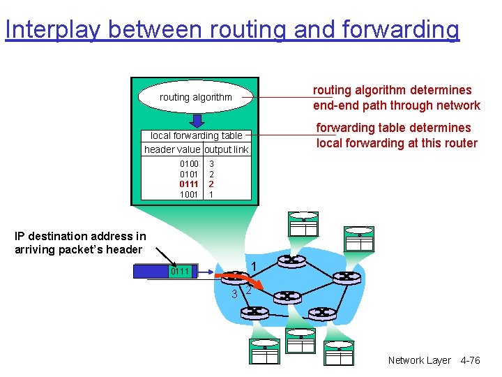
Interplay between routing and forwarding routing algorithm determines end-end path through network routing algorithm forwarding table determines local forwarding at this router local forwarding table header value output link 0100 0101 0111 1001 3 2 2 1 IP destination address in arriving packet’s header 0111 1 3 2 Network Layer 4 -76
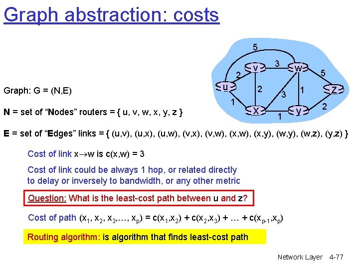
Graph abstraction: costs 5 2 Graph: G = (N, E) N = set of “Nodes” routers = { u, v, w, x, y, z } u v 2 1 x 3 w 3 1 5 z 1 y 2 E = set of “Edges” links = { (u, v), (u, x), (u, w), (v, x), (v, w), (x, y), (w, z), (y, z) } Cost of link x w is c(x, w) = 3 Cost of link could be always 1 hop, or related directly to delay or inversely to bandwidth, or any other metric Question: What is the least-cost path between u and z? Cost of path (x 1, x 2, x 3, …, xp) = c(x 1, x 2) + c(x 2, x 3) + … + c(xp-1, xp) Routing algorithm: is algorithm that finds least-cost path Network Layer 4 -77
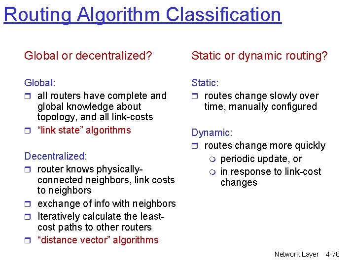
Routing Algorithm Classification Global or decentralized? Static or dynamic routing? Global: r all routers have complete and global knowledge about topology, and all link-costs r “link state” algorithms Static: r routes change slowly over time, manually configured Decentralized: r router knows physicallyconnected neighbors, link costs to neighbors r exchange of info with neighbors r Iteratively calculate the leastcost paths to other routers r “distance vector” algorithms Dynamic: r routes change more quickly m periodic update, or m in response to link-cost changes Network Layer 4 -78
Chapter 4: Network Layer r 4. 1 Introduction r 4. 2 Virtual circuit and datagram networks r 4. 3 What’s inside a router r 4. 4 IP: Internet Protocol m m Datagram format IPv 4 addressing ICMP IPv 6 r 4. 5 Routing algorithms m Link state m Distance Vector m Hierarchical routing r 4. 6 Routing in the Internet m m m RIP OSPF BGP r 4. 7 Broadcast and multicast routing Network Layer 4 -79
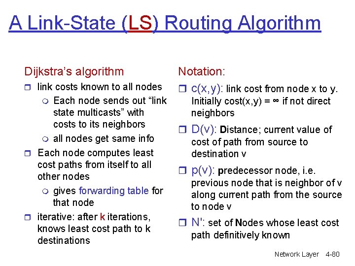
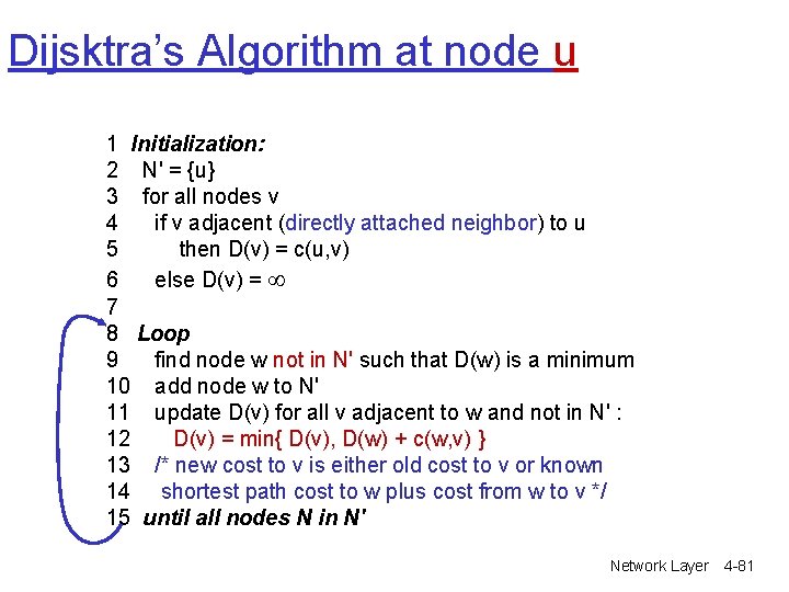
A Link-State (LS) Routing Algorithm Dijkstra’s algorithm r link costs known to all nodes Each node sends out “link state multicasts” with costs to its neighbors m all nodes get same info r Each node computes least cost paths from itself to all other nodes m gives forwarding table for that node r iterative: after k iterations, knows least cost path to k destinations m Notation: r c(x, y): link cost from node x to y. Initially cost(x, y) = ∞ if not direct neighbors r D(v): Distance; current value of cost of path from source to destination v r p(v): predecessor node, i. e. previous node that is neighbor of v along current path from the source to node v r N': set of Nodes whose least cost path definitively known Network Layer 4 -80
Dijsktra’s Algorithm at node u 1 Initialization: 2 N' = {u} 3 for all nodes v 4 if v adjacent (directly attached neighbor) to u 5 then D(v) = c(u, v) 6 else D(v) = 7 8 Loop 9 find node w not in N' such that D(w) is a minimum 10 add node w to N' 11 update D(v) for all v adjacent to w and not in N' : 12 D(v) = min{ D(v), D(w) + c(w, v) } 13 /* new cost to v is either old cost to v or known 14 shortest path cost to w plus cost from w to v */ 15 until all nodes N in N' Network Layer 4 -81
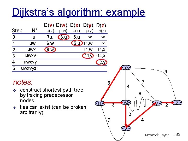
Dijkstra’s algorithm: example Step 0 1 2 3 4 5 N' u uw uwxvyz D(v) D(w) D(x) D(y) D(z) p(v) p(w) p(x) 7, u 6, w 3, u ∞ ∞ 5, u 11, w 14, x 10, v 14, x 12, y p(y) p(z) notes: v v construct shortest path tree by tracing predecessor nodes ties can exist (can be broken arbitrarily) x 5 9 7 4 8 u 3 w y 2 z 3 4 7 v Network Layer 4 -82
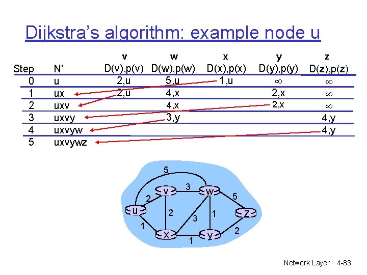
Dijkstra’s algorithm: example node u v Step 0 1 2 3 4 5 N' u ux uxvywz w D(v), p(v) D(w), p(w) 2, u 5, u 2, u 4, x 3, y x y z D(x), p(x) 1, u D(y), p(y) 2, x D(z), p(z) 4, y 2, x 5 2 u v 2 1 x 3 w 3 1 5 z 1 y 2 Network Layer 4 -83
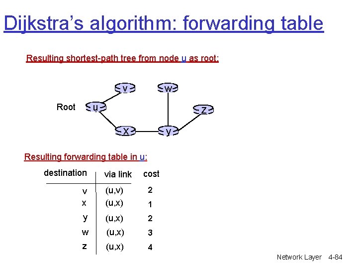
Dijkstra’s algorithm: forwarding table Resulting shortest-path tree from node u as root: v w u Root z x y Resulting forwarding table in u: destination via link cost v x (u, v) (u, x) 2 y (u, x) 2 w (u, x) 3 z (u, x) 4 1 Network Layer 4 -84
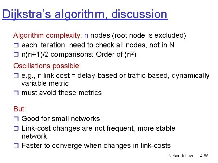
Dijkstra’s algorithm, discussion Algorithm complexity: n nodes (root node is excluded) r each iteration: need to check all nodes, not in N’ r n(n+1)/2 comparisons: Order of (n 2) Oscillations possible: r e. g. , if link cost = delay-based or traffic-based, dynamically variable metric r must avoid these metrics But: r Good for small networks r Link-cost changes are not frequent, more stable network r Faster to converge when changes in link-costs Network Layer 4 -85
Chapter 4: Network Layer r 4. 1 Introduction r 4. 2 Virtual circuit and datagram networks r 4. 3 What’s inside a router r 4. 4 IP: Internet Protocol m m Datagram format IPv 4 addressing ICMP IPv 6 r 4. 5 Routing algorithms m Link state m Distance Vector m Hierarchical routing r 4. 6 Routing in the Internet m m m RIP OSPF BGP r 4. 7 Broadcast and multicast routing Network Layer 4 -86
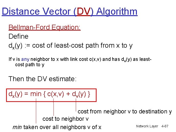
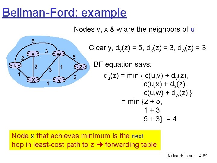
Distance Vector (DV) Algorithm Bellman-Ford Equation: Define dx(y) : = cost of least-cost path from x to y If v is any neighbor to x with link cost c(x, v) and has dv(y) as leastcost path to y Then the DV estimate: dx(y) = min { c(x, v) + dv(y) } cost from neighbor v to destination y cost to neighbor v Network Layer 4 -87 min taken over all neighbors v of x
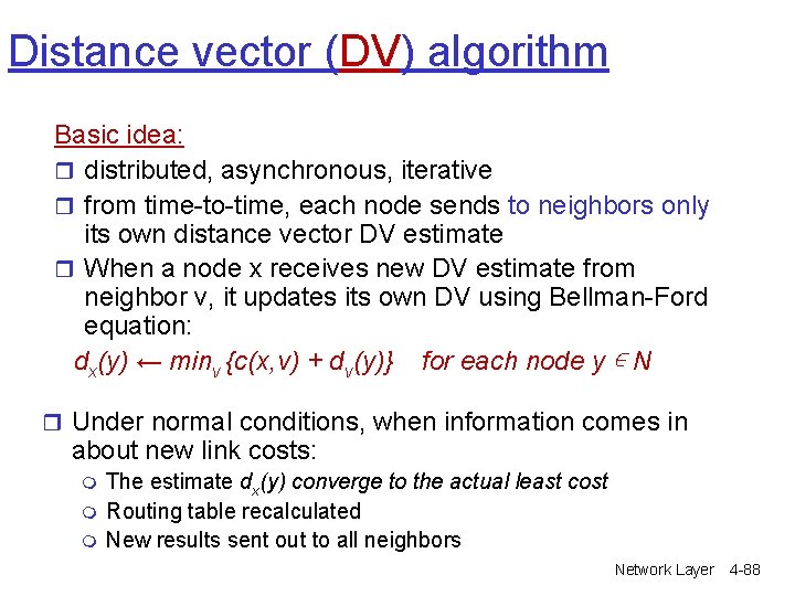
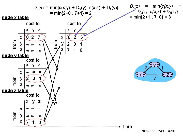
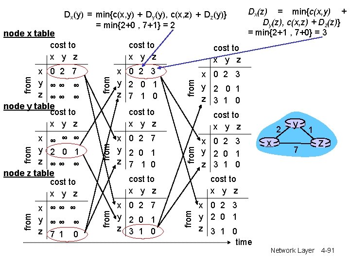
Distance vector (DV) algorithm Basic idea: r distributed, asynchronous, iterative r from time-to-time, each node sends to neighbors only its own distance vector DV estimate r When a node x receives new DV estimate from neighbor v, it updates its own DV using Bellman-Ford equation: dx(y) ← minv {c(x, v) + dv(y)} for each node y ∊ N r Under normal conditions, when information comes in about new link costs: m m m The estimate dx(y) converge to the actual least cost Routing table recalculated New results sent out to all neighbors Network Layer 4 -88
Bellman-Ford: example Nodes v, x & w are the neighbors of u 5 2 u v 2 1 x 3 w 3 1 Clearly, dv(z) = 5, dx(z) = 3, dw(z) = 3 5 z 1 y 2 BF equation says: du(z) = min { c(u, v) + dv(z), c(u, x) + dx(z), c(u, w) + dw(z) } = min {2 + 5, 1 + 3, 5 + 3} = 4 Node x that achieves minimum is the next hop in least-cost path to z ➜ forwarding table Network Layer 4 -89
Dx(y) = min{c(x, y) + Dy(y), c(x, z) + Dz(y)} = min{2+0 , 7+1} = 2 node x table cost to x y z from x 0 2 7 y ∞∞ ∞ z ∞∞ ∞ node y table cost to x y z Dx(z) = min{c(x, y) + Dy(z), c(x, z) + Dz(z)} = min{2+1 , 7+0} = 3 x 0 2 3 y 2 0 1 z 7 1 0 2 x ∞ ∞ ∞ y 2 0 1 z ∞∞ ∞ node z table cost to x y z from x x ∞∞ ∞ y ∞∞ ∞ z 7 1 0 y 1 7 z time Network Layer 4 -90
Dx(y) = min{c(x, y) + Dy(y), c(x, z) + Dz(y)} = min{2+0 , 7+1} = 2 x ∞∞ ∞ y ∞∞ ∞ z 7 1 0 x 0 2 3 y 2 0 1 z 3 1 0 from cost to x y z x 0 2 7 y 2 0 1 z 7 1 0 x 0 2 3 y 2 0 1 z 3 1 0 from cost to x y z x 0 2 7 y 2 0 1 z 3 1 0 2 x y 1 7 z cost to x y z from x ∞ ∞ ∞ y 2 0 1 z ∞∞ ∞ node z table cost to x y z from x 0 2 7 y ∞∞ ∞ z ∞∞ ∞ node y table cost to x y z from node x table cost to x y z Dx(z) = min{c(x, y) + Dy(z), c(x, z) + Dz(z)} = min{2+1 , 7+0} = 3 x 0 2 3 y 2 0 1 z 3 1 0 time Network Layer 4 -91
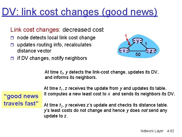
DV: link cost changes (good news) Link cost changes: decreased cost r node detects local link cost change 1 4 r updates routing info, recalculates distance vector r if DV changes, notify neighbors x y 50 1 z At time t 0, y detects the link-cost change, updates its DV, and informs its neighbors. “good news travels fast” At time t 1, z receives the update from y and updates its table. It computes a new least cost to x and sends its neighbors its DV. At time t 2, y receives z’s update and checks its distance table. y’s least costs do not change and hence y does not send any update to z. Network Layer 4 -92
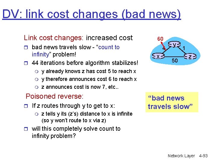
DV: link cost changes (bad news) Link cost changes: increased cost 60 r bad news travels slow - “count to infinity” problem! r 44 iterations before algorithm stabilizes! m m m x y 50 1 z y already knows z has cost 5 to reach x y therefore announces cost 6 to reach x z announces cost is now 7, etc. . Poisoned reverse: r If z routes through y to get to x: m 4 “bad news travels slow” z tells y its (z’s) distance to x is infinite (so y won’t route to x via z) r will this completely solve count to infinity problem? Network Layer 4 -93
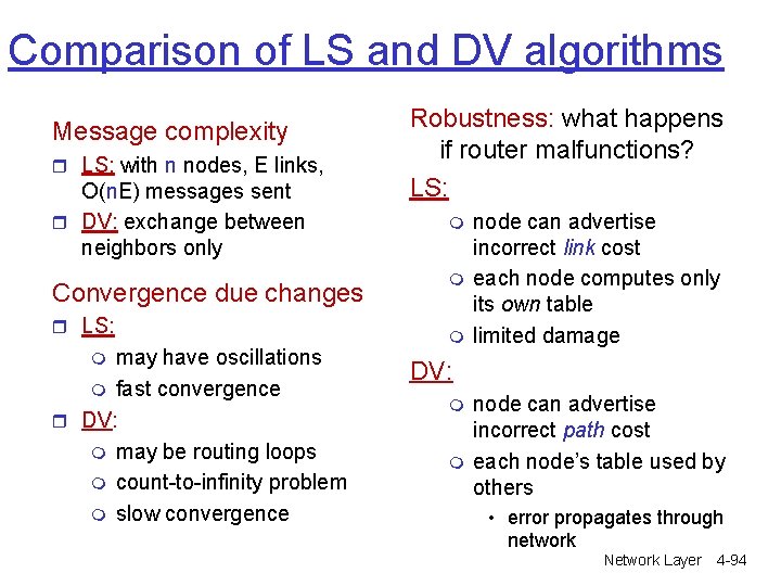
Comparison of LS and DV algorithms Message complexity r LS: with n nodes, E links, O(n. E) messages sent r DV: exchange between neighbors only Convergence due changes r LS: may have oscillations m fast convergence r DV: m may be routing loops m count-to-infinity problem m slow convergence m Robustness: what happens if router malfunctions? LS: m m m node can advertise incorrect link cost each node computes only its own table limited damage DV: m m node can advertise incorrect path cost each node’s table used by others • error propagates through network Network Layer 4 -94
Chapter 4: Network Layer r 4. 1 Introduction r 4. 2 Virtual circuit and datagram networks r 4. 3 What’s inside a router r 4. 4 IP: Internet Protocol m m Datagram format IPv 4 addressing ICMP IPv 6 r 4. 5 Routing algorithms m Link state m Distance Vector m Hierarchical routing r 4. 6 Routing in the Internet m m m RIP OSPF BGP r 4. 7 Broadcast and multicast routing Network Layer 4 -95
Hierarchical Routing Our routing study thus far - idealization r all routers identical r network “flat” … not true in practice scale: millions of destinations! administrative autonomy r can’t store all destinations in r Internet = network of networks routing tables! r LS routing info exchange would swamp links! r DV would never terminate r each network administrator may want to control routing in its own network Network Layer 4 -96
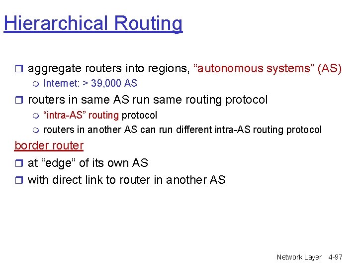
Hierarchical Routing r aggregate routers into regions, “autonomous systems” (AS) m Internet: > 39, 000 AS r routers in same AS run same routing protocol m “intra-AS” routing protocol m routers in another AS can run different intra-AS routing protocol border router r at “edge” of its own AS r with direct link to router in another AS Network Layer 4 -97
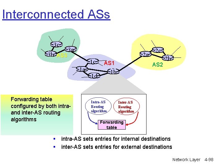
Interconnected ASs 3 c 3 b AS 3 3 a 2 a 1 c 1 a Forwarding table configured by both intraand inter-AS routing algorithms AS 1 2 c AS 2 2 b 1 b 1 d Intra-AS Routing algorithm Inter-AS Routing algorithm Forwarding table § intra-AS sets entries for internal destinations § inter-AS sets entries for external destinations Network Layer 4 -98
Chapter 4: Network Layer r 4. 1 Introduction r 4. 2 Virtual circuit and datagram networks r 4. 3 What’s inside a router r 4. 4 IP: Internet Protocol m m Datagram format IPv 4 addressing ICMP IPv 6 r 4. 5 Routing algorithms m Link state m Distance Vector m Hierarchical routing r 4. 6 Routing in the Internet m m m RIP OSPF BGP r 4. 7 Broadcast and multicast routing Network Layer 4 -99
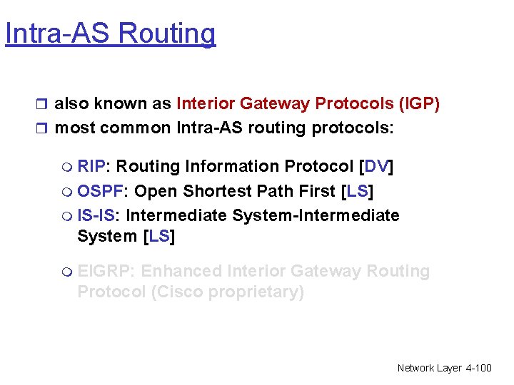
Intra-AS Routing r also known as Interior Gateway Protocols (IGP) r most common Intra-AS routing protocols: m RIP: Routing Information Protocol [DV] m OSPF: Open Shortest Path First [LS] m IS-IS: Intermediate System-Intermediate System [LS] m EIGRP: Enhanced Interior Gateway Routing Protocol (Cisco proprietary) Network Layer 4 -100
Chapter 4: Network Layer r 4. 1 Introduction r 4. 2 Virtual circuit and datagram networks r 4. 3 What’s inside a router r 4. 4 IP: Internet Protocol m m Datagram format IPv 4 addressing ICMP IPv 6 r 4. 5 Routing algorithms m Link state m Distance Vector m Hierarchical routing r 4. 6 Routing in the Internet m m m RIP OSPF BGP r 4. 7 Broadcast and multicast routing Network Layer 4 -101
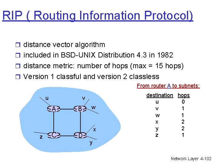
RIP ( Routing Information Protocol) r distance vector algorithm r included in BSD-UNIX Distribution 4. 3 in 1982 r distance metric: number of hops (max = 15 hops) r Version 1 classful and version 2 classless From router A to subnets: u v A z C B w x D destination hops u 0 v 1 w 1 x 2 y 2 z 1 y Network Layer 4 -102
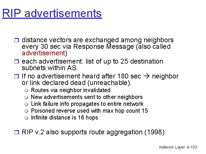
RIP advertisements r distance vectors are exchanged among neighbors every 30 sec via Response Message (also called advertisement) r each advertisement: list of up to 25 destination subnets within AS r If no advertisement heard after 180 sec neighbor or link declared dead (unreachable). m m m Routes via neighbor invalidated New advertisements sent to other neighbors Link failure info propagates to entire network Poisoned reverse used with max hop count 15 Infinite distance is 16 hops r RIP v. 2 also supports route aggregation (1998) Network Layer 4 -103
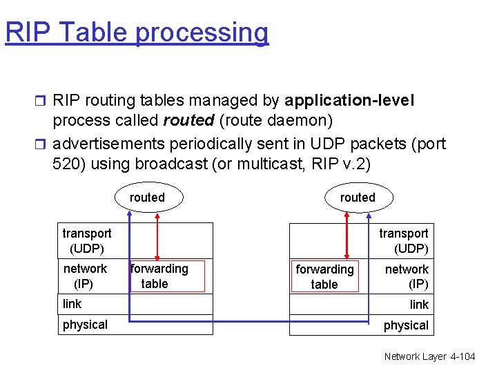
RIP Table processing r RIP routing tables managed by application-level process called routed (route daemon) r advertisements periodically sent in UDP packets (port 520) using broadcast (or multicast, RIP v. 2) routed transport (UDP) network (IP) link physical transport (UDP) forwarding table network (IP) link physical Network Layer 4 -104
Chapter 4: Network Layer r 4. 1 Introduction r 4. 2 Virtual circuit and datagram networks r 4. 3 What’s inside a router r 4. 4 IP: Internet Protocol m m Datagram format IPv 4 addressing ICMP IPv 6 r 4. 5 Routing algorithms m Link state m Distance Vector m Hierarchical routing r 4. 6 Routing in the Internet m m m RIP OSPF BGP r 4. 7 Broadcast and multicast routing Network Layer 4 -105
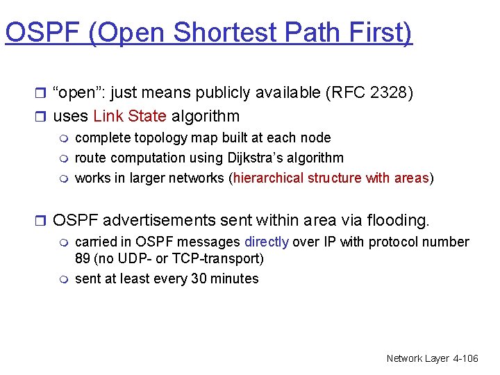
OSPF (Open Shortest Path First) r “open”: just means publicly available (RFC 2328) r uses Link State algorithm m complete topology map built at each node m route computation using Dijkstra’s algorithm m works in larger networks (hierarchical structure with areas) r OSPF advertisements sent within area via flooding. m carried in OSPF messages directly over IP with protocol number 89 (no UDP- or TCP-transport) m sent at least every 30 minutes Network Layer 4 -106
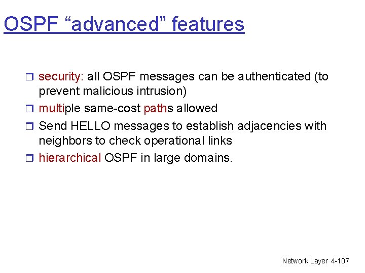
OSPF “advanced” features r security: all OSPF messages can be authenticated (to prevent malicious intrusion) r multiple same-cost paths allowed r Send HELLO messages to establish adjacencies with neighbors to check operational links r hierarchical OSPF in large domains. Network Layer 4 -107
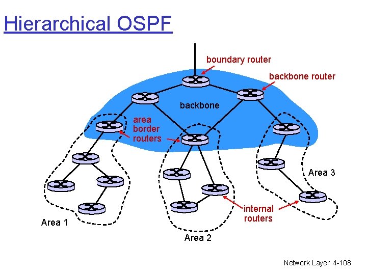
Hierarchical OSPF boundary router backbone area border routers Area 3 internal routers Area 1 Area 2 Network Layer 4 -108
Hierarchical OSPF r two-level hierarchy: local areas, one backbone (area 0). m Link-state advertisements only in area m each node has detailed area topology; only knows direction (shortest path) to subnets in other areas. r area border routers: “summarize” subnets in own area, advertise to other area border routers. r backbone routers: run OSPF routing limited to backbone. r boundary routers: connect to other AS’s. Network Layer 4 -109
Chapter 4: Network Layer r 4. 1 Introduction r 4. 2 Virtual circuit and datagram networks r 4. 3 What’s inside a router r 4. 4 IP: Internet Protocol m m Datagram format IPv 4 addressing ICMP IPv 6 r 4. 5 Routing algorithms m Link state m Distance Vector m Hierarchical routing r 4. 6 Routing in the Internet m m m RIP OSPF BGP r 4. 7 Broadcast and multicast routing Network Layer 4 -110
Internet inter-AS routing: BGP r BGP (Border Gateway Protocol) m m m the de facto standard routing protocol on the Internet Complex protocol Communicates over TCP port 179 with authentication r BGP provides each AS a means to: o Obtain prefix reachability information from neighboring ASs. o Propagate reachability information to all ASinternal routers. o Determine “good” routes to prefixes based on reachability information and policy. Network Layer 4 -111
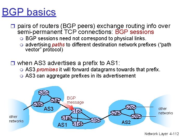
BGP basics r pairs of routers (BGP peers) exchange routing info over semi-permanent TCP connections: BGP sessions m m BGP sessions need not correspond to physical links. advertising paths to different destination network prefixes (“path vector” protocol) r when AS 3 advertises a prefix to AS 1: m AS 3 promises it will forward datagrams towards that prefix. m AS 3 can aggregate prefixes in its advertisement 3 c 3 b other networks 3 a BGP message AS 3 1 c 1 a AS 1 1 d 2 a 1 b 2 c 2 b other networks AS 2 Network Layer 4 -112
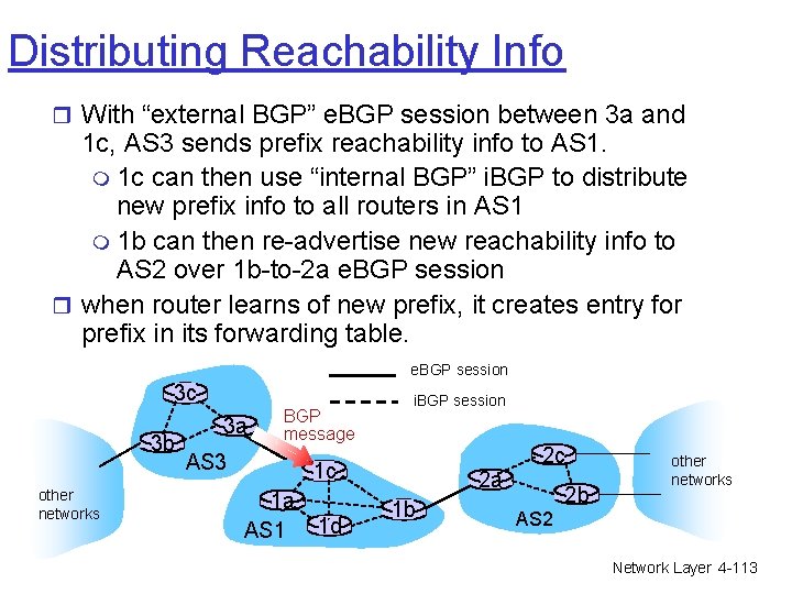
Distributing Reachability Info r With “external BGP” e. BGP session between 3 a and 1 c, AS 3 sends prefix reachability info to AS 1. m 1 c can then use “internal BGP” i. BGP to distribute new prefix info to all routers in AS 1 m 1 b can then re-advertise new reachability info to AS 2 over 1 b-to-2 a e. BGP session r when router learns of new prefix, it creates entry for prefix in its forwarding table. e. BGP session 3 c 3 b other networks 3 a BGP message AS 3 i. BGP session 1 c 1 a AS 1 1 d 2 a 1 b 2 c 2 b other networks AS 2 Network Layer 4 -113
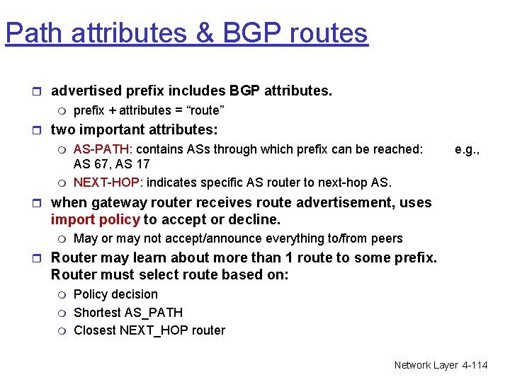
Path attributes & BGP routes r advertised prefix includes BGP attributes. m prefix + attributes = “route” r two important attributes: m m AS-PATH: contains ASs through which prefix can be reached: AS 67, AS 17 NEXT-HOP: indicates specific AS router to next-hop AS. e. g. , r when gateway router receives route advertisement, uses import policy to accept or decline. m May or may not accept/announce everything to/from peers r Router may learn about more than 1 route to some prefix. Router must select route based on: m m m Policy decision Shortest AS_PATH Closest NEXT_HOP router Network Layer 4 -114
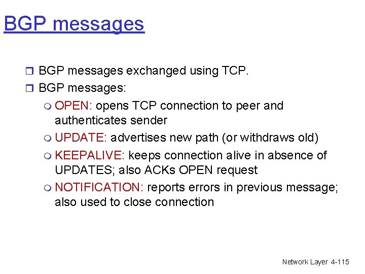
BGP messages r BGP messages exchanged using TCP. r BGP messages: m OPEN: opens TCP connection to peer and authenticates sender m UPDATE: advertises new path (or withdraws old) m KEEPALIVE: keeps connection alive in absence of UPDATES; also ACKs OPEN request m NOTIFICATION: reports errors in previous message; also used to close connection Network Layer 4 -115
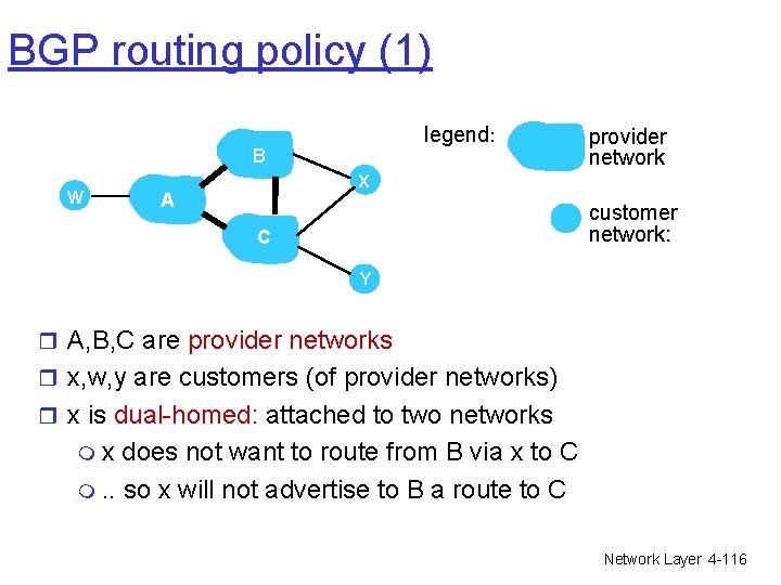
BGP routing policy (1) legend: B W provider network X A customer network: C Y r A, B, C are provider networks r x, w, y are customers (of provider networks) r x is dual-homed: attached to two networks mx does not want to route from B via x to C m. . so x will not advertise to B a route to C Network Layer 4 -116
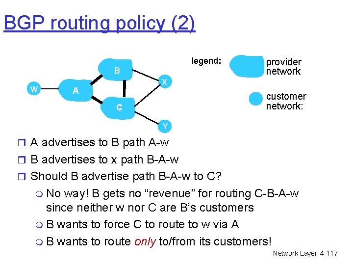
BGP routing policy (2) legend: B W provider network X A customer network: C Y r A advertises to B path A-w r B advertises to x path B-A-w r Should B advertise path B-A-w to C? m No way! B gets no “revenue” for routing C-B-A-w since neither w nor C are B’s customers m B wants to force C to route to w via A m B wants to route only to/from its customers! Network Layer 4 -117
Why different Intra- & Inter-AS routing? Policy: r Inter-AS: admin wants control over how its traffic routed, who routes through its net. r Intra-AS: single admin, so no policy decisions needed Scale: r hierarchical routing saves routing table size, reduced update traffic Performance: r Inter-AS: policy may dominate over performance r Intra-AS: can focus on performance Network Layer 4 -118
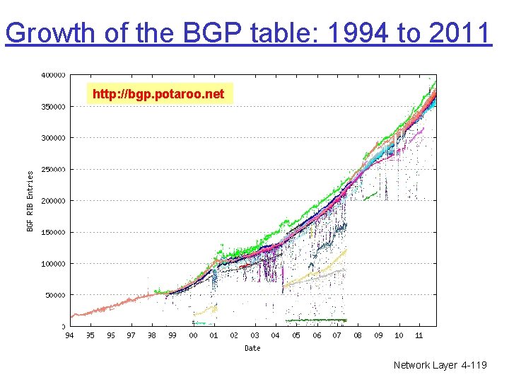
Growth of the BGP table: 1994 to 2011 http: //bgp. potaroo. net Network Layer 4 -119
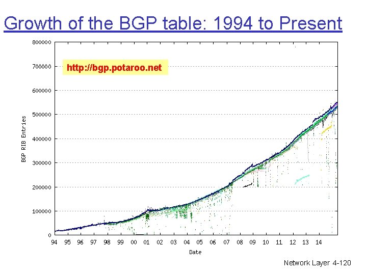
Growth of the BGP table: 1994 to Present http: //bgp. potaroo. net Network Layer 4 -120
Chapter 4: Network Layer r 4. 1 Introduction r 4. 2 Virtual circuit and datagram networks r 4. 3 What’s inside a router r 4. 4 IP: Internet Protocol m m Datagram format IPv 4 addressing ICMP IPv 6 r 4. 5 Routing algorithms m Link state m Distance Vector m Hierarchical routing r 4. 6 Routing in the Internet m m m RIP OSPF BGP r 4. 7 Broadcast and multicast routing Network Layer 4 -121