CS 1302 Computer Networks Unit 3 Network Layer
- Slides: 95
CS 1302 Computer Networks — Unit - 3 — — Network Layer — n Text Book Behrouz. A. Forouzan, “Data communication and Networking”, Tata Mc. Graw. Hill, 2004 12/4/2020 Unit-3 : Network Layer 1
Network Layer 12/4/2020 Unit-3 : Network Layer 2
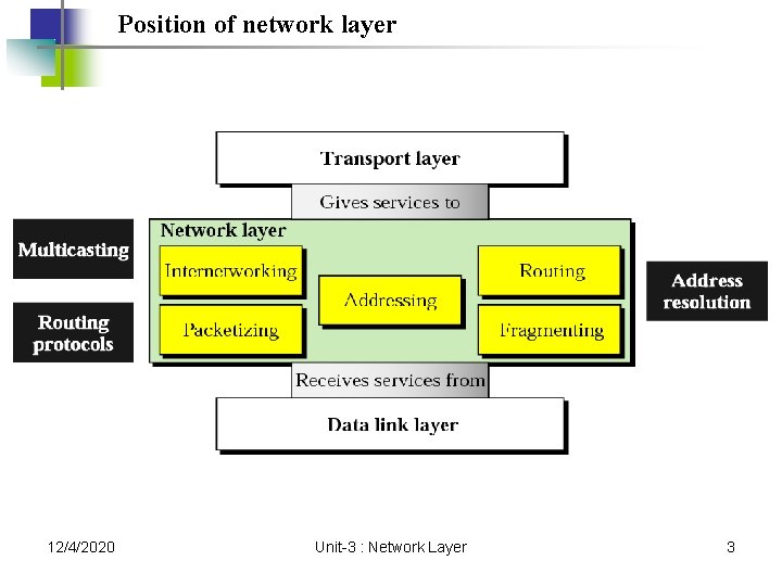
Position of network layer 12/4/2020 Unit-3 : Network Layer 3
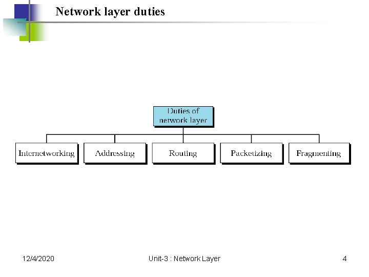
Network layer duties 12/4/2020 Unit-3 : Network Layer 4
Host-to-Host Delivery: Internetworking, Addressing, and Routing 12/4/2020 Unit-3 : Network Layer 5
19. 1 Internetworks Need For Network Layer Internet As A Packet-Switched Network Internet As A Connectionless Network 12/4/2020 Unit-3 : Network Layer 6
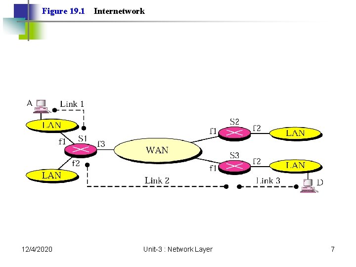
Figure 19. 1 12/4/2020 Internetwork Unit-3 : Network Layer 7
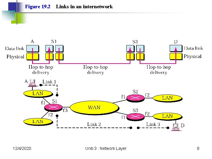
Figure 19. 2 12/4/2020 Links in an internetwork Unit-3 : Network Layer 8
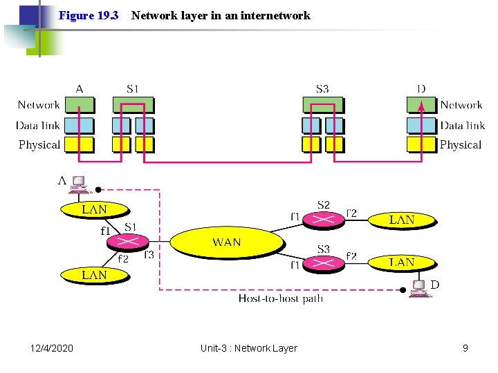
Figure 19. 3 12/4/2020 Network layer in an internetwork Unit-3 : Network Layer 9
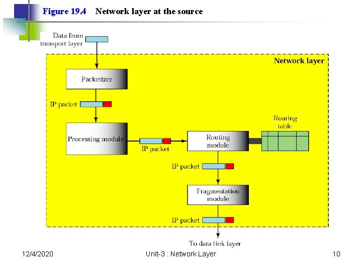
Figure 19. 4 12/4/2020 Network layer at the source Unit-3 : Network Layer 10
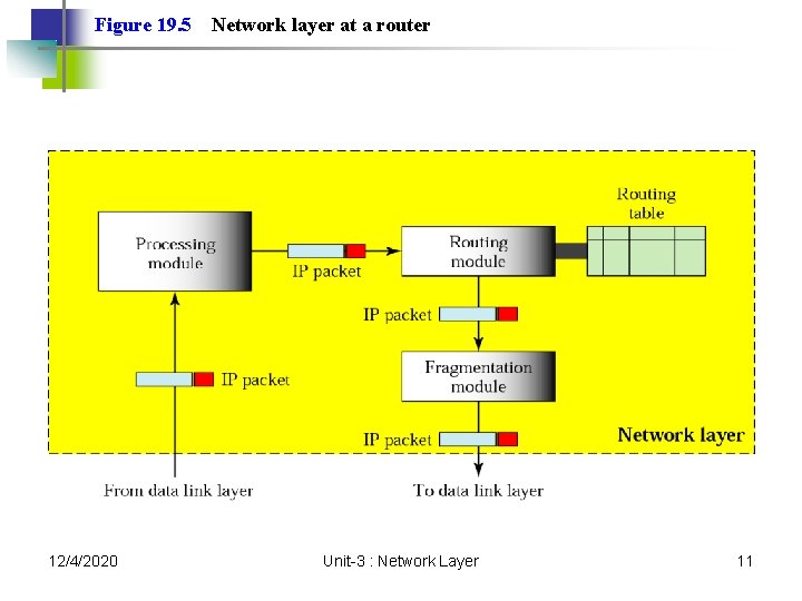
Figure 19. 5 12/4/2020 Network layer at a router Unit-3 : Network Layer 11
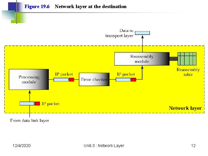
Figure 19. 6 12/4/2020 Network layer at the destination Unit-3 : Network Layer 12
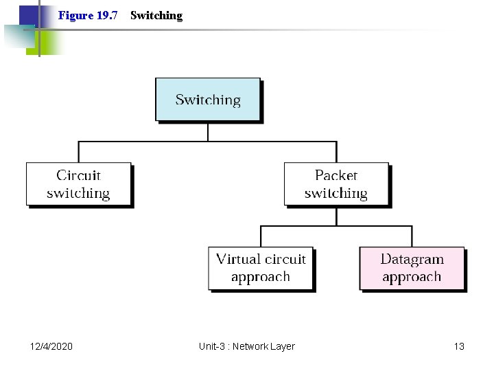
Figure 19. 7 12/4/2020 Switching Unit-3 : Network Layer 13
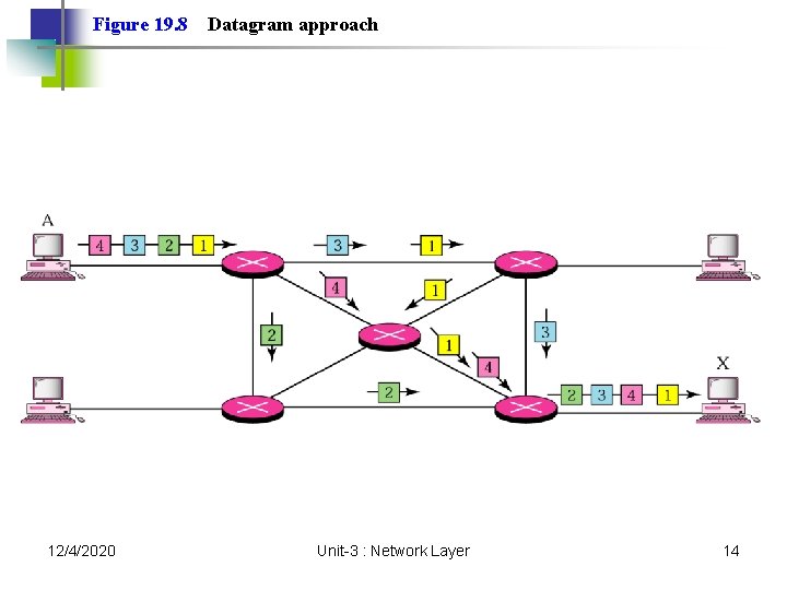
Figure 19. 8 12/4/2020 Datagram approach Unit-3 : Network Layer 14
Note: Switching at the network layer in the Internet is done using the datagram approach to packet switching. 12/4/2020 Unit-3 : Network Layer 15
Note: Communication at the network layer in the Internet is connectionless. 12/4/2020 Unit-3 : Network Layer 16
19. 2 Addressing Internet Address Classful Addressing Subnetting Supernetting Classless Addressing Dynamic Address Configuration Network Address Translation 12/4/2020 Unit-3 : Network Layer 17
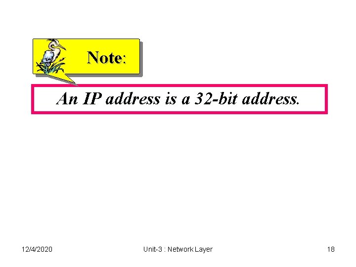
Note: An IP address is a 32 -bit address. 12/4/2020 Unit-3 : Network Layer 18
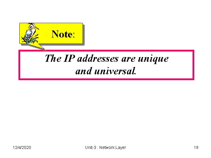
Note: The IP addresses are unique and universal. 12/4/2020 Unit-3 : Network Layer 19
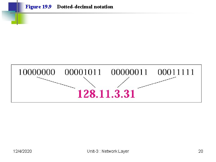
Figure 19. 9 12/4/2020 Dotted-decimal notation Unit-3 : Network Layer 20
Note: The binary, decimal, and hexadecimal number systems are reviewed in Appendix B. 12/4/2020 Unit-3 : Network Layer 21
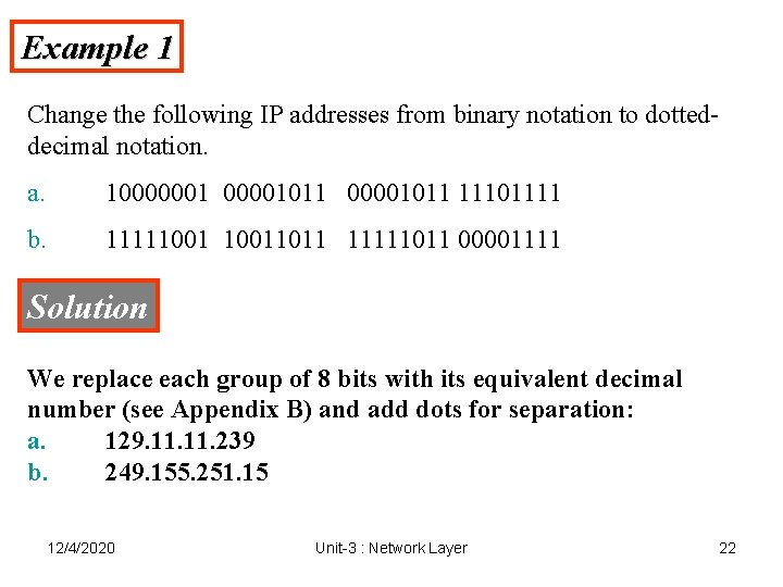
Example 1 Change the following IP addresses from binary notation to dotteddecimal notation. a. 10000001011 11101111 b. 111110011011 11111011 00001111 Solution We replace each group of 8 bits with its equivalent decimal number (see Appendix B) and add dots for separation: a. 129. 11. 239 b. 249. 155. 251. 15 12/4/2020 Unit-3 : Network Layer 22
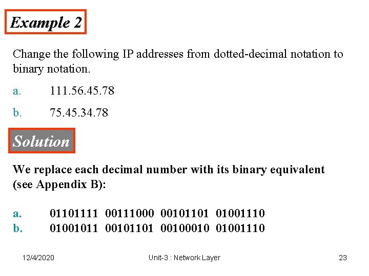
Example 2 Change the following IP addresses from dotted-decimal notation to binary notation. a. 111. 56. 45. 78 b. 75. 45. 34. 78 Solution We replace each decimal number with its binary equivalent (see Appendix B): a. b. 01101111 00111000 00101101 01001110 0100101101 0010 01001110 12/4/2020 Unit-3 : Network Layer 23
Note: In classful addressing, the address space is divided into five classes: A, B, C, D, and E. 12/4/2020 Unit-3 : Network Layer 24
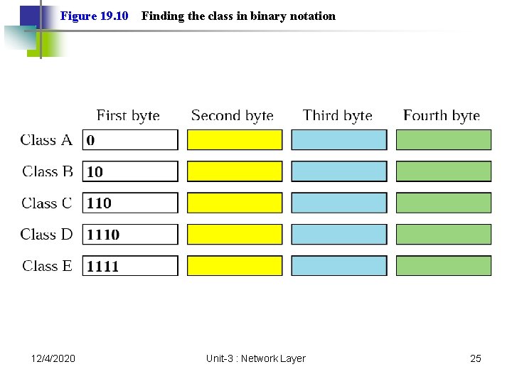
Figure 19. 10 12/4/2020 Finding the class in binary notation Unit-3 : Network Layer 25
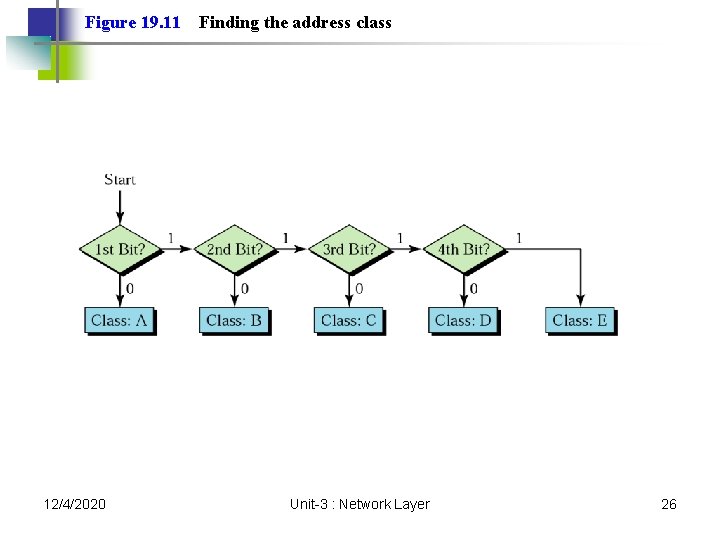
Figure 19. 11 12/4/2020 Finding the address class Unit-3 : Network Layer 26
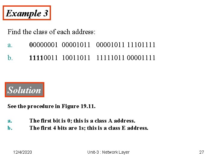
Example 3 Find the class of each address: a. 00000001011 11101111 b. 11110011011 11111011 00001111 Solution See the procedure in Figure 19. 11. a. b. The first bit is 0; this is a class A address. The first 4 bits are 1 s; this is a class E address. 12/4/2020 Unit-3 : Network Layer 27
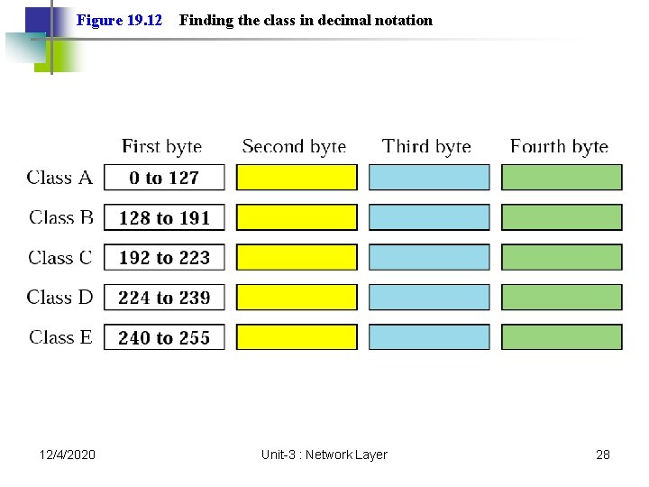
Figure 19. 12 12/4/2020 Finding the class in decimal notation Unit-3 : Network Layer 28
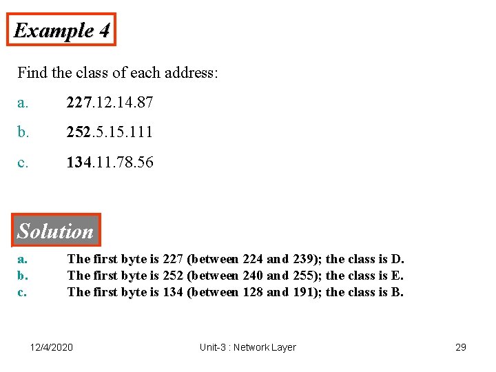
Example 4 Find the class of each address: a. 227. 12. 14. 87 b. 252. 5. 111 c. 134. 11. 78. 56 Solution a. b. c. The first byte is 227 (between 224 and 239); the class is D. The first byte is 252 (between 240 and 255); the class is E. The first byte is 134 (between 128 and 191); the class is B. 12/4/2020 Unit-3 : Network Layer 29
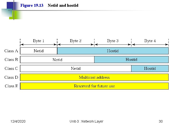
Figure 19. 13 12/4/2020 Netid and hostid Unit-3 : Network Layer 30
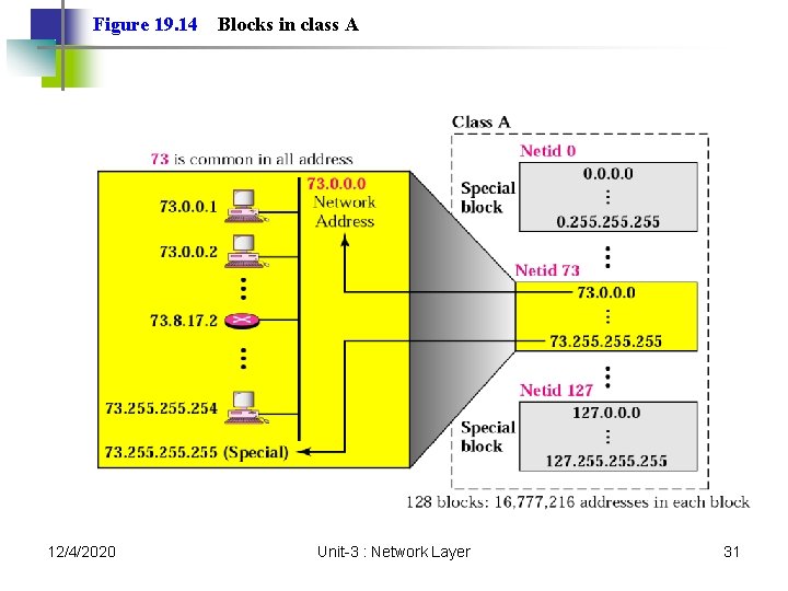
Figure 19. 14 12/4/2020 Blocks in class A Unit-3 : Network Layer 31
Note: Millions of class A addresses are wasted. 12/4/2020 Unit-3 : Network Layer 32
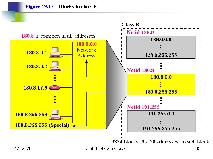
Figure 19. 15 12/4/2020 Blocks in class B Unit-3 : Network Layer 33
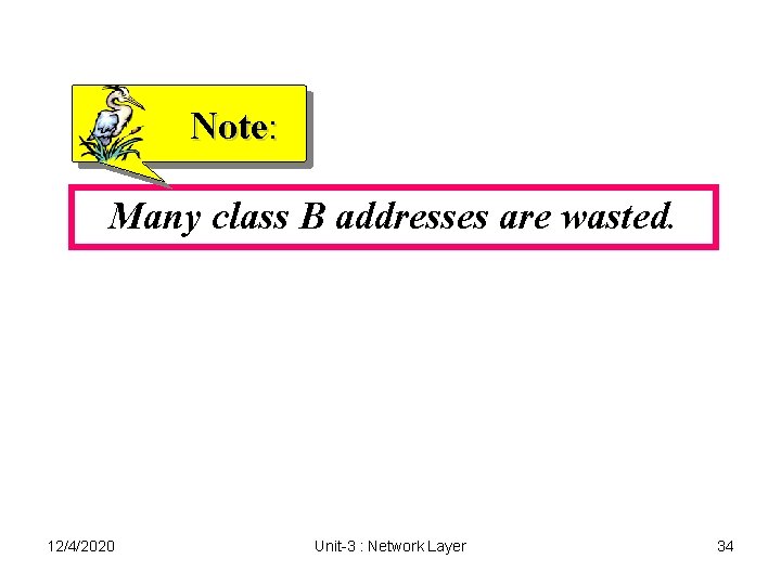
Note: Many class B addresses are wasted. 12/4/2020 Unit-3 : Network Layer 34
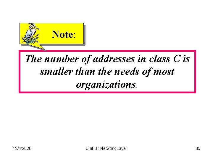
Note: The number of addresses in class C is smaller than the needs of most organizations. 12/4/2020 Unit-3 : Network Layer 35
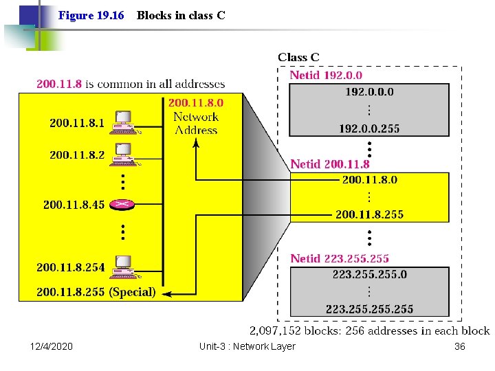
Figure 19. 16 12/4/2020 Blocks in class C Unit-3 : Network Layer 36
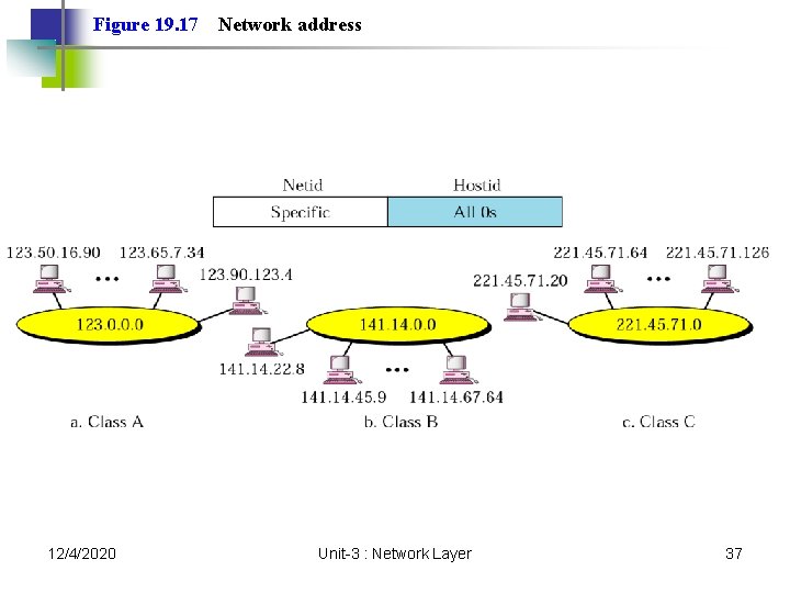
Figure 19. 17 12/4/2020 Network address Unit-3 : Network Layer 37
Note: In classful addressing, the network address is the one that is assigned to the organization. 12/4/2020 Unit-3 : Network Layer 38
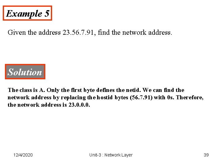
Example 5 Given the address 23. 56. 7. 91, find the network address. Solution The class is A. Only the first byte defines the netid. We can find the network address by replacing the hostid bytes (56. 7. 91) with 0 s. Therefore, the network address is 23. 0. 0. 0. 12/4/2020 Unit-3 : Network Layer 39
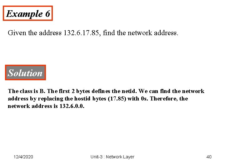
Example 6 Given the address 132. 6. 17. 85, find the network address. Solution The class is B. The first 2 bytes defines the netid. We can find the network address by replacing the hostid bytes (17. 85) with 0 s. Therefore, the network address is 132. 6. 0. 0. 12/4/2020 Unit-3 : Network Layer 40
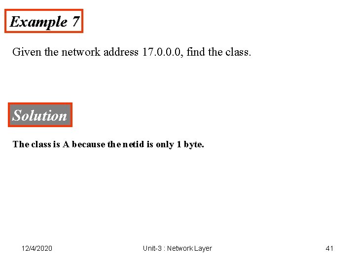
Example 7 Given the network address 17. 0. 0. 0, find the class. Solution The class is A because the netid is only 1 byte. 12/4/2020 Unit-3 : Network Layer 41
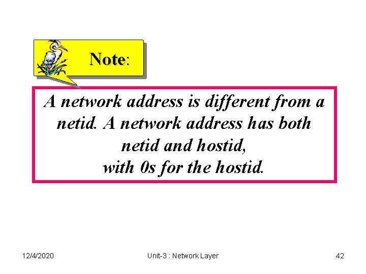
Note: A network address is different from a netid. A network address has both netid and hostid, with 0 s for the hostid. 12/4/2020 Unit-3 : Network Layer 42
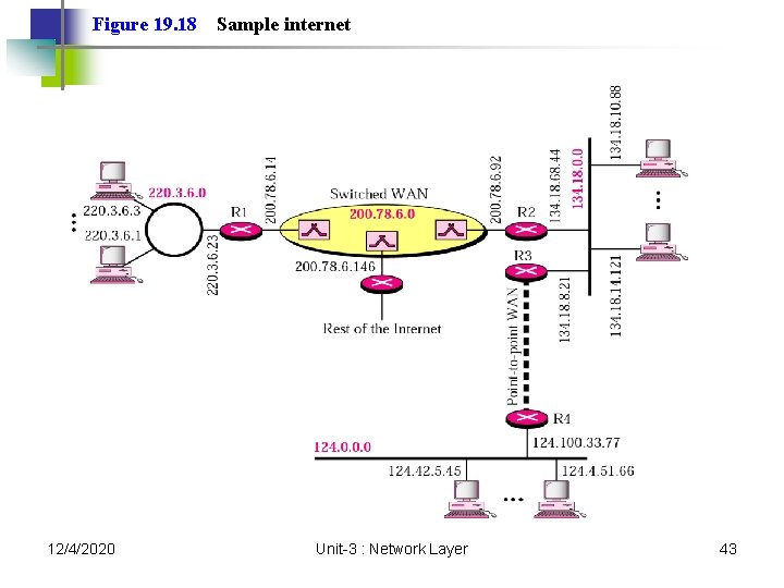
Figure 19. 18 12/4/2020 Sample internet Unit-3 : Network Layer 43
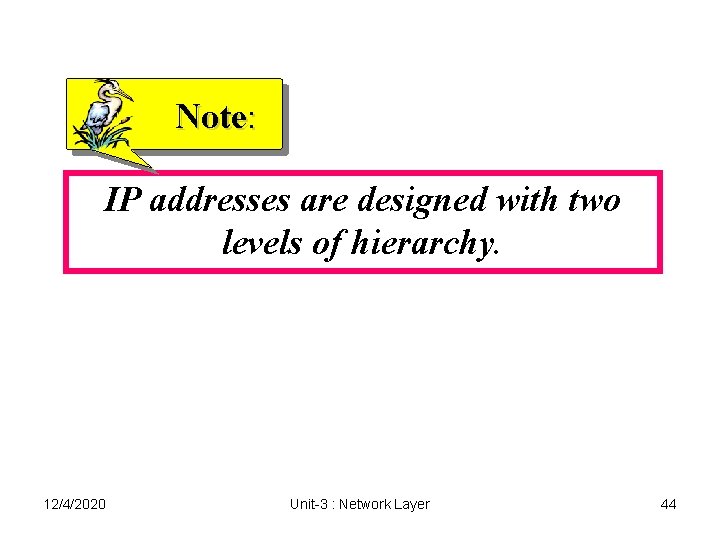
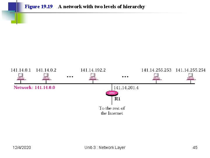
Note: IP addresses are designed with two levels of hierarchy. 12/4/2020 Unit-3 : Network Layer 44
Figure 19. 19 12/4/2020 A network with two levels of hierarchy Unit-3 : Network Layer 45
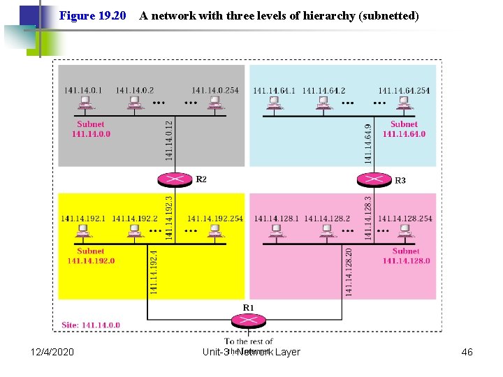
Figure 19. 20 12/4/2020 A network with three levels of hierarchy (subnetted) Unit-3 : Network Layer 46
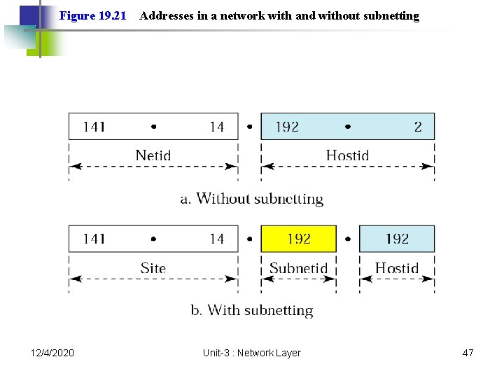
Figure 19. 21 12/4/2020 Addresses in a network with and without subnetting Unit-3 : Network Layer 47
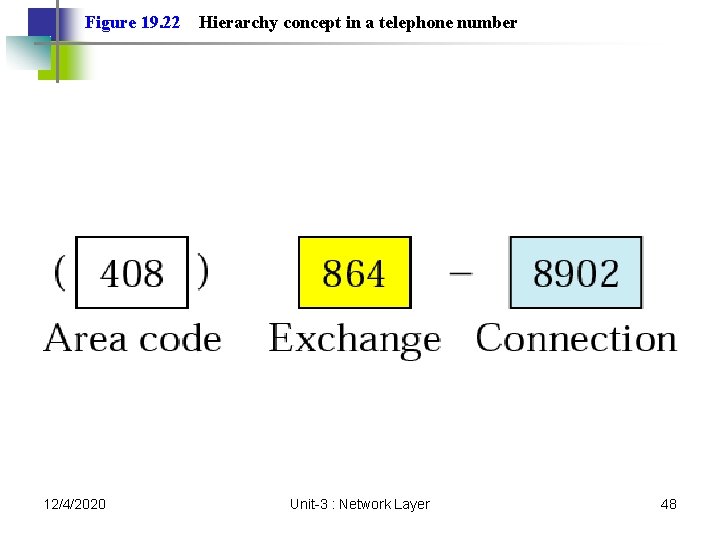
Figure 19. 22 12/4/2020 Hierarchy concept in a telephone number Unit-3 : Network Layer 48
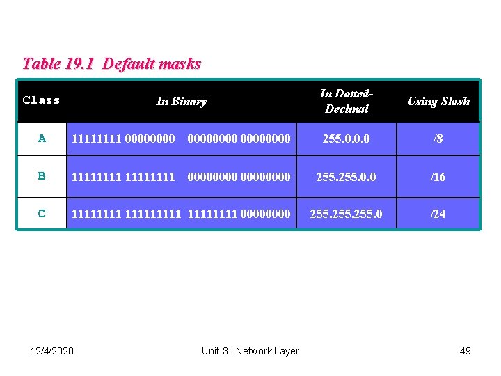
Table 19. 1 Default masks Class In Binary In Dotted. Decimal Using Slash A 1111 00000000 255. 0. 0. 0 /8 B 11111111 00000000 255. 0. 0 /16 C 111111111 0000 255. 0 /24 12/4/2020 Unit-3 : Network Layer 49
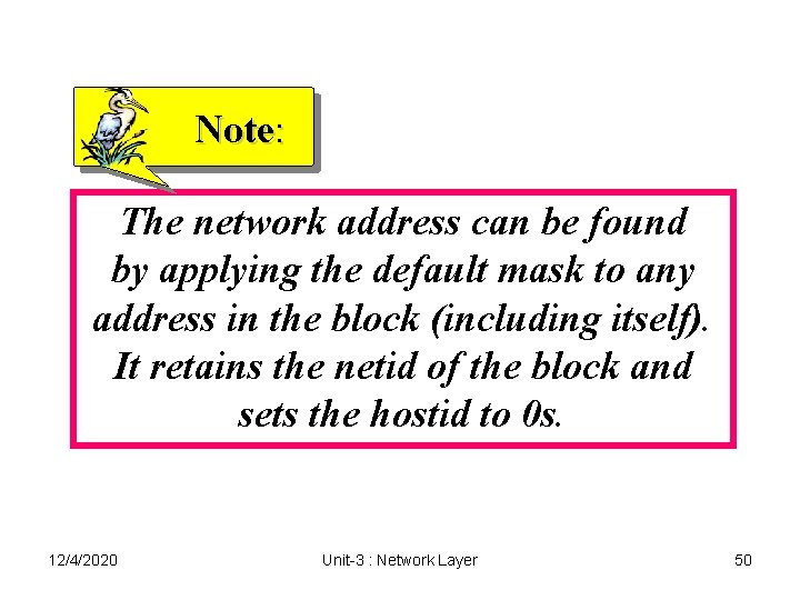
Note: The network address can be found by applying the default mask to any address in the block (including itself). It retains the netid of the block and sets the hostid to 0 s. 12/4/2020 Unit-3 : Network Layer 50
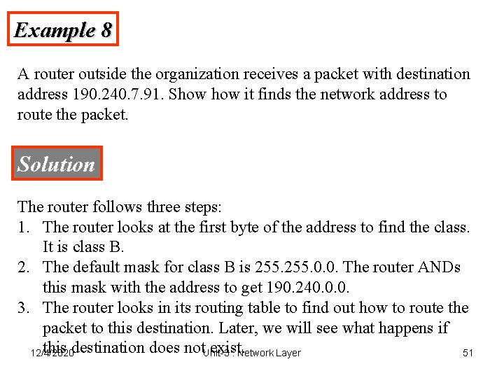
Example 8 A router outside the organization receives a packet with destination address 190. 240. 7. 91. Show it finds the network address to route the packet. Solution The router follows three steps: 1. The router looks at the first byte of the address to find the class. It is class B. 2. The default mask for class B is 255. 0. 0. The router ANDs this mask with the address to get 190. 240. 0. 0. 3. The router looks in its routing table to find out how to route the packet to this destination. Later, we will see what happens if this destination does not. Unit-3 exist. 12/4/2020 : Network Layer 51
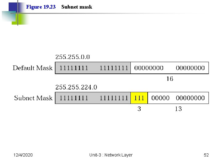
Figure 19. 23 12/4/2020 Subnet mask Unit-3 : Network Layer 52
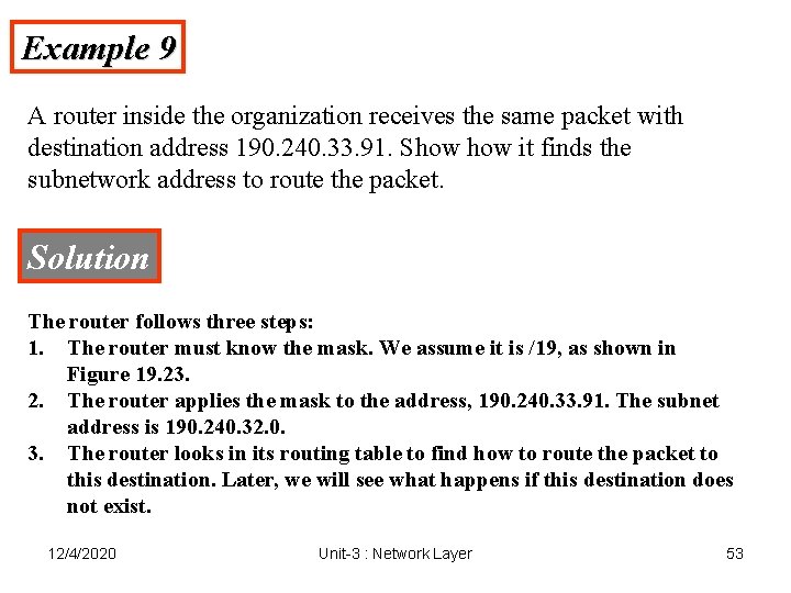
Example 9 A router inside the organization receives the same packet with destination address 190. 240. 33. 91. Show it finds the subnetwork address to route the packet. Solution The router follows three steps: 1. The router must know the mask. We assume it is /19, as shown in Figure 19. 23. 2. The router applies the mask to the address, 190. 240. 33. 91. The subnet address is 190. 240. 32. 0. 3. The router looks in its routing table to find how to route the packet to this destination. Later, we will see what happens if this destination does not exist. 12/4/2020 Unit-3 : Network Layer 53
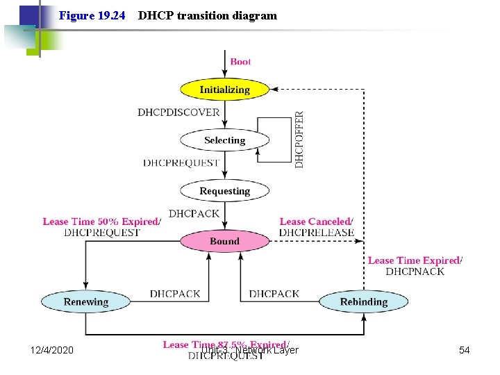
Figure 19. 24 12/4/2020 DHCP transition diagram Unit-3 : Network Layer 54
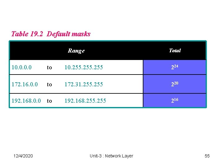
Table 19. 2 Default masks Range Total 10. 0 to 10. 255 224 172. 16. 0. 0 to 172. 31. 255 220 192. 168. 255 216 192. 168. 0. 0 to 12/4/2020 Unit-3 : Network Layer 55
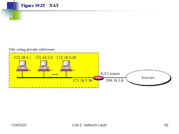
Figure 19. 25 12/4/2020 NAT Unit-3 : Network Layer 56
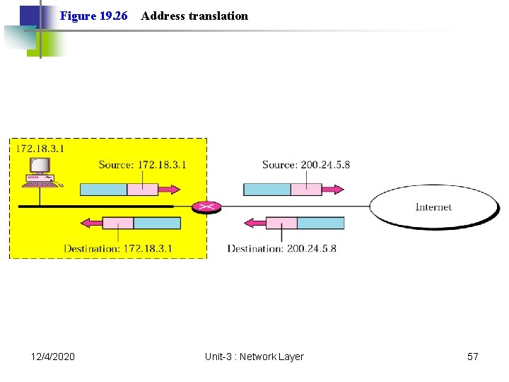
Figure 19. 26 12/4/2020 Address translation Unit-3 : Network Layer 57
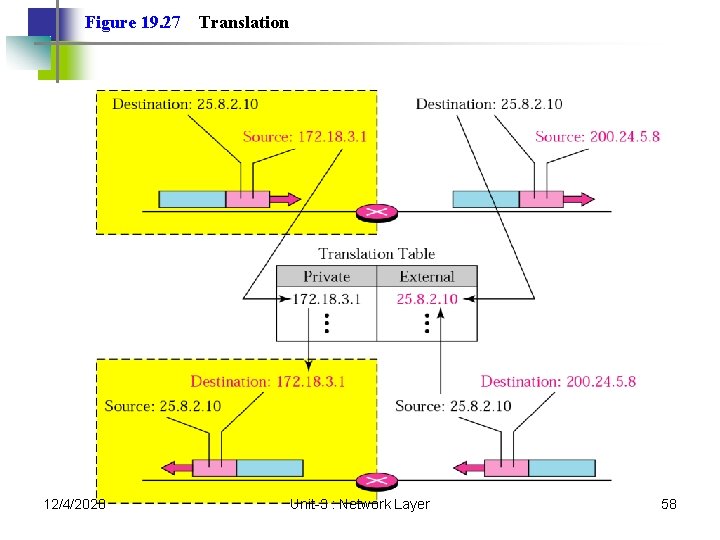
Figure 19. 27 12/4/2020 Translation Unit-3 : Network Layer 58
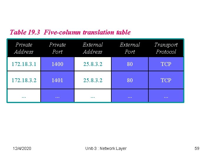
Table 19. 3 Five-column translation table Private Address Private Port External Address External Port Transport Protocol 172. 18. 3. 1 1400 25. 8. 3. 2 80 TCP 172. 18. 3. 2 1401 25. 8. 3. 2 80 TCP . . . . 12/4/2020 Unit-3 : Network Layer 59
19. 3 Routing Techniques Static Versus Dynamic Routing Table for Classful Addressing Routing Table for Classless Addressing 12/4/2020 Unit-3 : Network Layer 60
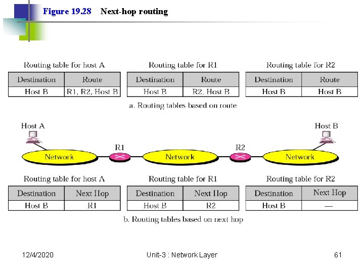
Figure 19. 28 12/4/2020 Next-hop routing Unit-3 : Network Layer 61
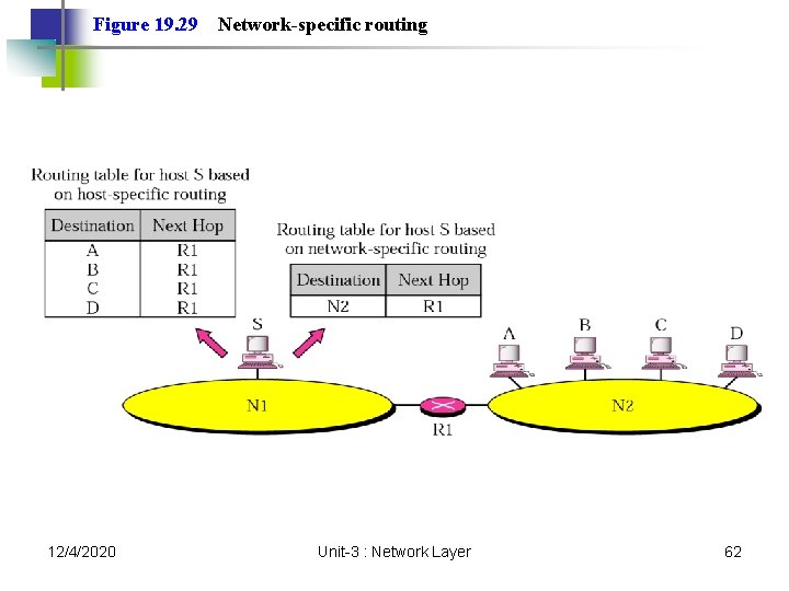
Figure 19. 29 12/4/2020 Network-specific routing Unit-3 : Network Layer 62
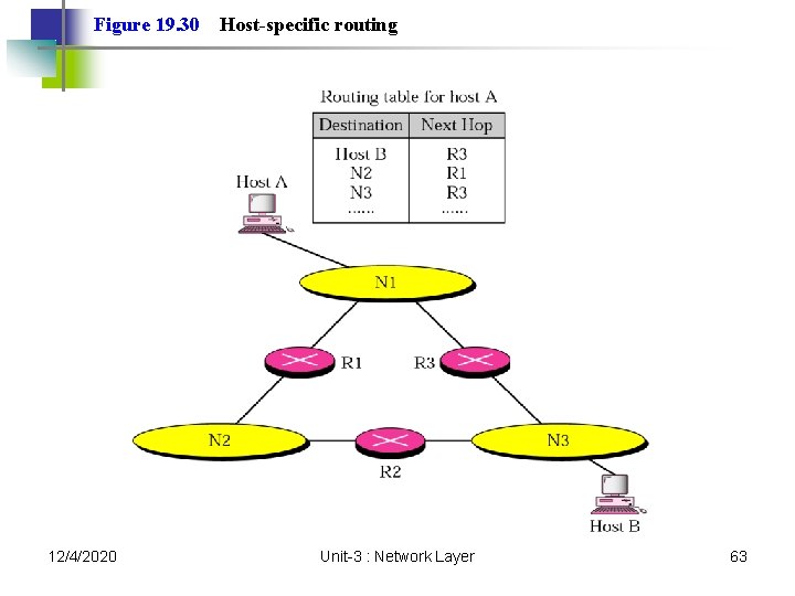
Figure 19. 30 12/4/2020 Host-specific routing Unit-3 : Network Layer 63
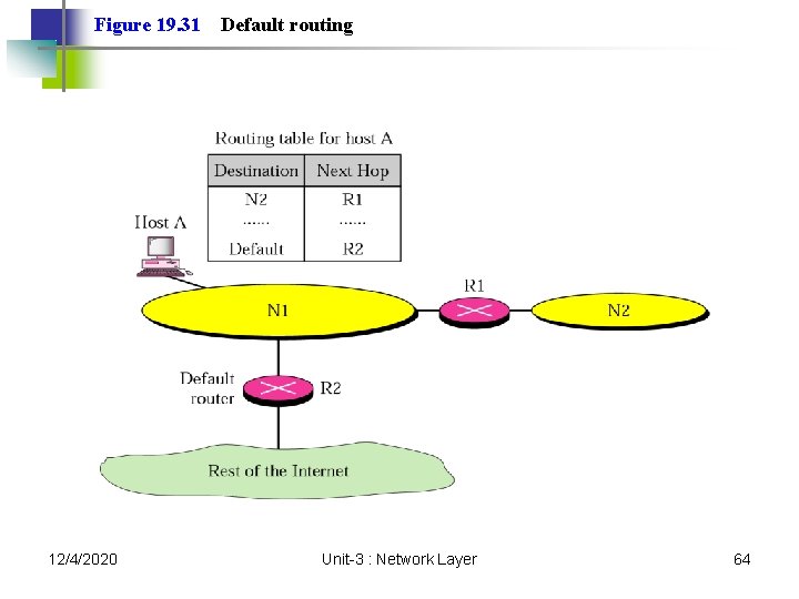
Figure 19. 31 12/4/2020 Default routing Unit-3 : Network Layer 64
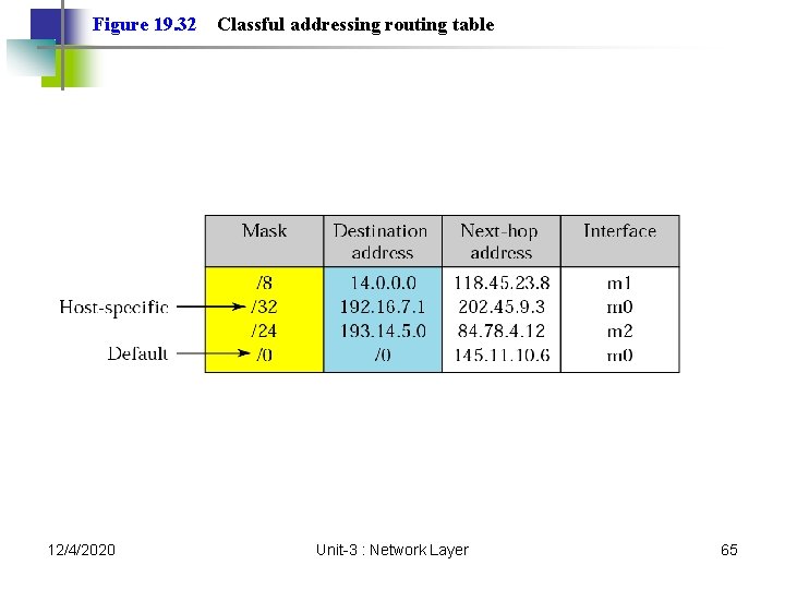
Figure 19. 32 12/4/2020 Classful addressing routing table Unit-3 : Network Layer 65
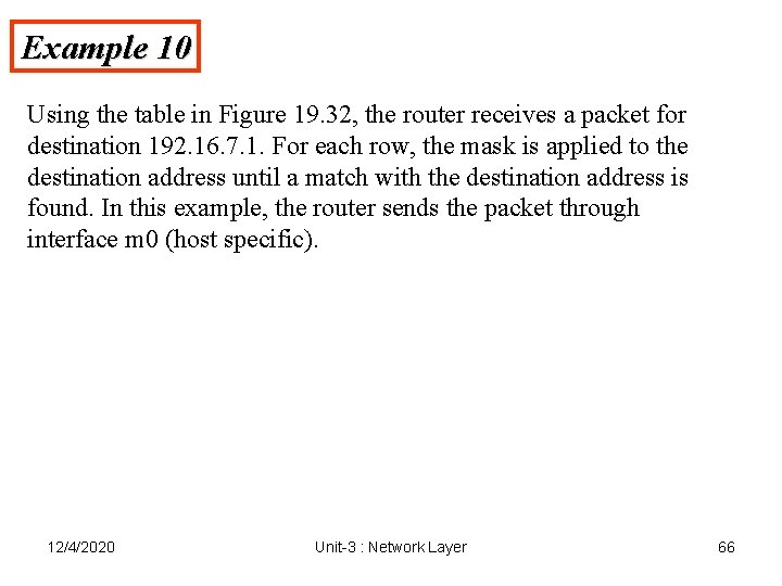
Example 10 Using the table in Figure 19. 32, the router receives a packet for destination 192. 16. 7. 1. For each row, the mask is applied to the destination address until a match with the destination address is found. In this example, the router sends the packet through interface m 0 (host specific). 12/4/2020 Unit-3 : Network Layer 66
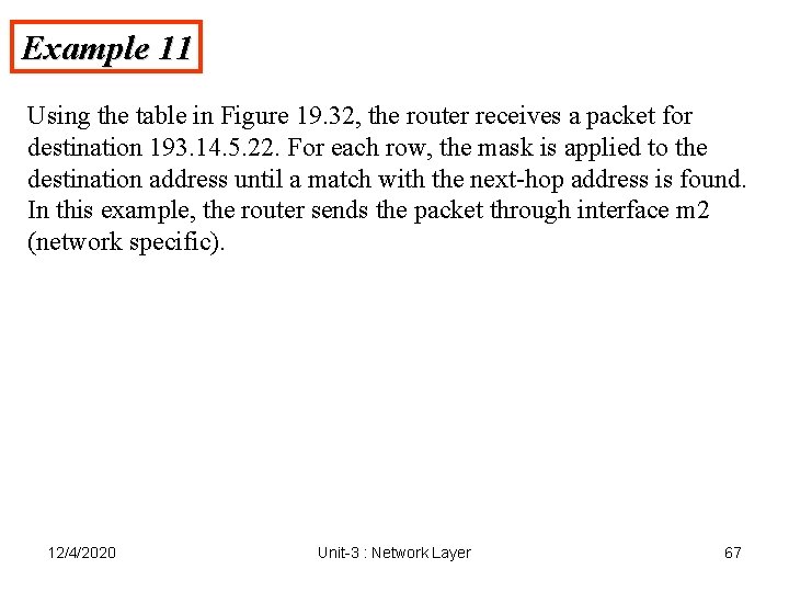
Example 11 Using the table in Figure 19. 32, the router receives a packet for destination 193. 14. 5. 22. For each row, the mask is applied to the destination address until a match with the next-hop address is found. In this example, the router sends the packet through interface m 2 (network specific). 12/4/2020 Unit-3 : Network Layer 67
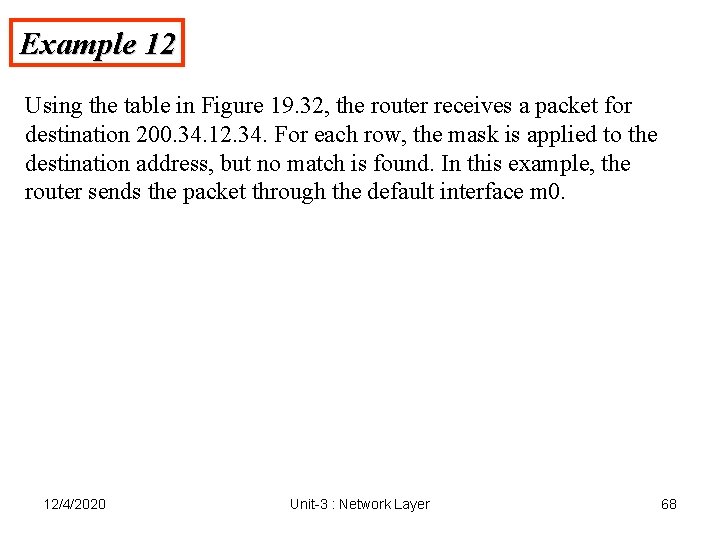
Example 12 Using the table in Figure 19. 32, the router receives a packet for destination 200. 34. 12. 34. For each row, the mask is applied to the destination address, but no match is found. In this example, the router sends the packet through the default interface m 0. 12/4/2020 Unit-3 : Network Layer 68
Routing Algorithms 1. Distance Vector Routing 2. Link State Routing 12/4/2020 Unit-3 : Network Layer 69
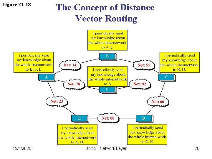
Figure 21 -18 12/4/2020 The Concept of Distance Vector Routing Unit-3 : Network Layer 70
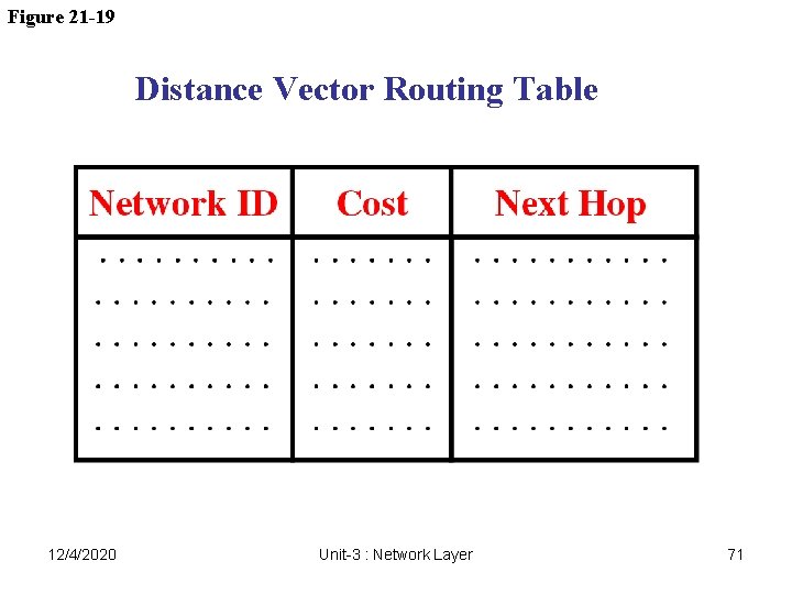
Figure 21 -19 Distance Vector Routing Table 12/4/2020 Unit-3 : Network Layer 71
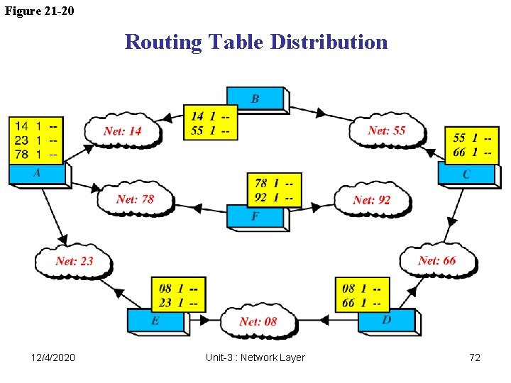
Figure 21 -20 Routing Table Distribution 12/4/2020 Unit-3 : Network Layer 72
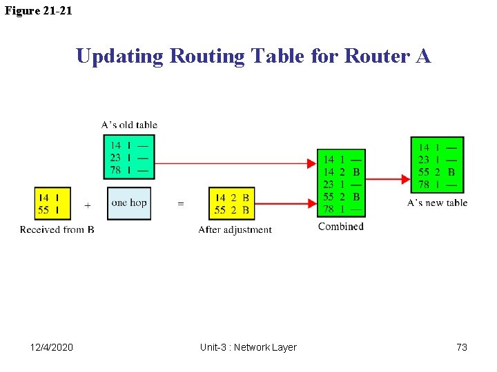
Figure 21 -21 Updating Routing Table for Router A 12/4/2020 Unit-3 : Network Layer 73
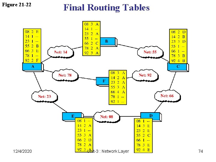
Figure 21 -22 12/4/2020 Final Routing Tables Unit-3 : Network Layer 74
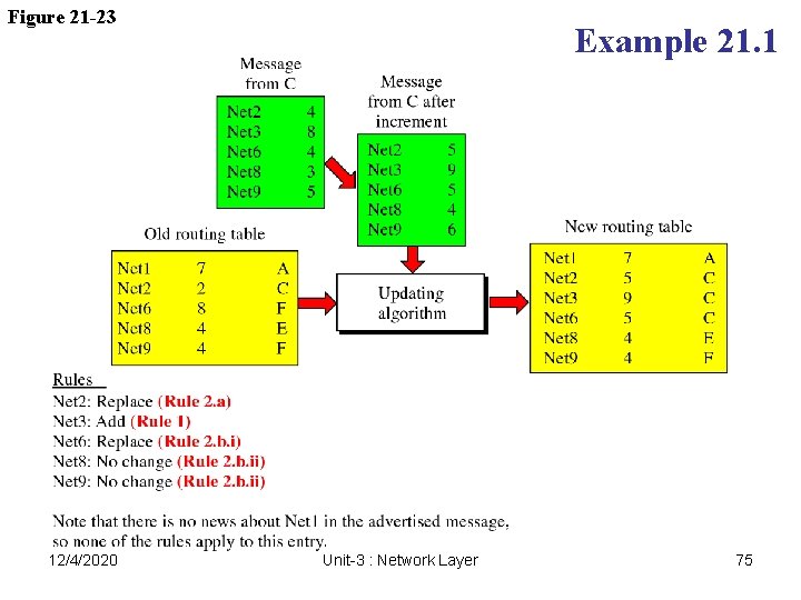
Figure 21 -23 12/4/2020 Example 21. 1 Unit-3 : Network Layer 75
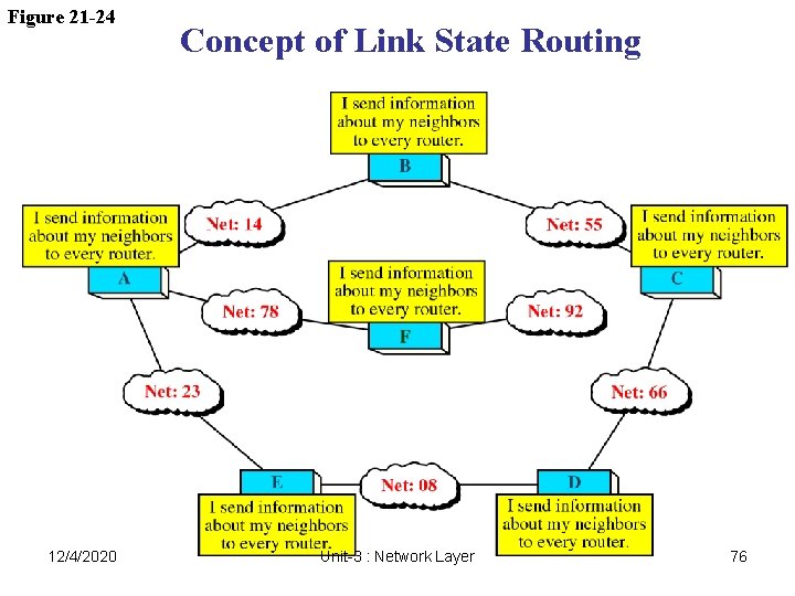
Figure 21 -24 12/4/2020 Concept of Link State Routing Unit-3 : Network Layer 76
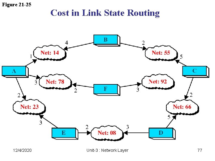
Figure 21 -25 12/4/2020 Cost in Link State Routing Unit-3 : Network Layer 77
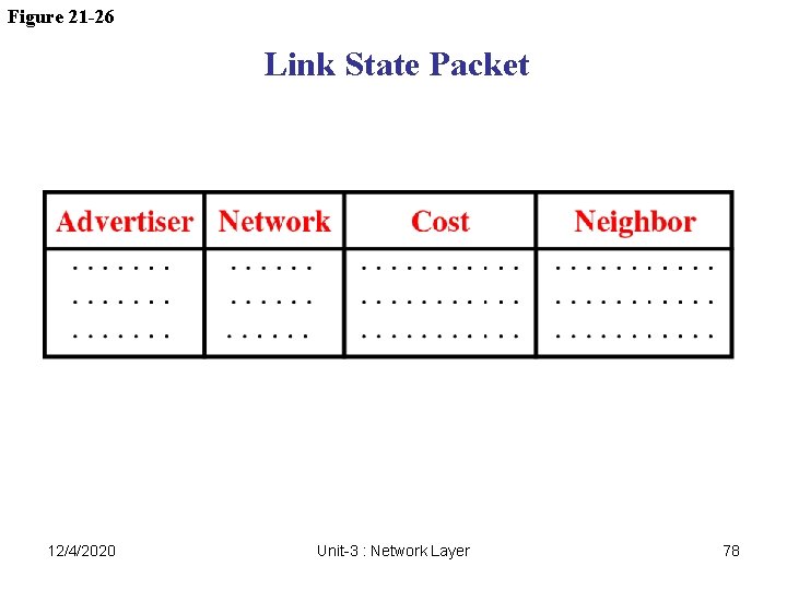
Figure 21 -26 Link State Packet 12/4/2020 Unit-3 : Network Layer 78
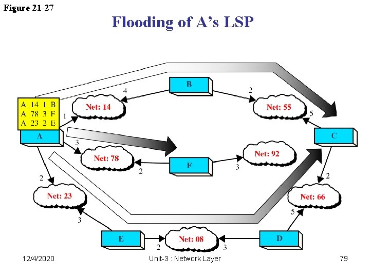
Figure 21 -27 12/4/2020 Flooding of A’s LSP Unit-3 : Network Layer 79
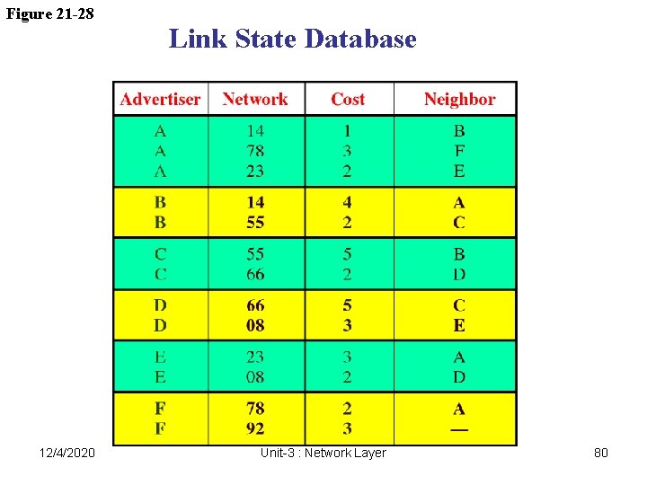
Figure 21 -28 12/4/2020 Link State Database Unit-3 : Network Layer 80
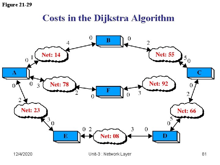
Figure 21 -29 Costs in the Dijkstra Algorithm 12/4/2020 Unit-3 : Network Layer 81
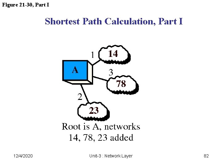
Figure 21 -30, Part I Shortest Path Calculation, Part I 12/4/2020 Unit-3 : Network Layer 82
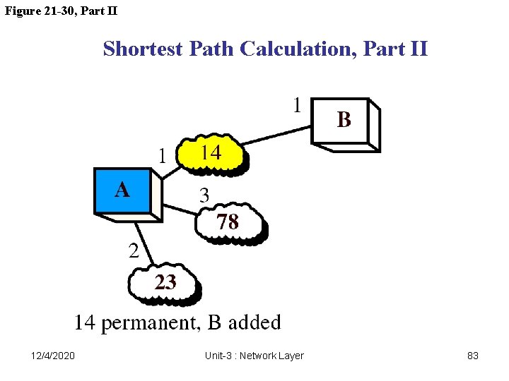
Figure 21 -30, Part II Shortest Path Calculation, Part II 12/4/2020 Unit-3 : Network Layer 83
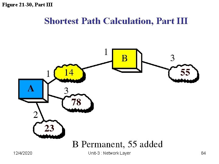
Figure 21 -30, Part III Shortest Path Calculation, Part III 12/4/2020 Unit-3 : Network Layer 84
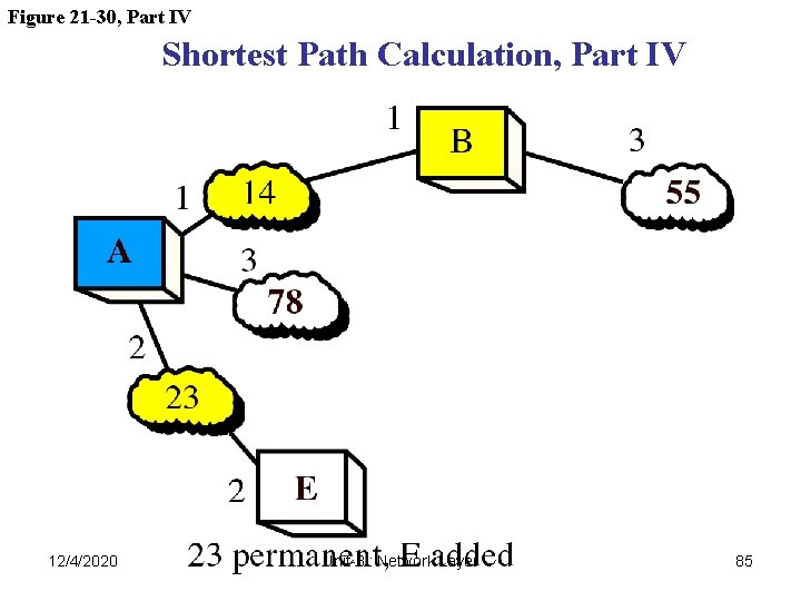
Figure 21 -30, Part IV Shortest Path Calculation, Part IV 12/4/2020 Unit-3 : Network Layer 85
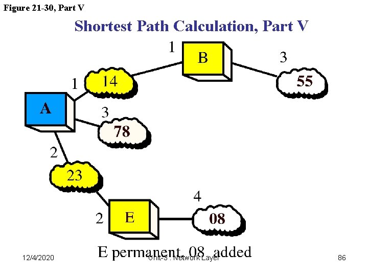
Figure 21 -30, Part V Shortest Path Calculation, Part V 12/4/2020 Unit-3 : Network Layer 86
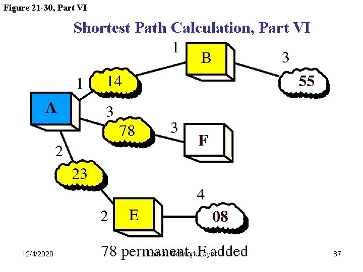
Figure 21 -30, Part VI Shortest Path Calculation, Part VI 12/4/2020 Unit-3 : Network Layer 87
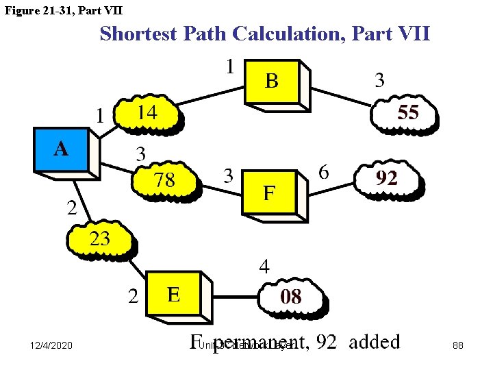
Figure 21 -31, Part VII Shortest Path Calculation, Part VII 12/4/2020 Unit-3 : Network Layer 88
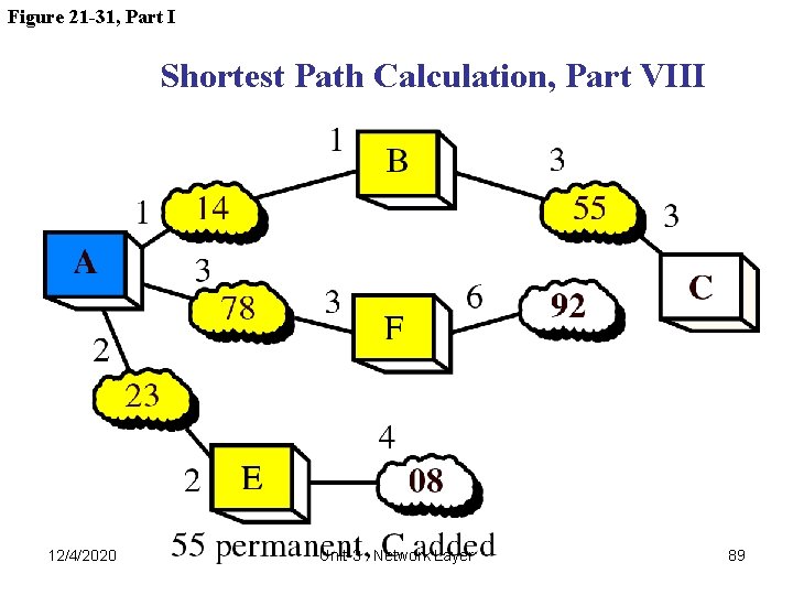
Figure 21 -31, Part I Shortest Path Calculation, Part VIII 12/4/2020 Unit-3 : Network Layer 89
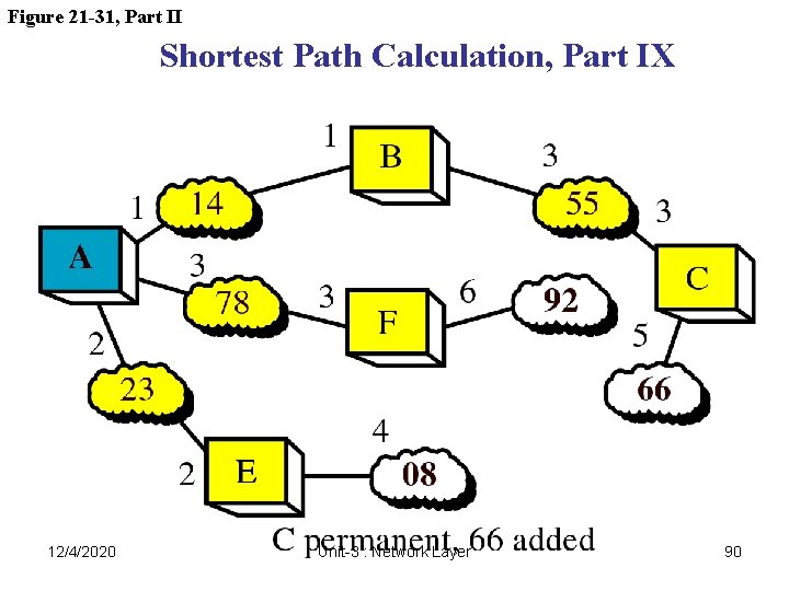
Figure 21 -31, Part II Shortest Path Calculation, Part IX 12/4/2020 Unit-3 : Network Layer 90
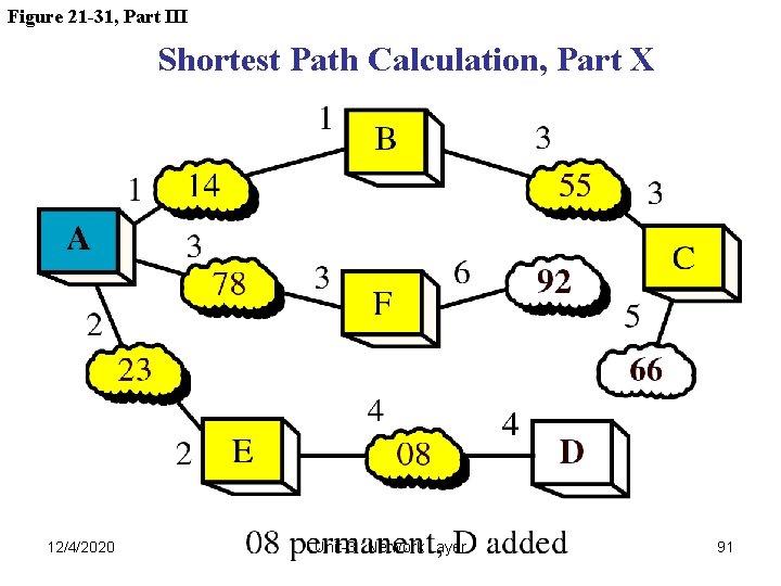
Figure 21 -31, Part III Shortest Path Calculation, Part X 12/4/2020 Unit-3 : Network Layer 91
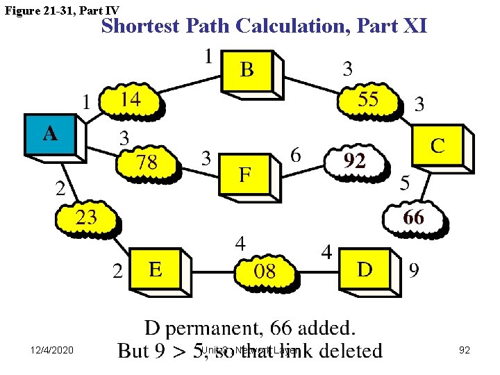
Figure 21 -31, Part IV Shortest Path Calculation, Part XI 12/4/2020 Unit-3 : Network Layer 92
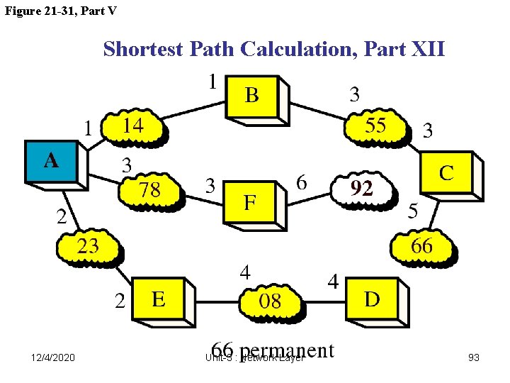
Figure 21 -31, Part V Shortest Path Calculation, Part XII 12/4/2020 Unit-3 : Network Layer 93
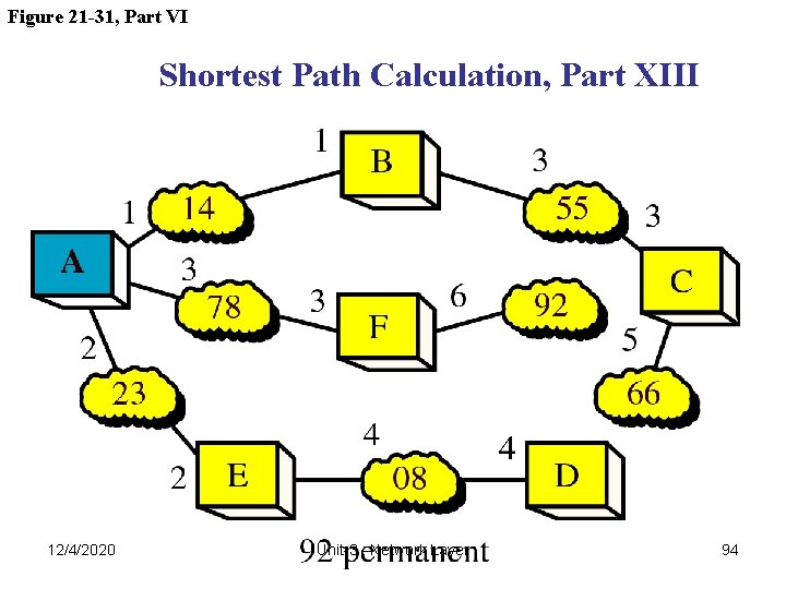
Figure 21 -31, Part VI Shortest Path Calculation, Part XIII 12/4/2020 Unit-3 : Network Layer 94
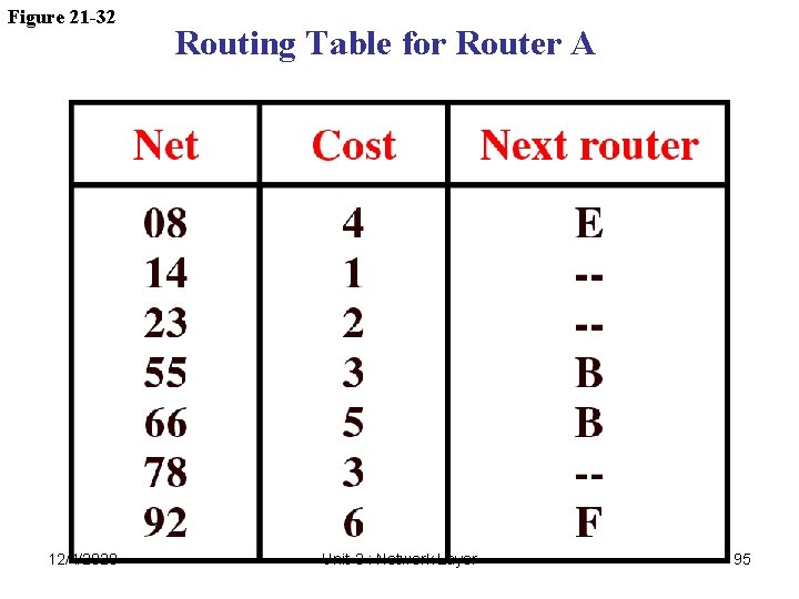
Figure 21 -32 12/4/2020 Routing Table for Router A Unit-3 : Network Layer 95