Business System Development CSC 581 Lecture 31 Course

Business System Development CSC 581

Lecture 31 Course Revision

Introduction n Information Systems Analysis and Design l Complex organizational process whereby computerbased information systems are developed and maintained n Application Software l Computer software designed to support organizational functions or processes n Systems Analyst l Organizational role most responsible for analysis and design of information systems
")
Introduction (cont. )

A Modern Approach to Systems Analysis and Design n 1950 s: focus on efficient automation of existing n n n processes 1960 s: advent of 3 GL, faster and more reliable computers 1970 s: system development becomes more like an engineering discipline 1980 s: major breakthrough with 4 GL, CASE tools, object oriented methods 1990 s: focus on system integration, GUI applications, client/server platforms, Internet The new century: Web application development, wireless PDAs, component-based applications
 Automate handling")
Types of Information Systems and Systems Development n Transaction Processing Systems (TPS) Automate handling of data about business activities (transactions) l Process orientation l n Management Information Systems (MIS) Converts raw data from transaction processing system into meaningful form l Data orientation l n Decision Support Systems (DSS) Designed to help decision makers l Provides interactive environment for decision making l Involves data warehouses, executive information systems (EIS) l Database, model base, user dialogue l
")
Types of Information Systems and Systems Development (cont. )
 n Traditional methodology for developing, maintaining, and replacing information")
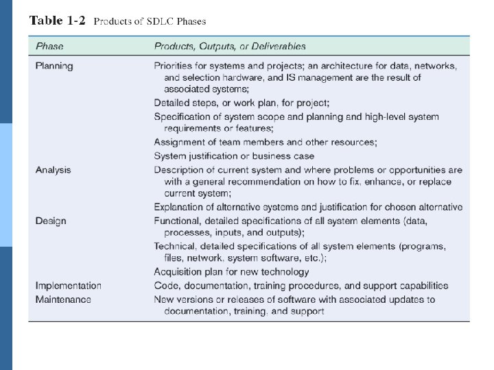
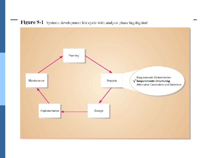
Systems Development Life Cycle (SDLC) n Traditional methodology for developing, maintaining, and replacing information systems n Phases in SDLC: l Planning l Analysis l Design l Implementation l Maintenance

SDLC Planning Phase Identify, analyze, prioritize, and arrange IS needs

SDLC Analysis Phase Study and structure system requirements

SDLC Design Phase Convert recommended solution to system specifications Logical design: functional features described independently of computer platform Physical design: logical specifications transformed to technologyspecific details

SDLC Implementation Phase Code, test, install, and support the information system

SDLC Maintenance Phase Systematically repair and improve the information system

Traditional Waterfall SDLC One phase begins when another completes, little backtracking and looping
")
Problems with Waterfall Approach n System requirements “locked in” after being determined (can't change) n Limited user involvement (only in requirements phase) n Too much focus on milestone deadlines of SDLC phases to the detriment of sound development practices

Alternatives to Traditional Waterfall SDLC n Prototyping n CASE tools n Joint Application Design (JAD) n Rapid Application Development (RAD) n Agile Methodologies n e. Xtreme Programming

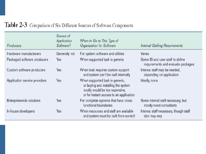
Sources of Application Software

Hardware Manufacturers n IBM is the leader in software sales and services. n Hardware manufacturers tend to focus on system software and utilities.

Packaged Software Producers n Microsoft is the leader in prepackaged software production. n Prepackaged software is off-the-shelf software. n Often, prepackaged software is turnkey software (i. e. not customizable).

Custom Software Producers n Firms like Accenture and EDS are leading custom software producers. n Consulting firms develop software to meet the client’s specific requirements. n Consulting firms are usually called when the client company does not have in-house expertise or manpower available to develop the system.
 systems that integrate individual traditional business")
Enterprise Solutions Software n Enterprise Resource Planning (ERP) systems that integrate individual traditional business functions into modules enabling a single seamless transaction to cut across functional boundaries. n SAP AG is the leading vendor of ERP systems.

Application Service Providers n ASP: an organization that hosts and runs computer applications for other companies, typically on a per-use or license basis

In-House Development n If sufficient system development expertise with the chosen platform exists in-house, then some or all of the system can be developed by the organization’s own staff. n Often, there a variety of sources used, with in-house staff playing a role as well as consultants or ERP vendors.

Managing the Information Systems Project n Project l A planned undertaking of related activities to reach an objective that has a beginning and an end n Project management l A controlled process of initiating, planning, executing, and closing down a project
 n Project manager l Systems analyst with")
Managing the Information Systems Project (cont. ) n Project manager l Systems analyst with management and leadership skills responsible for leading project initiation, planning, execution, and closedown n Deliverable l The end product of an SDLC phase

Project Management Activities

Phases of Project Management Process n Phase 1: Initiation n Phase 2: Planning n Phase 3: Execution n Phase 4: Closedown

PM Phase 1: Project Initiation n Assess size, scope and complexity, and establish procedures. n Establish: l Initiation team l Relationship with customer l Project initiation plan l Management procedures l Project management environment l Project workbook

PM Phase 2: Project Planning n Define clear, discrete activities and the work needed to complete each activity n Tasks l Define project scope, alternatives, feasibility l Divide project into tasks l Estimate resource requirements l Develop preliminary schedule l Develop communication plan l Determine standards and procedures l Risk identification and assessment l Create preliminary budget l Develop a statement of work l Set baseline project plan

PM Phase 3: Project Execution n Plans created in prior phases are put into action. n Actions l l l Execute baseline project plan Monitor progress against baseline plan Manage changes in baseline plan Maintain project workbook Communicate project status

PM Phase 4: Project Closedown n Bring the project to an end. n Actions l Close down the project. l Conduct post-project reviews. l Close the customer contract.

Project Identification Tasks n Identifying potential development projects l Identification from a stakeholder group n Classifying and ranking potential IS projects l Using value chain analysis or other evaluation criteria n Selecting projects l Based on various factors

Each stakeholder group brings their own perspective and motivation to the IS decision.

Value chain analysis: analyzing an organization's activities to determine where value is added to products/services and the costs incurred for doing so.

Factors for Project Selection

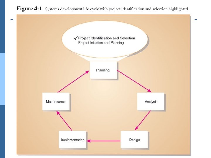
Project Initiation and Planning

Project Initiation Tasks n Establish: l Initiation team l Relationship with customer l Project initiation plan l Management procedures l Project management environment l Project workbook

Project Planning Tasks n Describe project scope, alternatives, feasibility. n Divide project into tasks. n Estimate resource requirements and create resource n n n n plan. Develop preliminary schedule. Develop communication plan. Determine standards and procedures. Identify and assess risk. Create preliminary budget. Develop a statement of work. Set baseline project plan.

Deliverables and Outcomes n Business Case l Justification for an information system, expressed as tangible and intangible costs and benefits, and technical/organizational feasibility n Baseline Project Plan (BPP) n Statement of Work (SOW)

System Requirements Determination

Characteristics for Successful Requirements Determination n Impertinence n Impartiality n Relaxing constraints n Attention to details n Reframing

Deliverables of Requirements Determination n From interviews and observations l Interview transcripts, observation notes, meeting minutes n From existing written documents l Mission and strategy statements, business forms, procedure manuals, job descriptions, training manuals, system documentation, flowcharts n From computerized sources l JAD session results, CASE repositories, system prototype displays and reports

Traditional Requirements Determination Methods n Interviewing individuals n Interviewing groups n Observing workers n Studying business documents

Process Modeling n Graphically represent the processes that capture, manipulate, store, and distribute data between a system and its environment and among system components n Utilize information gathered during requirements determination n Processes and data structures are modeled
 Deliverables and Outcomes n Context data flow diagram (DFD) l")
Process Modeling (cont. ) Deliverables and Outcomes n Context data flow diagram (DFD) l Scope of system n DFDs of current physical and logical system l Enables analysts to understand current system n DFDs of new logical system Technology independent l Show data flows, structure, and functional requirements of new system l n Thorough description of each DFD component

DFD Levels n Context DFD l Overview of the organizational system n Level-0 DFD l Representation of system’s major processes at high level of abstraction n Level-1 DFD l Results from decomposition of Level 0 diagram n Level-n DFD l Results from decomposition of Level n-1 diagram

Context Diagram Context diagram shows the system boundaries, external entities that interact with the system, and major information flows between entities and the system. NOTE: only one process symbol, and no data stores shown.

Level-0 DFD shows the system’s major processes, data flows, and data stores at a high level of abstraction. Processes are labeled 1. 0, 2. 0, etc. These will be decomposed into more primitive (lower-level) DFDs.

Level-1 DFD shows the subprocesses of one of the processes in the Level-0 DFD. This is a Level-1 DFD for Process 4. 0. Processes are labeled 4. 1, 4. 2, etc. These can be further decomposed in more primitive (lower-level) DFDs if necessary.
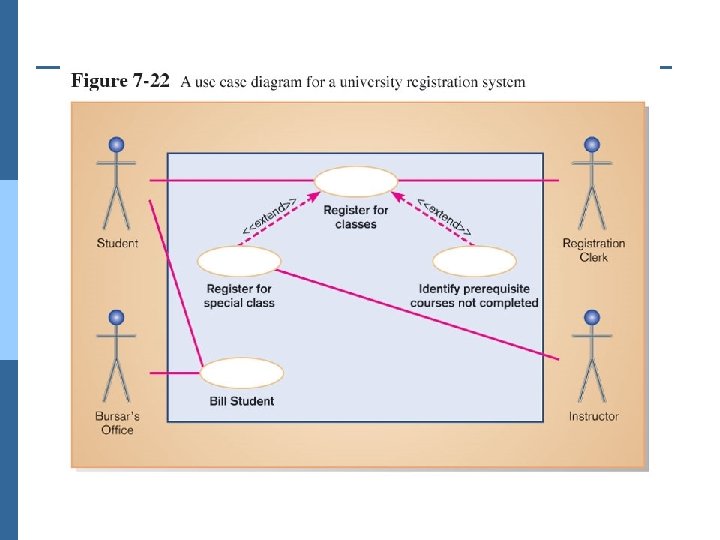

What is an <<include>> Relationship? n A connection between two use cases n Indicates a use case that is used (invoked) by another use case n Links to general purpose functions, used by many other use cases

Modeling Logic n Structured English n Decision Tables n Decision Trees

Decision Table Note: for salaried employees the action stub chosen will always be the same…therefore hours worked is an indifferent condition

Reduced Decision Table Because of indifferent condition, the complete decision table can be reduced to one with fewer rules

Decision tree representation of salary decision

Alternative decision tree representation of salary decision

Deciding Among Structured English, Decision Tables, and Decision Trees Criteria Structured Decision English Tables Decision Trees Determining Second Best Conditions and Actions Third Best Transforming Best Conditions and Actions into Sequence Third Best Checking Consistency and Completeness Best Third Best

Deciding Between Decision Tables and Decision Trees Criteria Decision Tables Decision Trees Portraying complex logic Best Worst Portraying simple Worst rules Best Making decisions Worst Best More compact Best Worst Easier to manipulate Best Worst
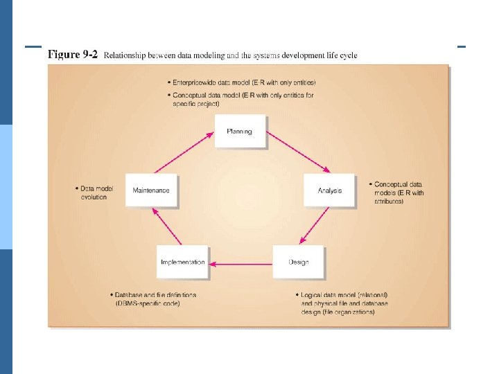

Conceptual Data Modeling n A detailed model that captures the overall structure of data in an organization n Independent of any database management system (DBMS) or other implementation considerations

Process of Conceptual Data Modeling n Develop a data model for the current system n Develop a new conceptual data model that includes all requirements of the new system n In the design stage, the conceptual data model is translated into a physical design n Project repository links all design and data modeling steps performed during SDLC
 diagram or class")
Deliverables and Outcome n Primary deliverable is an entity-relationship (E -R) diagram or class diagram n As many as 4 E-R or class diagrams are produced analyzed E-R diagram that covers data needed in the project’s application l E-R diagram for the application being replaced l E-R diagram for the whole database from which the new application’s data are extracted l E-R diagram for the whole database from which data for the application system being replaced is drawn l
 n Second deliverable is a set of entries about")
Deliverables and Outcome (cont. ) n Second deliverable is a set of entries about data objects to be stored in repository or project dictionary. l Repository links data, process, and logic models of an information system. l Data elements included in the DFD must appear in the data model and vice versa. l Each data store in a process model must relate to business objects represented in the data model.

The Object-Oriented Development Life Cycle n Process of progressively developing representation of a system component (or object) through the phases of analysis, design, and implementation n The model is abstract in the early stages n As the model evolves, it becomes more and more detailed

Object oriented cycle is like an onion, evolving from abstract to detailed, from external qualities to system architecture and algorithms.

Object-Oriented Deliverables and Outcomes 1. 2. 3. 4. 5. 6. 7. The ability to tackle more challenging problem domains Improved communication among users, analysts, designers, and programmers Increased consistency among analysis, design, and programming activities Explicit representation of commonality among system components Robust systems Reusability of analysis, design, and programming results Increased consistency among the models developed during object-oriented analysis, design, and programming

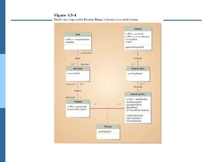
Class Diagrams Revisited n Features: l Objects and classes l Encapsulation of attributes and operations l Polymorphism l Inheritance l Aggregation and composition

Dynamic Modeling n Representation of activities that occur throughout the lifetime of a system n Types of UML dynamic models l State diagram: state changes within an object l Sequence diagram: time-sequenced interactions between objects l Activity diagram: flow of control between activities within an object

Guard condition Action Guard condition A transition is labeled with a guard condition and/or an action, separated with a forward slash / State diagram: a model of the states of a single object and the events that cause the object to change from one state to another

object lifeline message time activation

Process Modeling: Activity Diagrams n Shows the conditional logic for the sequence of system activities needed to accomplish a business process n Clearly shows parallel and alternative behaviors n Can be used to show the logic of a use case

branch activity synchronization bar swimlane

The End
- Slides: 78