Switching System Switching systems Analogue type of switching


 hops is rather simple")


 Each")
- Slides: 79
Switching System
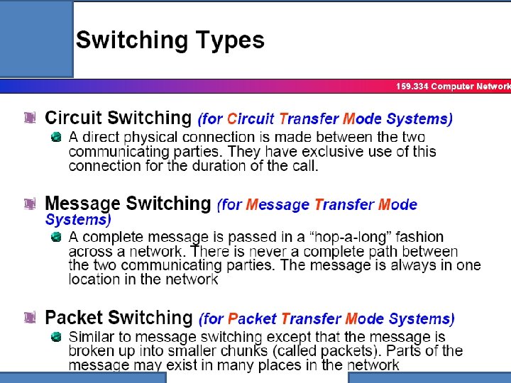
Switching systems • • • Analogue type of switching Multistage analogue switches Digital type of switch Packet switch Comparision of circuit, message & packet switches
ANALOGUE TYPE OF SWITCHING • CAN SEE ALL THE VOLTAGES W. R. TO TIME IN THE SWITCHING NETWORK • NO OF CROSS POINTS, AVALABILITY, BLOCKING • NO OF CROSS POINTS ARE ANALOGUES TO COST • AVALABILITY MEANS ANY INPUT CAN REACH ANY OUTPUTS • BLOCKING MEANS, WHEN THE SWITCHING NETWORK IS ALREADY LOADED, IF YOU CAN FURTHER CONNECT AN FREE INPUT TO A FREE OUTPUT, IT IS SAID TO BE NON BLOCKING.
Basic analogue switch Output C Analogy D C A B A A B B Input No of points =4 Full available Switch Non blocking switch All the voltages generated in the phone can be seen in the points D C D
4 4 switching 16 No: of * points = Is it fully available = Yes Is it non-blocking = Yes When the number of inputs and no: of ouptuts increases , we have to think about a alternative solution
QUALITY FACTORS OF A SWITCHING NETWORK A B E F C D G H To have full availability, we should have at least 1 link from the input small switch to a small output switch as shown above Blocking: A B C D How to make this non-blocking? E F G H A B C D When A is connected to E, can B be connected to F? No, therefore this is a blocking network E F 2 2 G H
2 stage Link switching networks full available but blocking. How to make non blocking
2 stage Link switching networks full available and non blocking. 3 3 3 3 3
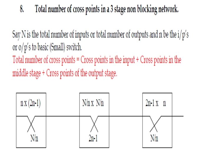
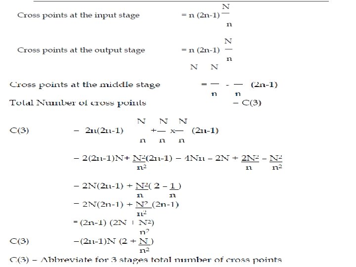
ANALYSIS OF 3 stage link switching networks for non blocking
ANALYSIS OF 3 stage link switching networks for non blocking 1 2 2 1
Non-blocking 3 stage switching network
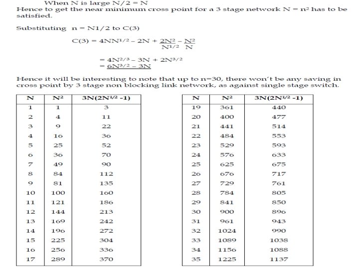
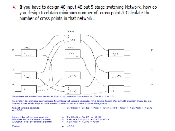
Near minimum cross points
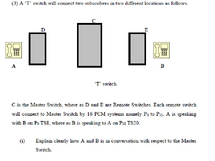
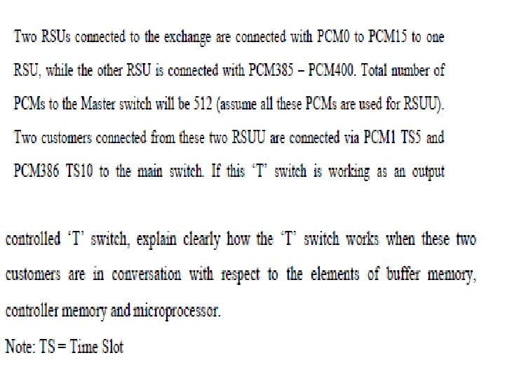
Working of T switch Assume a master switch is connected with 2 RSU’s A B
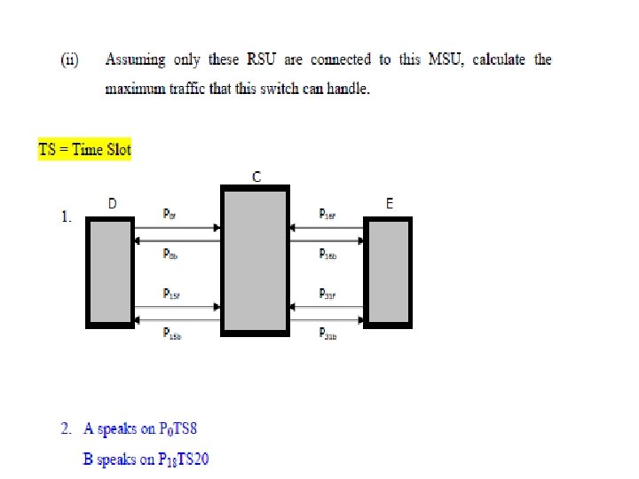
Working of T switch Assume a master switch is connected with 2 RSU’s as shown in the figure below Assume 16 PCm systems are connetcted to from RSU to MSU B A Now assume that A is speaking with B A speaks in p 1 TS 5 and B in p 16 TS 10 What will happen at the master switch C ? Switching Equation A’s hello !! P 1 f TS 5 ------- P 16 b TS 10 B’s hello !! P 16 f TS 10 --- P 1 b TS 5 B will hear. A will hear.
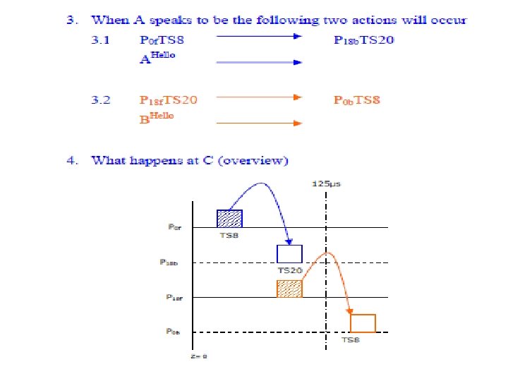
Detailed working of T-switch Timing chart A’s hello !! P 1 f TS 5 B’s hello !! P 16 f. TS 10 P 1 f ------ P 16 b TS 10 B will hear. ---- P 1 b TS 5 A will hear. TS 5 P 16 b TS 10 P 16 f TS 10 P 1 b TS 5 T=0 T=125µs
What really happens at the T-switch A’s hello !! B’s hello !! P 1 f TS 5 P 16 f. TS 10 ------ P 16 b TS 10 ---- P 1 b TS 5 B will hear. A will hear. 4 4 2 W 0 P 1 f TS 5 1 1 P 16 f TS 10 W 5 3 W 522 2 Go to W 522 W 0 W 5 Go to W 522 3 W 1023 8 Bits Buffer Memory Microprocessor-2 actions for each channel in 125µs W 1023 10 Bits Control Memory
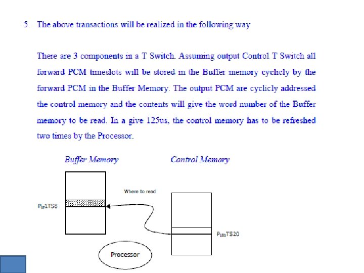
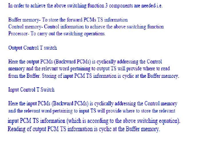
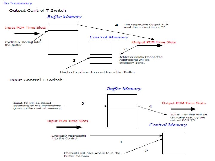
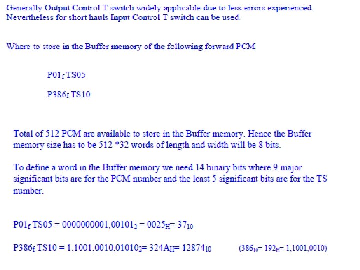
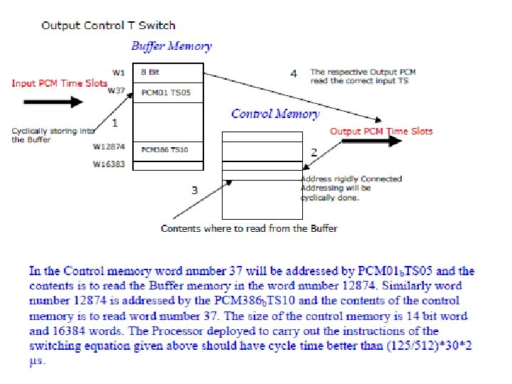
TYPES OF T SWITCHES • WHAT WE HAHE STUDIED NOW IS OUTPUT CONTROLLED T SWITCH • THE INPUT PCM TSS ARE CYLICLY STORE IN THE BUFFER MEMORY • THE OUT PCM ARE CYCLICLY ADDRESSING THE CONTROLLED MEMORY, THE CONTENTS WILL TELL YOU WHERE TO READ AND TRANSPORT IT TO THE DESTINATION. • THE OUTPUT PCMS ARE RIGIDLY CONNECTED TO THE CONTROLED MEM, ORY THATS WHY IT IS CALLED OUT PUT CONTROLLED T SWITCH • SIMILARLY CAN YOU TRY A INPUT CONTROLLED T SWICH AND WRITE ITS CHARACTERISTICS?
CHARACTERISTICS OF INPUT CONTROLLED T SWITCH • INPUT PCMS ARE RIGIDLY CONNECTED TO THE CONNTROLLED MEMORY • THE INPUT PCMS ARE CYCLICLY ADDRESSING THE CONTROLLED MEMORY. THE CONTENTS WILL TELL YOU WHER TO STORE IN THE BUFFER MEMORY. • THE OUTPUT PCMS ARE CYCLICLY READING THE BUFFER MEMORY.
BASIC COMPONANTS OF A SWITCHING SYSTEM • • SWITCHING UNIT CONTROLLED UNIT PERIPARALS SOFTWARE • IS IT ANALOGUES TO HUMAN BODY? • YES, EXCEPT FREE WILL OF THE HUMAN, THIS SYSTEM WILL HAVE HEART, BRAIN & MIND
Comparison of Human with Animal & SWITCHING NODE HUMAN HEART BRAIN MIND TRUTH FREE WILL/GOOD TELEPHOE NODE SWITCHING NETWORK CONTROL NETWORK SOFTWARE PROGRAMMING ANIMAL HEART BRAIN INSTINC
SWITCHING UNIT • MAIN FUNCTION—connecting to an input to a output • In the case of local node, input will be the customer, and the output will be a route, where the call is destined to • Limiting factor: no of connections that can be established simultaneously is the limiting factor • MEASURED IN ERLANG • Present day technology : analogue & digital switches are now obsolete, now packet switching routers are deployed.
CONTROLLED UNIT • FUNCTION: ALL THE MANAGEMENT FUNCTIONS THAT NEED TO CARRYOUT IN ESTABLISHING ACONNECTION WILL BE DONE BY THE CONTROLLED UNIT. • THE MANAGEMENT FUNCTIONS ARE /CALL ESTABLISHMENT, SENDING INFORMATION TO THE OTHER NODES, CALL BILLING FUNCTION, CUSTOMER FACCILITY MANAGEMENT ETC. . . • LIMITATION WILL BE THE OCCUPANCY OF THE PROCESSOR. NORMALLY MORE THAN 80% WILL NOT BE ADVISABLE FOR ANY PROCESSOR. ANOTHER MEASUREMENT WILL BE TLME TAKEN TO ESTABLISH A CONNECTION • TECHNOLOGY: CENTRALISED CONTROL FUNCTION HAS BEEN SHIFTED TO DITRIBUTED PROCESSER FUNCTION. MODERN NGN SWITCH WILL HAVE MOST OF THE MANAGEMENT FUNTIONS CENTRALISED TO THE CONTROL PART OF SOFT SWITCH, WHILE ROUTING PART IS DISTRIBUTED TO THE ROUTERS. ANOLGUE CONTROL(WIRED LGIC), IS OBSELETE.
PERIPARALS • THEY ARE THE ANCILIARY EQUIPMENT TO CARRY OUT THE MAJOR FUNTIONALITIES OF THE SYSTEM. THEY BARE REGISTERS, TONE GENERETORS, TIMING DEVICES, ETC. . .
SOFTWARE • SOFTWARE WILL PROVIDE ALL DETAILED ACTION PLANS IS BECOMING HIGLY COMPLEX. • MODULAR KIND OF SOFTWARE IS NOW ENCOURAGED. • WITH NGN TECHNOLOGY THE SOFTWARE HAS BECOME A VITAL ELEMENT FOR THE PROPER FUNCTIONING OF MUTIPLE SERVICE FACILIETIES.
Understanding traffic concepts
v
Packet Switching
THE IP WORLD • TODAY WE ARE IN THE IP WORLD • ALL THE NETWORKS ARE PUSHING TO THE IP APPLICATIONS • MODERN CODING METHODS PUSH IP NETWORKS TO GO FOR REAL TIME APPLICATIONS • TDM & ATM NETWORKS ARE REPLACED BY IP • LETS STUDY THE PACKET CONCEPTS
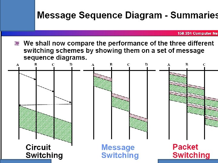
Major switching types Circuit , Message and Packet switching
CHRACTERISTICS OF SIGNALLING & VOICE • CHANNEL ASSOCIATED SIGNALLING & VOICE IN ONE TUNNEL-WASTAGE IN SIGNALLING, AND LESS THAN 50% EFFICIENT IN VOICE MEDIA DUE TO THE CHARACTERISTICS OF VOICE. COMMON CHANNEL SIGNALLING IS COMMONLY USED FOR MANY VOICE CHANNELS, HENCE SIGNALLING CHANNEL IS EFFICIENT. VOIE CHANNELS CARRIES THE SAME INEFFICIENCY AS IN THE CASE OF CHANNEL ASSOCIATED SIGNALLING HENCE THE CONCEPTS OF MESSAGE AND PACKET SWITCHING NETWORK TO BE CONSIDERED.
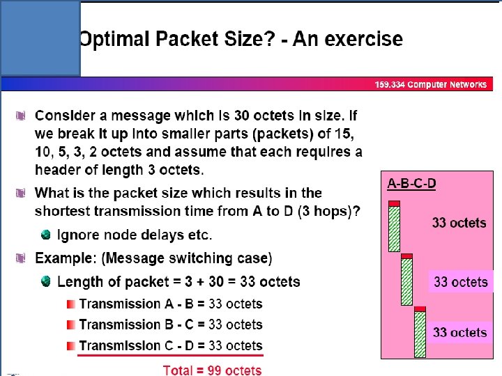
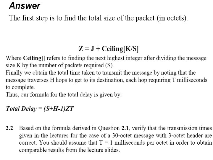
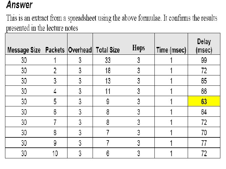
DELAY ANALYSIS OF A MESSAGE SWITCH • TAKE THE PREVIOUS EXAMPLE, THE FOLLOWING ARE KNOWN • MESSAGE SIZE=30, OVERHEAD=3, NO OF HOPS=3, THE DELAY FOR ONE HOP/OCTET=1 MSEC. • THE TOTAL DELAY FOR 3 HOPS=33*3 MSEC • TOTAL DELAY=NO OF HOPS*NO OF OCTET IN MESSAGE+NO OF OVERHEAD OCTETS IN THE MESSAGE(THIS RESULT IS TALLYING)
Deciding Optimum Packet Size Packet 1 l MESSAGE Packet 2 Packet 3 l l. • Shown above is a message • The message will be divided in to equal length packets • Each Packet will have a Header The header will consist the following details: – Originating Point Code – Terminating Point Code – Packet Number Packet 1
A B C D Packet 1 Packet 2 Packet 1 Packet 3 Packet 2 Packet 3 T 1 Packet 2 Time Slots How Many Transactio ns? T 2 1 T 3 2 3 Packet 3 T 4 2 T 5 TOTAL DELAY α S + H - 1 Where S - Number of Packets H - Number of Hops Therefore in this case the total delay time is α 3 + 3 – 1 = 5 1
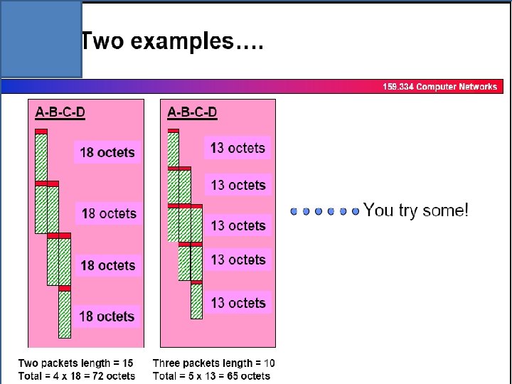
DELAY ANALYSIS FOR PACKET SWITCHING NETWORK • TAKE TWO EXAMPLES THE 30 OCTET MESSAGE IS (1) MADE TO TWO PACKETS OF 15 OCTET EACH, (2) MADE TO 3 PACKETS OF 10 OCTETS EACH • YOU WILL OBSERVE THE FOLLOWING OVERLAP SENDING OF PACKETS, FOR EXAMPLE, WHEN 1 ST PACKET RCEIVED AT B, THIS PACKET IS SEND FROM B TO C, DURING THIS TIME THE 2 ND PACKET IS SEND FROM A TO B. NOTE THAT IN AGIVEN TIME 2 ACTIONS HAVE BEEN MADE THE TOTAL DELAY EXPERIENCED IN (1)72 MSEC (2) 65 MSEC
Message vs Packet delay • It is easy to calculate message delay rather than packet delay , why ? • When sending packets from one node to another the following process can be adopted as against message transmission • (a)Packets can be sent to another node through different paths simultaneously • (b)Packetizing at the node and sending packets over the hop can be made in different times to maximize the sending of packets over a hop. • (C)Hence , overlap sending & receiving of packets can be achieved in a node. Hence the delay introduced in packet mode is rather complicated (than message) although it is efficient.
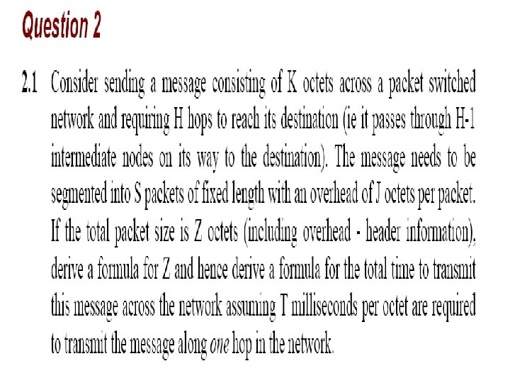
Contd…. • In message mode the delay introduced in (H-1) hops is rather simple and is equal to • Message delay = K * (H-1) • In packet mode the delay is proportional to addition delay to message length and it is assumed to be • D = K*(H-1) + term proportional to message length • Delay={ S+ (H-1) } * ZT
Summary
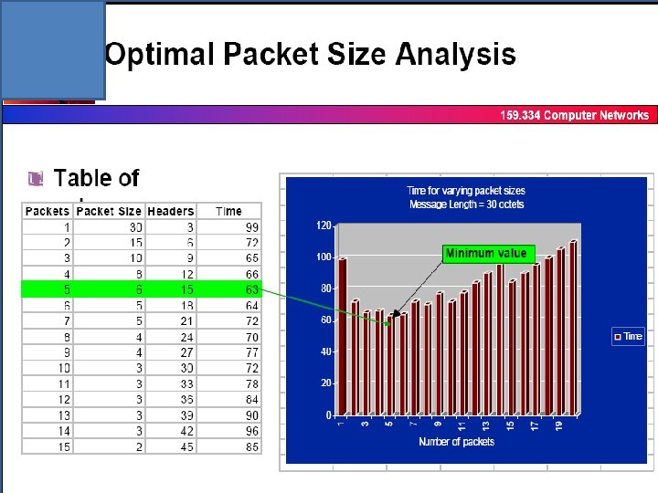
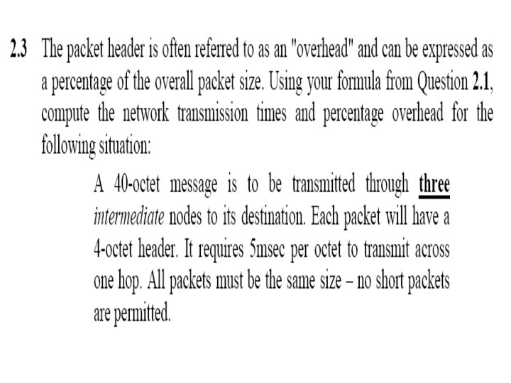
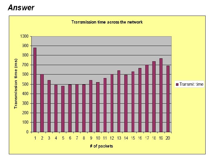
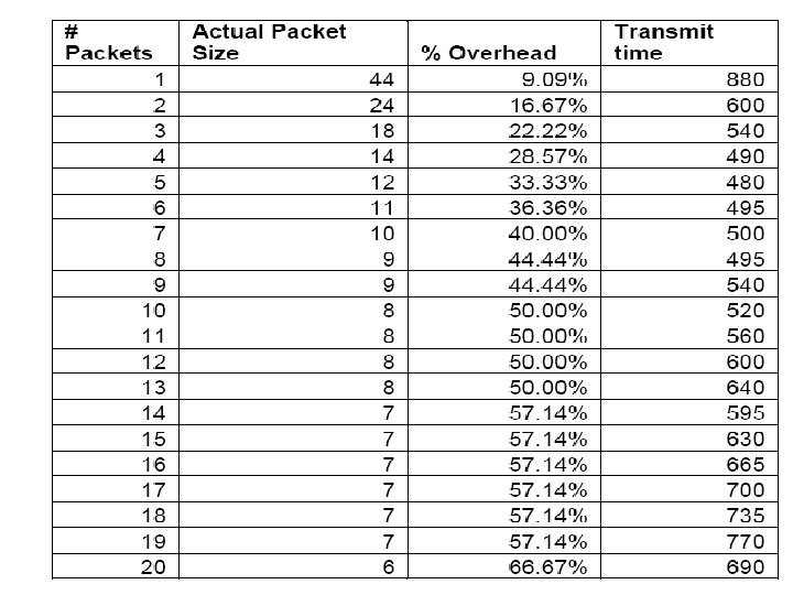
Calculation of the optimum packet size • Deciding the optimum packet size will depend upon 2 factors • Overall delay • Overall overhead bits compared to the message • Calculate the optimum packet size of 30 octet message, where the overhead for aq packet is 3 octet?
What is the packet network? • A packet is a unit of data that is transmitted across a packet -switched network. • A packet-switched network is an interconnected set of networks that are joined by routers or switching routers.
Example • Packet Switching technology TCP/IP • largest packet-switched network Internet
Why ? • Data traffic is bursty – Logging in to remote machines – Exchanging e-mail messages • Don’t want to waste reserved bandwidth – No traffic exchanged during idle periods • Better to allow multiplexing – Different transfers share access to same links
Goals • To optimize utilization of available link capacity • To increase the robustness of communication
Concept • A method of transmitting messages through a communication network, in which long messages are subdivided into short packets. • The packets are then sent through the network to the destination node.
Packet-Switching Techniques Datagram Each packet contains addressing information and is routed separately Virtual Circuits A logical connection is established before any packets are sent; packets follow the same route.
Datagram • • • Each packet treated independently Packets can take any practical route Packets may arrive out of order Packets may go missing Up to receiver to re-order packets and recover from missing packets
Computer A 1 2 3 Need to transmit ‘ 123’ from computer A to computer B First data is broken to small pieces (PACKETS) Computer B
Computer A 3 Routers in the network read this address and forward packets along the most appropriate path to that destination. 1 2 Packets contain header information that includes a destination address. Computer B
Computer A 2 1 3 Computer B
Computer A 2 1 3 Computer B
Computer A 2 1 3 Computer B
Virtual Circuits v Datagram • Virtual circuits – Network can provide sequencing and error control – Packets are forwarded more quickly • No routing decisions to make – Less reliable • Loss of a node loses all circuits through that node • Datagram – No call setup phase • Better if few packets – More flexible • Routing can be used to avoid congested parts of the network
Advantages • Line efficiency – Single node to node link can be shared by many packets over time – Packets queued and transmitted as fast as possible • Data rate conversion – Each station connects to the local node at its own speed – Nodes buffer data if required to equalize rates • Packets are accepted even when network is busy – Delivery may slow down • Priorities can be used
Difference between channel associated common channel and packet signaling networks Channel associated signalling(CAS) Each voice channel will have a supervisory channel(either direct or associate). Highly inefficient for the signalling channel and less than 50% efficient for the voice channel. Common Channel signalling – All supervisory Signals of voice channels are in one time slot And the voice channels have similar inefficiency as CAS Voice channel Supervisor signal Signalling and voice are going on packets whenever it is needed Packet network=Signalling and voice are sent in packets , highly efficient for voice as well as signalling. The deficiecy experienced for voice channels, in CAS & CCS has overcome