UNIT II compression molds 1 2 3 4


")


 To maintain balance where transfer moulds employ an")


- Slides: 89
UNIT- II compression molds 1 2 3 4 Classification of compression molds Factors that moulding, influence thermoset Materials selection in relation to moulding conditions Design of Mould Cavity - 5 Calculation related to-Number of Cavities, Clamping force, shot weight 6 Design of Rotational mould, 7 advantages and disadvantages compression molds of 3. 4 1. What do you mean by landed positive mould 2. Gassing or breathing the mould is necessary in compression moulding. Justify (2005) 3. What do you mean by sub cavity mould? Explain 4. With neat diagrams, explain the two types of moulds used in compression moulding. (8) (2005 3. 16 1. Discuss the factors that influence compression moulding 2. Explain the factors which influence thermoset moulding process. (8) (2005 discuss the Materials selection in relation to moulding conditions 3. 13 write the clamping force for compression mould 3. 23 discuss the advantages and disadvantages of compression mold
8 9 10 11 12 13 14 Transfer molding- types, principles Design of pots and plunger, Feed system Economic determination of the no. of cavity and Technological Determination of the no of cavity Design of mould cavity and Design of load chamber Transfer tonnage, shot weight. Heat losses and energy requirement to heat the mould Advantage and disadvantage of T/M Tutorial venting comparison C/M and T/M Bulk factor 4. 15 1. Discuss the principles involved in transfer moulding. Briefly explain different types of transfer moulding (16) (2005) 2. discuss the design of pot and plunger for transfer mould (2005) explain the feed system for transfer mold 2. 121 1. Derive the equation for economic 3. 14 4. 13 determination of the number of cavities in the moulds. Explain each term involved in it (16 3. 10 write in detail about the design of loading 4. 8 chamber how to determine the transfer tonnage 3. 17 4. 10 1. Derive equations for the electrical energy requirements to heat the transfer mould. 4. 23 1. what are the advantages and disadvantages of transfer moulding? Explain (8) (2005 1. Discuss about vent dimensions in the case of transfer moulds. 2. Write down the importance of vacuum venting in transfer moulding process. (2005) 1. Write the advantages of transfer mould over compression mould Why bulk factor is limited to 2 in case of transfer mould?
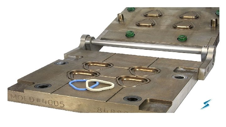
1. CLASSIFICATION OF COMPRESSION MOLDS Types of compression molds I. Hand compression mould II. Semi compression mould A. B. C. A. semi automatic open flash mould semi automatic vertical flash mould semi automatic fully positive mould & semi automatic landed positive mould semi automatic semi-positive moulds
1. Hand compression mould Hand compression molds are used for smaller production runs or prototypes, experimental jobs that require lower mould costs and parts having open tolerances and less intricacy. Advantages ü Generally high bulk material are used for processing large deep drawn parts of maximum density ü These moulds are used advantageously for complex parts incorporating number of loose pull pins and wedges ü Hand moulds weigh less than 15 kg for easy manual handling and the operations are fully manual. ü The hand moulds are less costly Disadvantages ü Hence the hand moulds are slow in operation which requires longer cycle time and is labor intensive, adding to production cost as compared to other type of moulds. ü Moulds are more easily damaged by misalignment, mishandling etc. , which may result from improper mould operation and closing of the mould ü Flash must removed in the land areas and additional pressure pads should be provided outside the cavity to have better mould life.
high bulk material
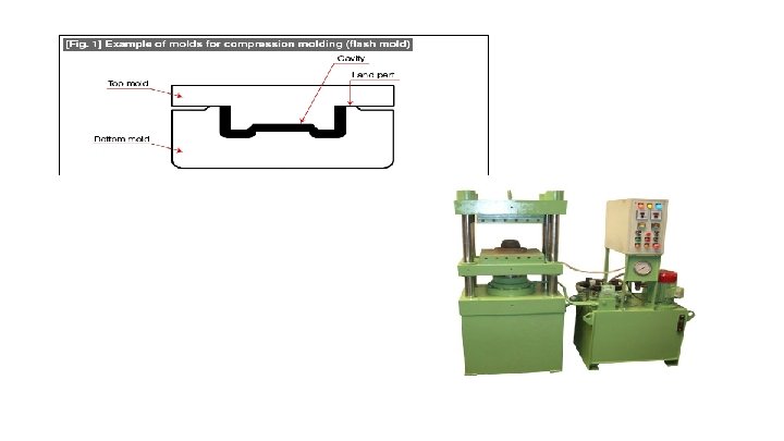
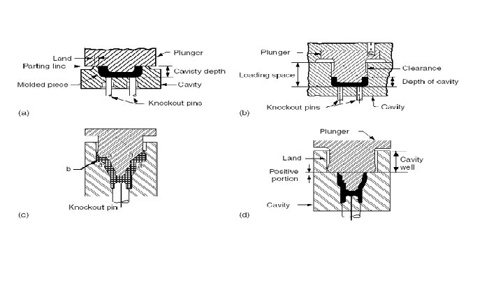
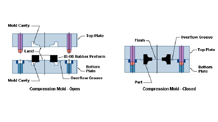
2. Semi automatic open flash mould The flash type compression mould is used to produce shallow shaped components Flash formation q In this mould a slight excess of molding powder is loaded into the mould cavity. q On closing the top and bottom platens, the exceed material is forced out and flash is formed. Advantage of flash formation The flash blocks the plastic remaining in the cavity causes the mould plunger to exert pressure on it. Gas or air can be trapped by closing the mould too quickly, and finely powdered material can be splashed out the mould ü Since the only pressure on the material remaining in the flash mould when it is closed results from the high viscosity of the melt which did not allow it to escape, Disadvantage of open flash mould ü Because of lower pressure exerted on the plastic in the flash moulds, the molded products are usually less dense than when made using other moulds. ü Moreover, because of the excess material loading needed, the process is somewhat wasteful as far as raw materials are concerned. ü ü Advantage of open flash mould ü However, the process has advantage that the moulds are cheap, and very slight labor costs are necessary in weighting out the powder. However, the moulds are suitable for building up into tools containing many impressions. ü Resins having high melt viscosities can be molded by this process.
2 -B Semiautomatic vertical flash type mould These types of moulds are suitable for molding components of high-density and critical dimensions as related to cavity and top force. ü Easy removal of flash on large parts and leaves no flash line scars on the side of the parts Clearance ü There is very little clearance between the plunger and the cavity wall. ü In the positive mould, almost all the pressure is exerted on the material and a very little material is allowed to escape as flash, the clearance between the plunger and cavity varies between 0. 035 mm to 0. 135 mm per side, depending on the size of the mould and the material to be molded. Flash ü The flash is formed vertically on the type of the mould. ü Flash is formed on every piece part molded by the compression method. ü The thickness and position of this flash depends on the design of the mould, type of material being molded, and accuracy of the mould. ü Flash is removed by filling, sanding and tumbling Disadvantage of the positive type ü The disadvantage of the positive type of mould is that after frequent operation the cavity walls become scored and ejection of piece parts is difficult. Advantage of the positive type ü The positive mould is used primarily with material containing coarse fillers and the amount of material placed into the mould cavity. ü It must be measured accurately as there is very limited means for the excess material escape. ü
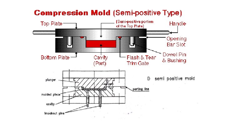
2 -CSemi automatic semi-positive moulds The semipositive mould is a combination of the features of open flash and fully positive moulds and allows for excess powder and flash. Flash • It is also possible to get both horizontal and vertical flash. Clearance ü A clearance of 0. 025 mm per side, for a diameter of 25 mm between the plunger (top force) and the cavity is maintained for satisfactory operation of mould. ü Moreover, the mould is given a 20 taper on each side of the cavity for allowing the flash to flow on and the entrapped gases to escape along with it, thereby producing a clean, blemish-free mould component Disadvantage of semi-positive mould ü Semipostive moulds are more expensive to manufacture and maintain than the other type compression moulds. Advantage of semi-positive mould ü Semipositive moulds are suitable for producing components to close tolerance and better surface finish.
FACTORS THAT INFLUENCE THERMOSET MOULDING Three important factors that must be considered in thermoset moulding are; 1. Temperature 2. Pressure and 3. Cure time
I. Temperature Heating temperature for moulding materials For thermoset: The majority of thermosetting compounds must be heated to approximately 1900 C for optimum cure. For various moulding materials: Temperature for moulding the various materials can be determined by experimentation or by getting the information from the manufacturer of the particular material. Temperature variation At high temperature: Higher temperatures may degrade some of the physical properties or electrical characteristics of the material and particularly in transfer moulding, may cause the material procure before the cavity is completely filled. High temperatures may also cause blisters and burn spots on the finished articles. At low temperature: Temperatures which are too low do not allow the material to flow properly and result in incompletely cured piece parts of poor consistency, thus reducing the productivity of the cycle. At optimum temperature: There is generally an optimum temperature which produces the best flow characteristics for the particular material and cavity.
I. Temperature FACTORS AFFECTING MOULD TEMPERATURE FACTORS: The exact mould temperature not only vary with the material used and the type of mould, But also with geometry of the moulded articles, and whether loose powder or pre-heated performs are used. Pre-heat temperature Need of pre heat temperature: Because plastics are generally good heat-insulating materials preheating of the charge is often used to shorten the time in the moulding. Preheat temperature range: Pre-heat temperature are commonly between 660 C and 1480 C , higher temperature are possible when heat is more rapidly transferred to the material. Frictional heat temperature Frictional heat: Another source of heat input to the plastic during the moulding process is from frictional heat during the closing of the mould. In compression molding: In the case of compression moulding, the material is forced in to flow by the closing of the mould. This flow may be at fairly high localized velocities, which impart a certain amount of frictional heat energy to the plastic.
I. Temperature Factors affecting mould temperature In transfer moulding, the frictional heat is even more pronounced as the material is forced along runners and through relatively small gates leading to the cavities. The amount of frictional heat added to the material in transfer moulding is dependent on the speed of the plunger advance, the size and configuration of runners and gates and the surface finish of the mould. It must be taken in to consideration when using relatively heat-sensitive materials. Mould temperatures must be maintained with ± 30 C for the best results.
• II. Pressure Need of pressure ü Molding with thermosetting plastics requires greater pressure for two basic reasons: ü To ensure that the plastic fills all of the cavity and has relatively uniform density throughout. (pressure causes the cavity to fill and resists the tendency of internal gases to form voids or gas pockets, pressure must be sufficient to overcome resistance of the plastic to flow) ü To ensure better heat transfer to the material (Higher pressure produces a higher density, which generally means faster thermal conductivity). Pressure in compression moulding For phenolic materials: ü In compression moulding a pressure of 211 kg/cm 2 has been found suitable for phenolic materials. But some material manufacturers recommending that 158 kg/cm 2 is sufficient. But normally this pressure is low and it is sufficient for easy flow materials and a simple uncomplicated shallow moulded shape. For moulding urea and melamine material: ü For moulding urea and melamine material, pressures of 2 times that needed for phenolic material are necessary (i. e) approximately 315 kg/cm 2, again adding 19. 3 kg/cm 2 per cm of depth in excess of 2. 54 cm is added for material without pre-heat.
• II. Pressure For a medium flow material: ü For a medium flow material and where there is a number of average sized recesses, cores, shapes and pins in the moulding cavity where the material has to flow in to small intricacies and to produce a good quality hard packed and dense moulding. A pressure of 211 kg/cm 2 or above is necessary. For deeper the moulding- simple rule ü Also the deeper the moulding cavity, the more pressure is required and a fairly simple rule is to add approximately 19. 3 kg/cm 2 per cm of depth in excess of 2. 54 cm if cavity depth (maximum up to 30 cm depth) for the material without pre-heat. For the material with pre-heat: ü For the material with pre-heat, the pressure approximately 70 kg/cm 2 or above, is required and for deeper moulding a pressure of 6. 9 kg/cm 2 per cm depth in excess of 2. 54 cm is added
II. Pressure In transfer moulding Comparison with C/M and T/M ü For transfer moulding, generally pressure of 3 times the magnitude of those required for compression moulding are require. For phenolic material ü It is possible some times to mould with a pressure of between 527 kg/cm 2 – 562 kg/cm 2 but in general, a pressure of 632 kg/cm 2 and above is required for phenolic material, the pressure referred to here being that applied to the powder material in the transfer chamber (material without pre-heat). Pressure- Affecting factors ü Depending upon the configuration of the moudling, the design of mould (eg. Whether direct sprue type or that employing a runner system) and the flow properties of the grade of material used.
III Cure Time Definition of cure time: ü The period required to harden thermosetting materials to partial or complete polymerization is called the cure-time. ü Many compounds produces parts that are hard enough, blister free and apparently cured, yet the polymerization of the resin system is not complete and a post back cycle may be required to optimize properties. The curing time variables are as follows: Material Temperature To achieve the minimum cure time, the material must be at the maximum temperature when it is loaded in the moulds. Material may be pre-heated by using infra-red lamps, radio frequency preheaters and extrudates formed from screw feed material in a heated barrel.
III Cure Time Mould Temperature ü The designer must have knowledge of the recommended mould temperature for each type of material and he arrives at the maximum mould temperature and cycle that will produce high quality parts at the shortest overall cycle. Material type ü General purpose materials having wood flour, cotton flock, cellulose, paper and so on offer the greatest molding latitudes, Mineral and glassfilled materials are more heat sensitive and are more difficult to mould. ü Adjustments of pre-heat temperature, plasticity and mould temperature must be studied to obtain the optimum mould cycle.
III Cure Time Cross-Sectional Area ü The cross-sectional area or wall thickness will determine the cure time required to produce the part. ü A cross section up to 2 -3 mm thick will cure in a matter of second, where as increased wall sections may require minutes. ü Parts having thicknesses or cross-sectional areas in excess of 9. 5 -13 mm may be difficult to mould by compression when to establish minimum cure cycles; transfer or injection methods of moulding might be better. Degree of cure ü Determining the degree of cure, regardless of the mould process used, is vitally important in establishing four important factors. ü ü Achievement of maximum moulded density Achievement of proper moulded part rigidity The optimum point for moulded part ejection The basis for dimensional stability of the moulded parts.
Filler Type Plasticity Pressure Requirements Shrinkage Variations MATERIAL SELECTION IN RELATION TO MOULDING CONDITIONS
MATERIAL SELECTION IN RELATION TO MOULDING CONDITIONS Filler Type Bulk factor: ü The compression method of moulding is limited to materials that have a bulk factor of 3: 1 or less. In addition, the material must have a good funnel flow rating. Fiber and fillers: ü Fillers that produce high bulk or rag fibers, long glass fibres, sisal and long mineral fibers. General purpose materials: ü General purpose materials containing wood flour, cotton, cellulose and so on cause no problems in moulding. Electrical or heat-resistant materials: ü Electrical or heat-resistant materials containing mineral or glass may be heat sensitive and are more difficult to mould.
• MATERIAL SELECTION IN RELATION TO MOULDING CONDITIONS Plasticity Material-plasticity ü The plasticity of a material is its softness or stiffness as it flows in the cavity. For softer materials: ü Softer materials require less pressure to mould. Selection of plasticity: ü The process engineer must select the proper plasticity to produce high-quality parts with a minimum of pressure.
MATERIAL SELECTION IN RELATION TO MOULDING CONDITIONS Pressure Requirements Minimum moulding pressure: ü Minimum moulding pressures are desirable to hold mould maintenance to a minimum. Excessive pressure: ü Excessive pressure could cause mould damage due to breaking small pins or delicate se-in mould sections or projections. ü There is also the possibility of damaging the land area, causing is to sink or crack. ü Excessive moulding pressures or extremely tight moulds may cause over densification to the extent that parts will expand when remove from the mould. ü Sufficient pressure, however, must be used to assure maximum density in the moulded parts.
MATERIAL SELECTION IN RELATION TO MOULDING CONDITIONS Shrinkage value: ü Parts must be of proper density to assure consistent shrinkage value. General purpose materials: ü General purpose materials having fillers result in higher shrinkage rates than are obtained when other fillers are used. Glass filled materials: ü If extremely close tolerances required, material having fillers such as glass and mineral should be selected. Variations ü The process engineer and the design engineer may have to work together to select the material that will meet the needs of both, so that the moulded part will satisfy the end product requirements.
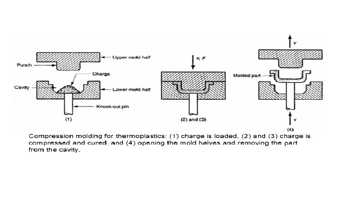
DESIGN OF THE MOULD CAVITY Video: compression molding
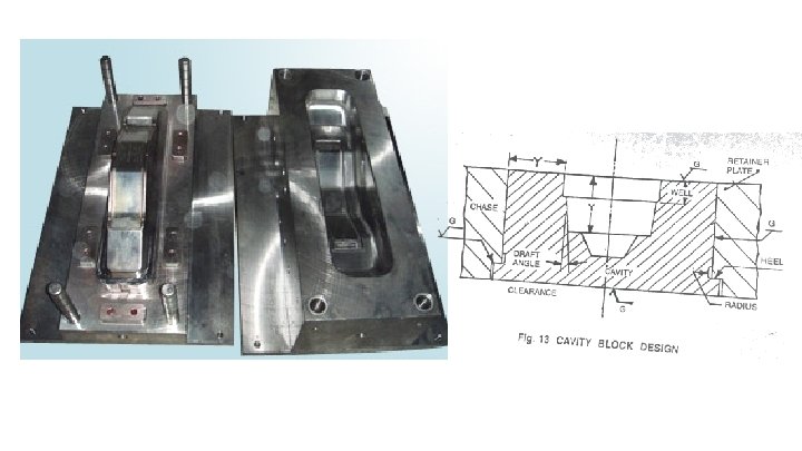
DESIGN OF THE MOULD CAVITY Strength of cavity: For adequate strength, the mould cavity should have dimensions sited to withstand the clamping pressure, to prevent distortion within the tolerance limits of deformation. Cavity block design The below figure shows a cavity block mounted in a retainer plate with some of the construction details.
DESIGN OF THE MOULD CAVITY Mould cavity arrangement Draft angle: ü A slight modification is made on the piece part in order to illustrated the draft angle and other feature clearly. Radius: The radius located at the heel block is machined or ground as an undercut. ü This radius serves a number of purposes. ü The radius acts as clearance for the grinding wheel as the external surface and heel are ground to size. ü The radius also serves to minimize stress concentration and to prevent cracking during heat treatment. ü Another function of the radius is to provide clearance between the machined pocket in the retainer plate and the cavity block. .
DESIGN OF THE MOULD CAVITY Mould cavity arrangement Retainer plate: ü Since the cavity and plunger of compression moulds are hardened, the surface must be ground to fit properly in the retainer plate. Ground surfaces are indicated in figure. Clearance: ü Clearance is also provided between the heel of the cavity block and the counterbore in the retainer plate. Mould cavity design for adequate strength ü For adequate strength, horizontal distance “Y” should approximately equal depth “Y” as in figure ü the cavity will not distort under the molding pressure, ü And provisions must be made to eject the molding from the cavity or plungers.
DESIGN OF THE MOULD CAVITY Calculation of Strength of cavity dimensioning Assumption: The mould cavity is assumed to be a pipe with a thickwall an internal compression, The total compression pressure is acting only within cavity Determination of wall thickness The wall thickness can be determined by the following equation. a) For tough materials, the outer pressure being = 0 r 0 = ri √хadm + pc xadm - pc cm ---------------- (1) b) For rigid (hardened materials) r 0 = ri √хadm + pc (1 -k) xadm - pc (1 -k) cm ---------------(2) where r 0 = radius of the outer part ri = radius of the inner part pc = compression pressure per unit area xadm =admissible stress k ≈ 0. 25 = ratio of the tensile and compressive strength of the material A comparison of equation (1) and (2) shows that equation (1) is a special case of equation (2) with K = 0
Calculation related to-Number of Cavities, Clamping force, shot weight
Calculation related to-Number of Cavities, Clamping force, shot weight Number of cavities based on clamping force for compression mold Clamping force is the force which is required to hold both mold half in closed position press against the compression pressure. Clamping force (kgf) = projected area of the moulding (cm 2) x compression pressure of the Plastic material (kgf/cm 2) Projected area Calculating projected area The projected area is the total area of the molding Projected area = (WXH)-(wxh) shown in View C WXH =Area of the cavity which sets up pressure opposing the clamp (view –A) w x h = the moulding has a central cut-out opening of dimension (View- B) Figure: projected area
Calculation related to-Number of Cavities, Clamping force, shot weight Projected area calculation various types of compression mold ü For vertical flash or positive type mould ü The compression pressure will be acted fully on the plastic materials ü Hence, projected area in the case of vertical flash or positive type mould = the projected area of the component For horizontal mould ü The compression pressure provides the horizontal flash. ü Hence, the horizontal flash should be added in the projected area in calculation of no. of cavities ü Projected area in horizontal flash mould = 1. 2 x projected area of the component Compression pressure Generally, it is recommended that minimum molding pressure of 240 kg/cm 2 of projected area be used However, in practice, about 300 kg/cm 2 of projected area is used to compensate for any variables that may be encounted Determine the no. of impression based on clamping force After finding the clamping force required for one impression, the number of impressions can be determined from the actual clamping force available for a particular machine No. of impression = clamping force available on the machine clamping force required for an impression
Advantages and disadvantages of compression molds Advantage of compression mold Tolerance: Best method for holding close tolerances over the projected area of flash line Shrinkage: Lower mold shrinkage as compared to transfer or injection. 0. 0015 -0. 002 in. /in. , less on general purpose phenolic materials. Uniform mold shrinkage due to uniform flow pattern of material. Density: more uniform density of molded parts Weld lines: Depending on the geometry of the part, no weld lines and fewer molded –in strains and stresses because of more uniform fill of cavity. Venting: Venting of mold may be needed, but not to the extent required in transfer or injection molding.
Advantages and disadvantages of compression molds Advantage of compression mold Flash: Generally, flash scrap lower than transfer or injection, unless runnerless injection considered. Runner system: On shallow draw parts, maximum number of cavities per bed area due to less molding pressure, and without the necessity of ling runner systems and sprue or plunger locations. Suitable products: Recommended for shallow draw parts. Large parts having large projected areas, deep draw, and weights above 3 lb (13. 3 N) can readily be molded Product strength Cost: Improved impact strength, since no degradation of fibers during flow. Generally compression molds are less costly to construct than transfer or injection molds. Landed direct positive may be an exception. Depending on the geometry of the part, and the suitability for automatic molding using optimum molding conditions, the piece part cost and tooling costs may be more economical than molding by transfer or injection
Disadvantage Processing conditions may alter and affect these advantages; The following disadvantages may be associated with compression molding. Cure time: Rates of cure of heavy sections or wall thickness may be longer than those for transfer or injection molding. On sections of 0. 400 in. (10 mm) thickness, special compression equipment may be able to equal cure. Mold maintenance: Part designs incorporating undercuts or side draws are troublesome because high mold maintenance is required. Part design requiring thin steel sections may result in high mold maintenance costs because the material is not plasticized as the mold is closed Molded-in holes are limited to depths of 2. 5 times diameter. Small through holes not recommended. Flash: Dimensions over flash line limited to +0. 008 – 0. 000 in. (+0. 2 – 0. 000 mm) Process difficult Difficult to mold high bulk materials. Hardening Parting lines may be damaged by collapsing of side walls. Hard surfaces and deep case hardening required on mold force and cavity.
8 9 10 11 12 13 14 Transfer molding- types, principles Design of pots and plunger, Feed system Economic determination of the no. of cavity and Technological Determination of the no of cavity Design of mould cavity and Design of load chamber Transfer tonnage, shot weight. Heat losses and energy requirement to heat the mould Advantage and disadvantage of T/M Tutorial venting comparison C/M and T/M Bulk factor 4. 15 1. Discuss the principles involved in transfer moulding. Briefly explain different types of transfer moulding (16) (2005) 2. discuss the design of pot and plunger for transfer mould (2005) explain the feed system for transfer mold 2. 121 1. Derive the equation for economic 3. 14 4. 13 determination of the number of cavities in the moulds. Explain each term involved in it (16 3. 10 write in detail about the design of loading 4. 8 chamber how to determine the transfer tonnage 3. 17 4. 10 1. Derive equations for the electrical energy requirements to heat the transfer mould. 4. 23 1. what are the advantages and disadvantages of transfer moulding? Explain (8) (2005 1. Discuss about vent dimensions in the case of transfer moulds. 2. Write down the importance of vacuum venting in transfer moulding process. (2005) 1. Write the advantages of transfer mould over compression mould Why bulk factor is limited to 2 in case of transfer mould?
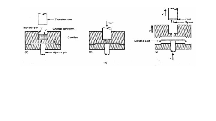
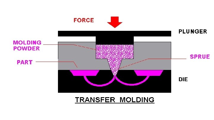
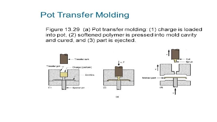
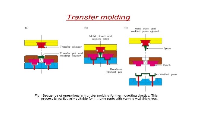
Types of transfer mould Transfer moulds are of semiautomatic type and are made in single and multiple cavities. Types of transfer mould 1. Pot type transfer mould 2. Plunger type transfer mould 2 -A. Top plunger transfer mould 2 - B. Bottom plunger transfer mould
Design of Pot and Plunger
Design of Pot and Plunger
1. 2. 3. 4. 5. 6. 7. 8. 9. 10. 11. 12. 13. 14. Made of pot and plunger Shape of pot and plunger Area of the pot Volume of the pot: Bulk factor: For sufficient strength Radius Clearance: Adjusting the plunger at heat state Cull pick up Sealing groove Venting: Sprue: Solution for adjusting plunger at heat state Made of pot and plunger Both the pot and plunger are made from a good grade of wear resistant tool steel which is heat treated and ground. . Shape of pot and plunger Pots and plungers are made square, rectangular or round in shape. The shape is determined by the shape of the piece part, number of cavities and available space in the mould base. Round pots and plungers are preferred because less machining difficulties are encountered. Area of the pot The area of the pot should be 20% to 30% greater than the projected area of all the cavities and runners. The dimensions of the pot, if it is round or square, can be calculated once the area is known.
1. 2. 3. 4. 5. 6. 7. 8. 9. 10. 11. 12. 13. 14. Made of pot and plunger Shape of pot and plunger Area of the pot Volume of the pot: Bulk factor: For sufficient strength Radius Clearance: Adjusting the plunger at heat state Cull pick up Sealing groove Venting: Sprue: Solution for adjusting plunger at heat state Volume of the pot: To determine the volume of the pot, the total volume of all the piece parts, the runner and the sprue, plus a small amount for a 0. 375 to 0. 75 mm thick cull, is approximately calculated. At least twice this volume is to be used for the pot volume. Knowing the area and the volume, one can easily arrive at the depth of the pot by dividing the volume by the area. The additional volume in the pot is provided to compensate for the bulk factor of the performs used and to allow the plunger to enter the pot a short distance before exerting pressure on the material. Bulk factor: High bulk factor materials are generally not used in transfer moulding. The bulk factor of the performs used in transfer moulding is approximately 1 to 2. () .
For sufficient strength, horizontal distance “Y” should be equal to the depth of the pot “Y” Radius 1. 5 to 3 mm radius is provided at the top edge of the pot. 1. 5 mm radius is machined at the bottom of the pot to facilitate the flow of the material and to simplify the machining of the corner. 2. 5 to 3 mm radius is machined at the bottom of the plunger. The difference in the radii on the plunger and the bottom of the pot results in a clearance so that the plunger will not wedge in the pot but will land on the flat surface of the pot. Clearance: • In assembly there is a small clearance between the plunger and the transfer pot. • A clearance of 0. 025 to 0. 075 mm per side is provided between the pot and plunger. • This clearance keeps the bearing surface narrow to prevent galling, and allows flash and excess material to escape. .
Adjusting the plunger at heat state Adjusting the plunger to the chamber when expanded by heat prevented its entrance in the cold state was difficult. So it frequently occurred that the plunger was forced into the pot strongly on clamping the mould and there was seizing and cracking and other damage occurred. Solution for adjusting plunger at heat state This problem is solved by adjusting the plunger to the cold pot with running fit, but permitting material flow around the plunger so as to form a collar when solidified according to the hot pot size, thus preventing material flow out, during moulding. Sealing groove A sealing groove approximately 2. 5 mm wide and 0. 8 mm deep is cut in to the perimeter or periphery of the plunger. During the operation of the mould this groove fills with the moulding material and act as a natural seal, allowing very little material to escape past the bearing surface of the plunger. .
Venting: Flats or grooves are ground on the bearing surface of the plunger for venting purposes. Sprue: The sprue and the interior of the pot is polished so the material can flow easily. The sprue has a taper of 20 to 30 per side. The large diameter of the sprue varies in size from 9 to 12 mm with a 1. 5 to 3 mm radius at the entrance of the sprue. The small diameter (at the runner or piece part) varies from 3 mm to 6 mm depending on the size of the piece part. Cull pick up Wedge –shaped slots called cull pick up are machined in to the plunger. The thick or heavy section of the cull pickup is located directly above the sprue as shown in the fig. The length of the cull pick up varies from 3 to 6 times the diameter of the sprue, depending on the location of the sprue and the diameter of the pot. The width is generally 2 to 3 times the diameter of the spure. .
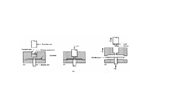
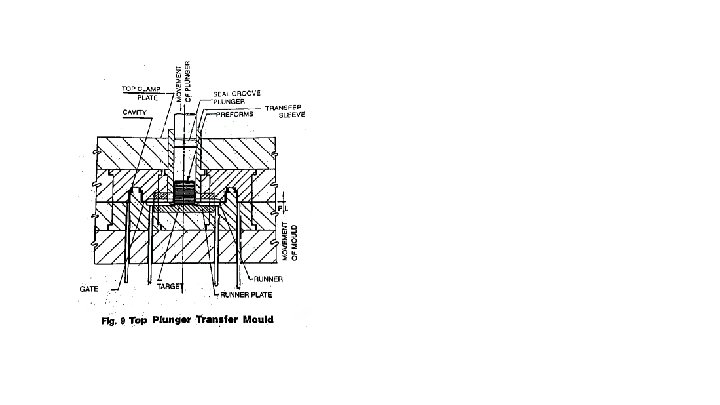
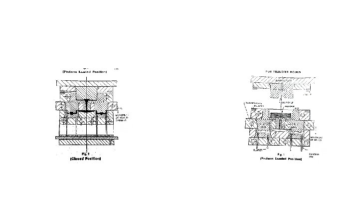
Plunger Transfer Moulds Diagram: Fig illustrates the plunger type of transfer mould in the closed position with the performs in the target area and the plunger on its downward stroke.
Difference between the pot and plunger: The plunger transfer differs from the pot transfer. In that the plunger is the part of the molding press and not a part of the mould itself. Sprue By the use of this plunger, the sprue is eliminated and a very thin cull of small area is formed above the target area, thus reducing the loss of material. Filling of cavities The preheated performs are placed or stacked in the target area The mould is closed, the performs are lifted into the transfer sleeve. Once the mould is completely closed, the plunger is activated for its downward stroke The combination of the heat of the mould and the pressure of the plunger on the perform causes the material to become fluid and to flow through the runners and gates into the cavities.
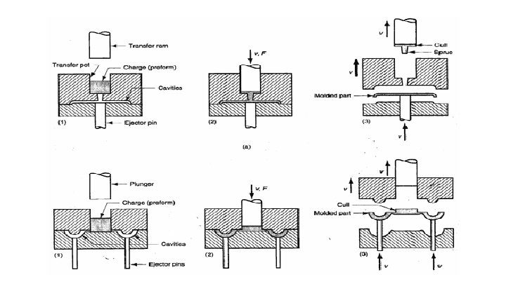
Types The plunger transfer classified as a. Top Plunger transfer b. Bottom Plunger transfer a. Top plunger mould is a two plate mould in which the performs, tablets are placed into the space provided in the mould. The plunger is the part of press and not to the part of mould. The press plunger moves downward and applied the pressure on the charge. Due to heat and pressure in the cylinder, thermoset material changes its state from solid to liquid. This liquid is forced into the cavity by runner and gate and sprue is not required as pot type transfer mould. The material gets cured in the cavity and the press is opened and the part is get ejected by knockout pins b. bottom plunger transfer molding Bottom plunger mould is a two plate mould. The performs, tablets are placed into the sleeve, cylinder or space provided in the mold and plunger is the part of press and not to the part of the mould The bottom plunger moves upward and applies the pressure on the charge Due to the heat and pressure in the cylinder, the charge changes its state from solid to liquid.
Feed system for Transfer mold
Feed system for Transfer mold The success of transfer molding depends on ideal design of the sprue, runner and the gate Design of sprue for transfer mold In single cavity mould: The sprue leads directly to the mould cavity in a single cavity mould. In multi-cavity moulds: In multi-cavity moulds material flows through the runners from the sprue to the mould cavities
Design of Runner for transfer mould Trapezoidal design The trapezoidal design requires higher Practically there is no rule for runner dimensioning. But it is desired that the shortest possible runner should plunger pressures and causes lower cavity fill be designed. than the full round or half round runners. Runner diameter Half round runner Greater runner diameter The half round runner is easy to polish and A greater diameter is desirable for promoting because of the semicircular contour, the material flow and a low transfer pressure, nut, molded runner releases easily form the Smaller runner diameter mould. As material is deposited in the runners after each injection, reduce the runner diameter to the This probably the most popular type of minimum. Hence, greater runner diameter is runner found in mould design though it advantageous. requires higher injection pressure and slower The pressure needed forcing the material fill times than the full round runner. through and the period of material flow are considerably increased by decreasing the Full round runner diameter, thus limiting diameter It has been proved that full round runner will reduction. result in faster cavity fill, with lower plunger Types of Runner used in transfer mould pressure, than with either half round or There are three basic types of runners used in transfer moulds trapezoidal runners. Trapezoidal runner Full round runners are particularly recommended half round runner for transfer moulding. and full round runner Rule for runner dimension
Design of Gate for transfer mold There is a “gate” at the end of the runner immediately before the cavity. The kinetic energy of the material is here transformed into heat and it is at this point that heating of the material is most rapid. Gates of multi-cavity moulds serve a double purpose: first the uniform heating of the material, Secondly, to insure a de-gate of the molded part without any trace. For this a gate with small diameter is desirable. Gate design Various gate designs may be used with transfer moulds. They are Rectangular gate, Half round And full round gate. Gate design factors However, actual runner and gate design and recommended areas depend upon the following factors; Geometry of the molded part Location of the gate or gates Molding pressure desired Number of cavities Plasticity and heat sensitivity of the material selected for the application and Physical properties required in the moulded part
Determine the sprue, gate and runner • The minimum sprue area or, with multi-cavity moulds, the sum of gate areas may be determined from the formula A = GK Where A (mm 2) = the minimum runner area and the sum of gate areas, G (gm/stroke) = weight of pieces produced at once K = value to be found in above table Recommended sprue and gate dimensions • From long experience, the runner and gate design of Fig are recommended by Du Bois and Pribble. These dimensions are listed in Table. TABLE : Sprue and Gate Dimensions Type of plastic powder Min. diameter Dmin R E C min K Wood flour phenolic 4 ½ (D+5 ) 2. 5 0. 8 0. 28 -0. 30 Cotton flock phenolic 5 -6 ½ (D+5 ) 3 1. 2 0. 32 -0. 36 Fabric-filled phenolic 6 -7 ½ (D+7 ) 4 1. 6 0. 37 -0. 42
Design of mould cavity and Design of load chamber
Design of mould cavity and Design of load chamber Need of loading chamber (powder well above the cavity) Plastic powder fed in to the mould has a greater need for more space (powder well i. e. loading chamber above the cavity) in a loose state than has the pressed molding. Hence, the mould cavity design must allow for sufficient space for the loose powder. For materials having high bulk factor Materials having high bulk factor often requires an extra high loading chamber (powder well) A removal loading chamber extension is fixed on the mould cavity Bulk factor = volume of the loose plastic powder / volume of the molding The ratio of the volume of the loose plastic powder to the volume of the molding is called bulk factor The inclusion of different fillers affects the bulk factor of the material. .
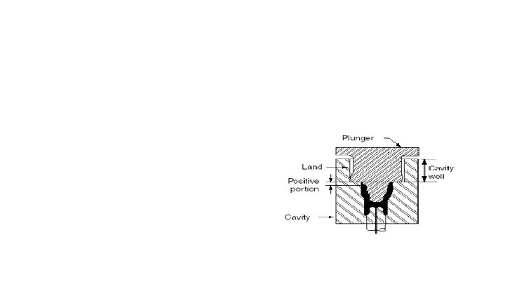
Size of the loading chamber The size of the charge (in unmolded powder form) decide the size of the powder well or space (loading chamber ) provided above the cavity impression Flare: The loading chamber has to be designed with a flare of 1/3 -1. Generally the start of the flare should lie only 4 -6 mm above the compacted molding. Edge The upper edge(s) should be rounded off with a radius R=2. 5 mm Land dimensions ü A land dimensions (i. e distance between the actual cavity dimension and the vertical wall of the powder well) of between 4 to 9 mm on normal sized moldings is desirable ü To take the more charge of molding materials ü The mould powder well (above the mould cavity) should be made deeper (9 mm) ü The area (radius of well) of powder well is not practiced to increased
Calculation of loading chamber depth D = VA – VC / A Where D – Depth of loading space from top of cavity to pinch-off land V – volume of actual cavity space (CM) V- total volume of loose powder (cm) A-Projected area of the loading chamber (cm) V- Total volume of part including flash factor 10 -20%. In this way the depth of loading chamber can be determined Advantages of powder well ü Two advantages are obtained by keeping the powder well area as small as is practicable ü Molding pressure is increased ü Less obstruction is put in the way of the escaping excess molding material (flash)
Transfer tonnage, shot weight Transfer Pot calculations The clamping pressure provided by the chamber is an important consideration. Of the total cavity area is greater than the total pot area, the hydraulic pressure exerted by the plastic compound would tend to open the mould at the parting line. To ensure perfect mould locking, the area (A P) should be 25% -30% greater than the combined area of the molding surface and the area of all runners and sprue. The dimensions of the pot, if it is round or square can be calculated once the area is known. Total area of pot A P = Total projected area of cavities, runners and sprue + 25% -30% of total projected area Volume of pot V P = Total volume of all the piece parts, the runners and the sprue plus approximate volume of a small amount for a 0. 5 to 1 mm thick cull multiplied by Bulk factor of the compound. Depth of pot = VP AP
Calculation aspects 1. Ram load C) To maintain balance where transfer moulds employ an integral pot a) Transfer ram load required (tonf or tf) 2 2 = area of transfer plunger (in or cm ) × pressure required to Area of pot (in 2 or cm 2) = projected area of mould cavities transfer oulding material (tonf/ in 2 or tf/cm 2) and runners (in 2 or cm 2) The pressure required for transfer moulding the particular material With adequate gates and runners the to be employed my be obtained from the material projected area of the mould may sometimes exceed that of manufaturer’s data, e. g. for phenolic 3 -6 tonf/in 2 (472 -945 the pot, although conservative practice adopts the reverse kgf/cm 2) the area of the pot exceeding that of the mould by amounts varying from 10 to 25 % b) Main ram load required to clamp mould (tonf or tf) = pressure developed by transfer ram (tonf/ in 2 or tf/cm 2) × Projected area of moulding at flash face, including runners (in 2 or cm 2) + (bottom transfer) area of transfer pot (in 2 or cm 2) A safety margin of clamp over transfer pressure of 10 -20% is added. Press tonnage required for integral pot moulds is given by Main ram load (tonf or tf) = area of transfer pot plunger (in 2 or cm 2) × pressure available to Transfer molding material tonf/in 2 or tf/cm 2
Heat losses and energy requirement to heat the mould
Heat required to raise the mould to operating temperature is given by Q = Q 1 + Q 2+ Q 3+Q 4+Q 5 Where Q = The heat required for heating of the mould Q 1 = heat loss by conduction Q 2=heat loss by radiation Q 3=heat loss by convection Q 4=heat required to raise the temperature of the material to operating temperature Q 5=heat required for heating plastic material Q 1 = Heat loss by conduction During compression or transfer molding process heat from the mould will be transferred by conduction from the mould plates to the mould platens thereby causing loss of heat due to conduction. This heat loss can be calculated by using formula Q 1= (k A T)/t Where k=Thermal conductive of asbestos or other used insulation A=Total area of the mould plates through which heat is transferred towards the platen T =the temperature difference between the mold plates and other plates from platen side or platen t=Total thickness of the asbestos material
Q 2 =Heat loss by radiation Initially compression or transfer molds are heating in closed position so the only radiation losses are fro the vertical faces of the mould plates. However, the mould opens horizontal faces are also exposed for a certain period of time so this should also be taken into consideration. This heat loss can be calculated by using the formula Q 2 =1. 38 X 10 -9 ( T 2 +460)4 X A 2 Where Q 2=Heat loss by radiation 1. 38 X 10 -9 =Steffan Boltzmann constant for rough finished tool surface A 2=Surface area of exposed tool faces T 2=Temperature of mould in C Q 3 =Heat loss by convection • Heat in compression will be transferred by convection from the vertical faces of the mould. • During the mould is in closed condition and convention heat transferred from vertical faces only Q 3 = (0. 7 + T 3 / 375) T 3 A 2 where Q 3=Heat lost by convection A 2=Area of vertical faces of the mould T 3 =The temperature difference between mould plates and room temperature
Q 4=heat required to raise the temperature of the material to operating temperature The initial heat required to raise the tool Q 5=heat required for heating plastic from room temperature to operating temperature considering the heat losses material • Heat required to cure the moulding material can be calculated is given by Q 5 = m 2 x CP 2 X T 5 Q 4 = m 1 x CP 1 X T 4 Where m 2 =Weight of mould CP 2=Specific heat capacity of moulding Where material m 1=Weight of mould T 5=Temperature rise required from room CP 1=Specific heat capacity of the mould steel temperature to moulding temperature T 4 =Temperature rise from room temperature to operating temperature
Advantage and disadvantage of T/M Advantage Tolerance: Tolerances over the flash line may be held to ± 0. 002 in. (0. 05 mm) provided the mold is constructed properly and does not flash. Cure time: Reduced cure as compared to compression molding, especially in thick sections. Flash: Smaller diameter holes with longer lengths can be molded; through holes may be molded flash free ( does not flash. ) Minimum flash line; parts easily finished with regard to flash removal (provided an automatic degate cycle or pinpoint or tunnel gate is use). Strength: Depressions with thin steel sections are not subject to breakage. Higher physical tensile and flexural strength values, especially in the direction of flow Molding Parts having side cure slides are more easily molded. Maintenance; Less mold maintenance. Mold inserts Molded-in inserts are more easily done.
Advantage and disadvantage of T/M Disadvantage Gate Joining Vent Scrap Gate or sprue removal necessary unless pinpoint or tunnel gate is used. Gate location may cause warpage due to uneven fill or lack of density. Depending on gate location, circular parts may be considerably out-of –round. Diaphragm gates may result in radial cracks around the gate area. Gate must be selected and located to avoid or minimize weld lines. Ball jointing may be a problem. Mold vents and activated vent pins may be required. Material scrap loss is higher, since sprue or cull, runners, gates, and vents are scraped for each mold cycle. In compression molding no such scrap is produced. Shrinkage More chance of molded-in stress that causes uneven shrinkage, warpage, and weakness in the part. Number of cavities may be limited to runner length and mold design around a single center transfer cylinder. Also high molding pressures required for multiple cavities. Part weight and size limited. Large flat parts are subject to flow lines Process Difficult to automate cycle. An operator is normally needed. Cost Mold costs may be more than compression molds. Maintenance Mold erosion of cavities, runners, and gates may become high mold maintenance factor.
Trapezoidal design The trapezoidal design requires higher plunger pressures and causes lower cavity fill than the full round or half round runners. Half round runner The half round runner is easy to polish and because of the semicircular contour, the molded runner releases easily form the mould. This probably the most popular type of runner found in mould design though it requires higher injection pressure and slower fill times than the full round runner. Full round runner It has been proved that full round runner will result in faster cavity fill, with lower plunger pressure, than with either half round or trapezoidal runners. Number of cavities may be limited to runner length and mold design around a single center transfer cylinder. Also high molding pressures required for multiple cavities. Part weight and size limited. Large flat parts are subject to flow lines Process Difficult to automate cycle. An operator is normally needed. Cost Mold costs may be more than compression molds. Maintenance Mold erosion of cavities, runners, and gates may become high mold maintenance factor.