Next Generation Space Interconnect Standard NGSIS Space VPX






- Slides: 89
Next Generation Space Interconnect Standard (NGSIS) Space. VPX and Space. VPXLite Tutorial VITA 78 AND VITA 78. 1 WORKING GROUPS
Bottom Line Up Front What is wrong with just using Legacy Space Systems? • Legacy space systems are often point solutions • Re-use is not a priority • Don’t have the full range of redundancy options (dual-string, M-of-N, etc. ) built-in given the particular application and its needs. • Internal interfaces are often proprietary and application specific • Modules are not designed to inter-operate at either hardware or software level
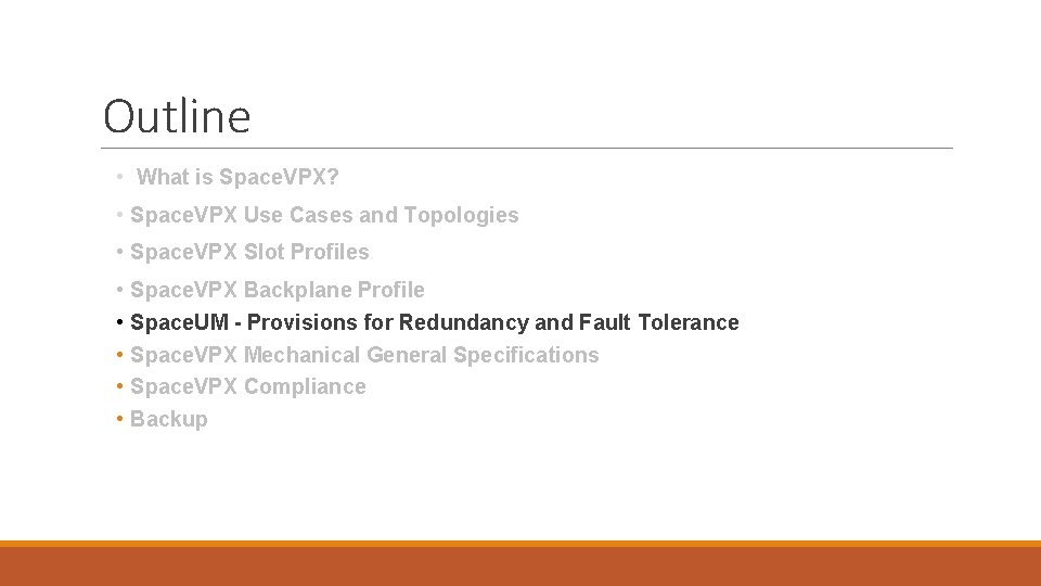
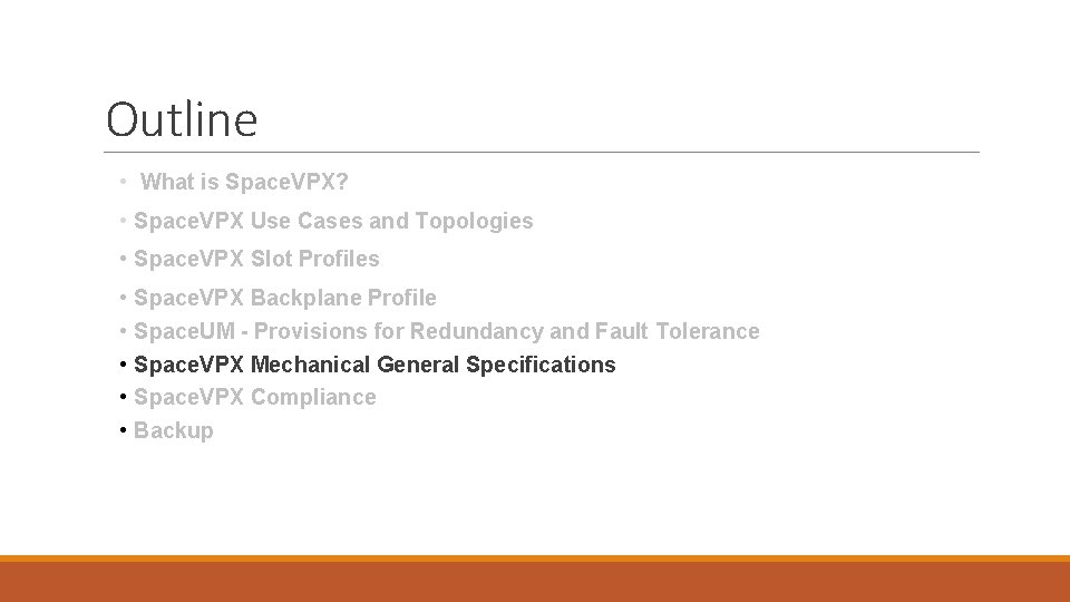
Outline • What is Space. VPX? • Space. VPX Use Cases and Topologies • Space. VPX Slot Profiles • Space. VPX Backplane Profile • Space. UM - Provisions for Redundancy and Fault Tolerance • Space. VPX Mechanical General Specifications • Space. VPX Compliance • Backup
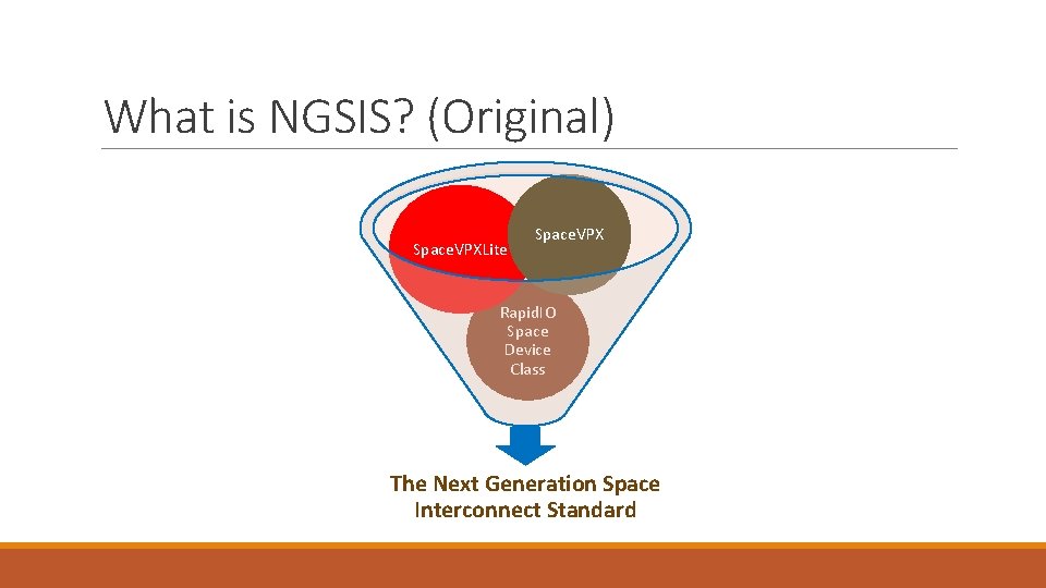
What is NGSIS? (Original) Space. VPXLite Space. VPX Rapid. IO Space Device Class The Next Generation Space Interconnect Standard
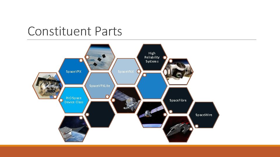
Constituent Parts High Reliability Systems Space. VNX Space. VPXLIte RIO Space Device Class Space. Fibre Space. Wire
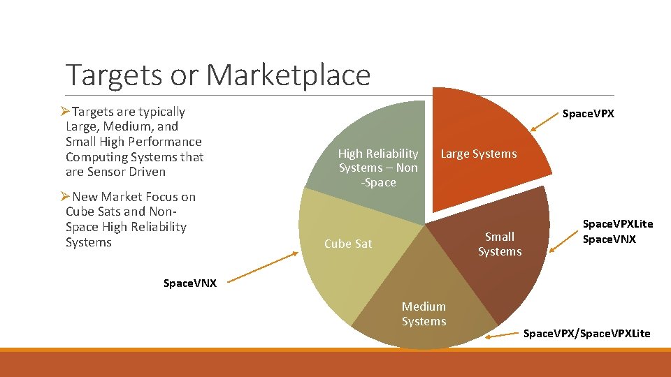
Targets or Marketplace ØTargets are typically Large, Medium, and Small High Performance Computing Systems that are Sensor Driven ØNew Market Focus on Cube Sats and Non. Space High Reliability Systems Space. VPX High Reliability Systems – Non -Space Large Systems Small Systems Cube Sat Space. VPXLite Space. VNX Medium Systems Space. VPX/Space. VPXLite
Who is Involved in Space. VPX?
Who is Involved in the RIO Space Device Class?
What are Space. VPX’s Goals? Created to bridge the VPX standards to the space market. • Space. VPX addresses both interoperability (as Open. VPX does) and space application needs (not in Open. VPX). • Space. VPX defines Payload, Switch, Controller, and Backplane module profiles to meet needs of space applications • Space. VPX adds features to the Utility Plane for fault tolerance • Point-to-point not bussed to tolerate faults: failure on module does not affect entire system. • Space Utility Module added to provide dual-redundant source for Utility Plane implementations. • Space. VPX defines use of Space. Wire for Control Plane over Ethernet (Open. VPX preferred solution).
Goals for Space. VPX and Space. VPXLite? Develop • Enhanced set of backplane specifications that are based upon existing commercial standards with added features required for space applications. Increase • Interoperability and compatibility between manufacturers and integrators, while simultaneously increasing affordability through the use of standard sets of hardware. Scale • Performance and Capability based upon user’s needs and requirements
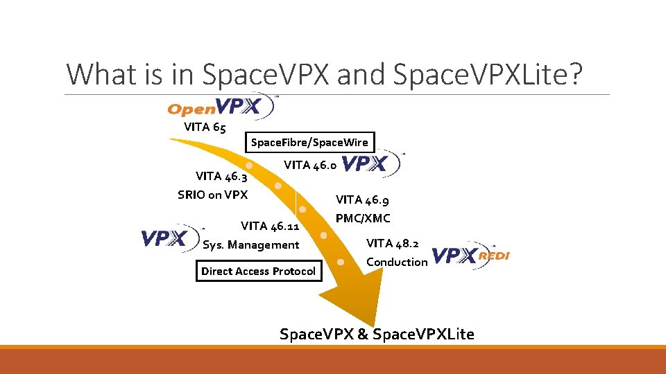
What is in Space. VPX and Space. VPXLite? VITA 65 Space. Fibre/Space. Wire VITA 46. 3 VITA 46. 0 SRIO on VPX VITA 46. 9 VITA 46. 11 Sys. Management Direct Access Protocol PMC/XMC VITA 48. 2 Conduction Space. VPX & Space. VPXLite
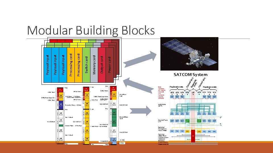
Payload input Payload input Payload input Processing card Processing card Switch card Memory card Output card Power card Modular Building Blocks SATCOM System
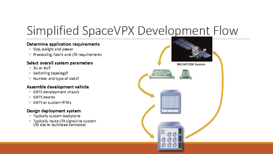
Simplified Space. VPX Development Flow Determine application requirements • Size, weight and power • Processing, fabric and I/O requirements Select overall system parameters • 3 U or 6 U? • Switching topology? • Number and type of slots? Assemble development vehicle • COTS development chassis • COTS boards • COTS or custom RTMs Design deployment system • Typically custom backplane • Typically route I/O signals to custom I/O slot or bulkhead connector
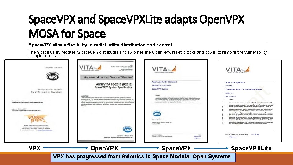
Space. VPX and Space. VPXLite adapts Open. VPX MOSA for Space. VPX allows flexibility in radial utility distribution and control The Space Utility Module (Space. UM) distributes and switches the Open. VPX reset, clocks and power to remove the vulnerability to single point failures. VPX Open. VPX Space. VPXLite VPX has progressed from Avionics to Space Modular Open Systems
Updates as Part of the VITA 78 Revision ØLarge number of editorial fixes missed in original and not qualified as errata ØReorganized protocol sections to include utility plane protocols and register structure ØAdded Space. Fibre as an alternate control and data plane on all modules ØEnhanced Direct Access Protocol (DAP) for lightweight operation ØAllows Control Plane to access DAP registers in addition to Utility Plane ØAdded redundant Geographical Address for fault tolerance ØRestricted slot locations for certain module types ØReorganized Space. UM sections making it follow document’s profile structure
Updates as Part of the VITA 78 Revision ØAdded smaller overhead 3 U Space. UM Modules that serve 5 logic slots ØAdded a small number of new slot / module profiles ØAdded new power supply, power switch and utility signal switch slots / modules ØLowered power on 3 U modules to match Space. VPXLite’s 187. 5 m. W/mm ØAdded additional module pitches for daughter cards and 3 D constructs ØAdded missing 3 U mechanical drawings ØAdjusted mechanical keep-out areas Ø 3 U wedge-locks set to 250 and VITA 48. 2 interoperable module handling described ØAdded Coax and Fiber connector options on slot and module profiles Most changes in current draft - completion / ratification targeted for 2 H 18
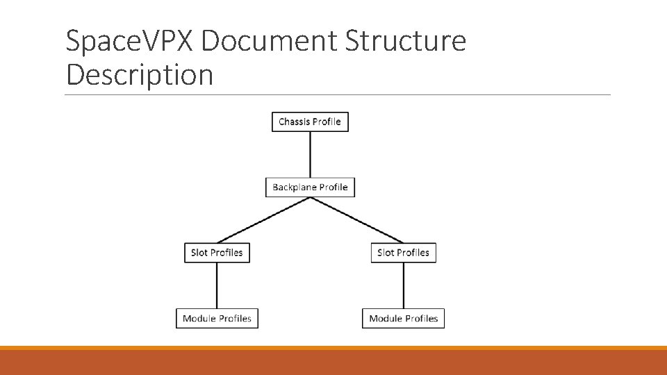
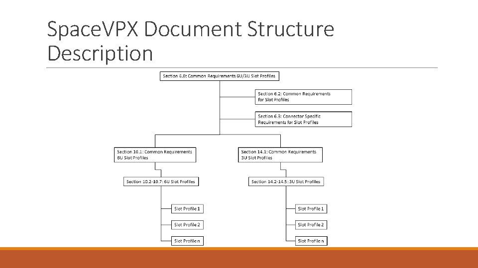
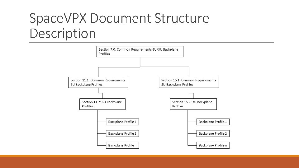
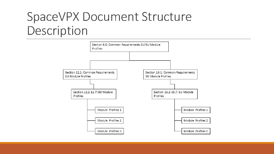
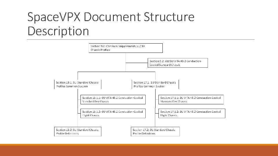
Space. VPX Document Structure Description
Space. VPX Document Structure Description
Space. VPX Document Structure Description
Space. VPX Document Structure Description
Space. VPX Document Structure Description
Outline • What is Space. VPX? • Space. VPX Base Use Case and Topologies • Space. VPX Slot Profiles • Space. VPX Backplane Profile • Space. UM - Provisions for Redundancy and Fault Tolerance • Space. VPX Mechanical General Specifications • Space. VPX Compliance • Backup
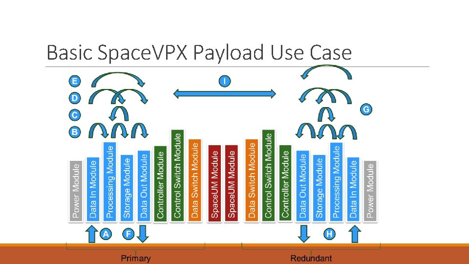
Basic Space. VPX Payload Use Case
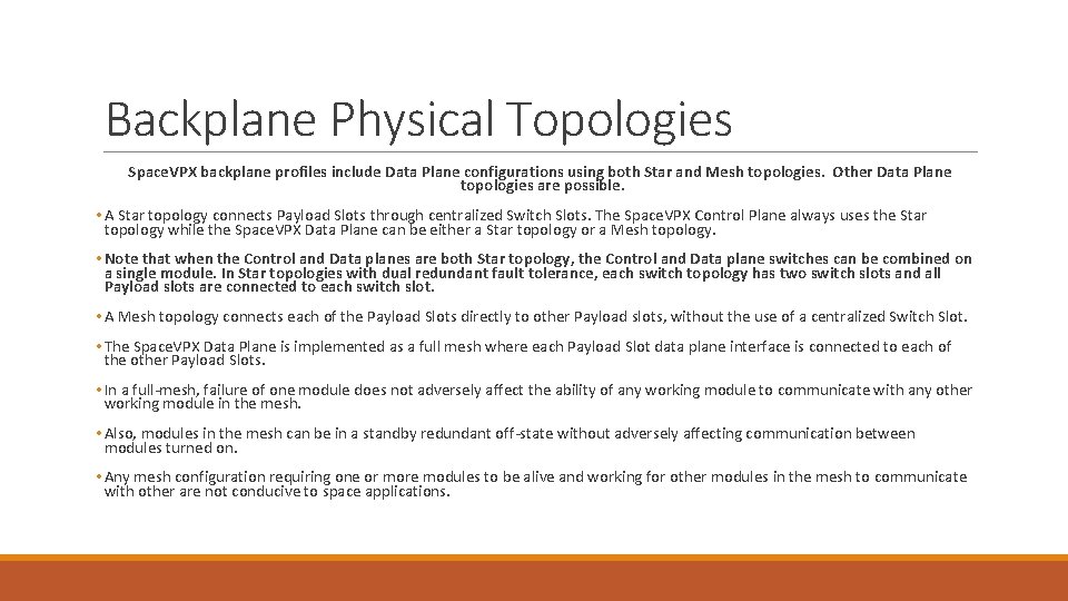
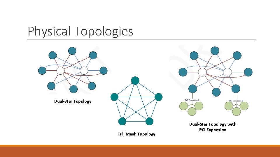
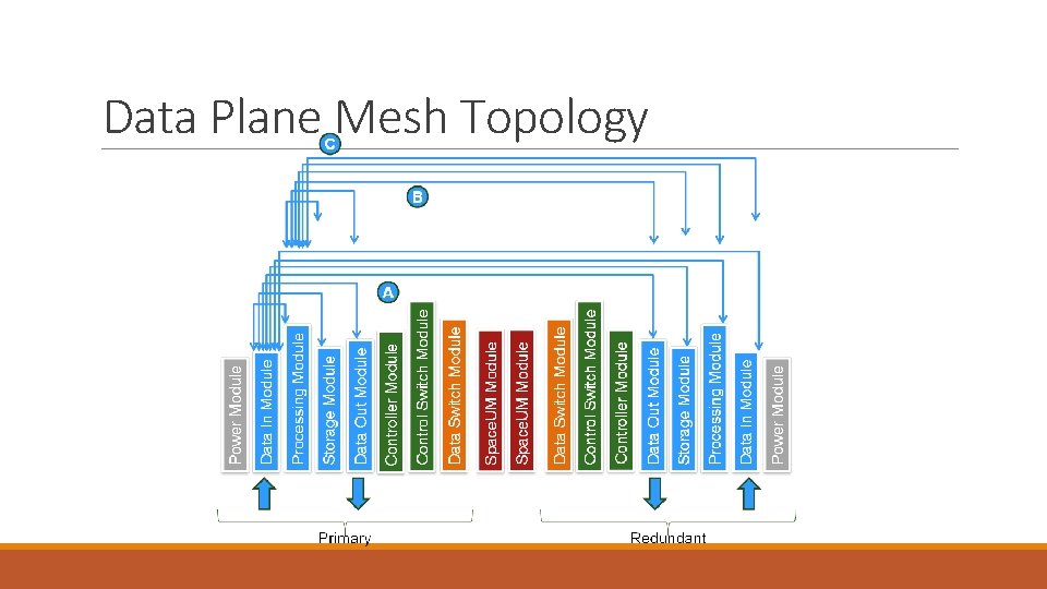
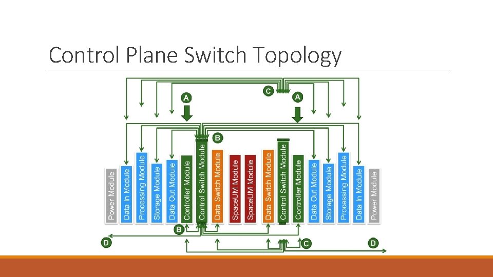
Backplane Physical Topologies Space. VPX backplane profiles include Data Plane configurations using both Star and Mesh topologies. Other Data Plane topologies are possible. • A Star topology connects Payload Slots through centralized Switch Slots. The Space. VPX Control Plane always uses the Star topology while the Space. VPX Data Plane can be either a Star topology or a Mesh topology. • Note that when the Control and Data planes are both Star topology, the Control and Data plane switches can be combined on a single module. In Star topologies with dual redundant fault tolerance, each switch topology has two switch slots and all Payload slots are connected to each switch slot. • A Mesh topology connects each of the Payload Slots directly to other Payload slots, without the use of a centralized Switch Slot. • The Space. VPX Data Plane is implemented as a full mesh where each Payload Slot data plane interface is connected to each of the other Payload Slots. • In a full-mesh, failure of one module does not adversely affect the ability of any working module to communicate with any other working module in the mesh. • Also, modules in the mesh can be in a standby redundant off-state without adversely affecting communication between modules turned on. • Any mesh configuration requiring one or more modules to be alive and working for other modules in the mesh to communicate with other are not conducive to space applications.
Physical Topologies Dual-Star Topology Full Mesh Topology Dual-Star Topology with PCI Expansion
Outline • What is Space. VPX? • Space. VPX Use Cases and Topologies • Space. VPX Slot Profiles • Space. VPX Backplane Profile • Space. UM - Provisions for Redundancy and Fault Tolerance • Space. VPX Mechanical General Specifications • Space. VPX Compliance • Backup
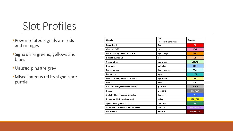
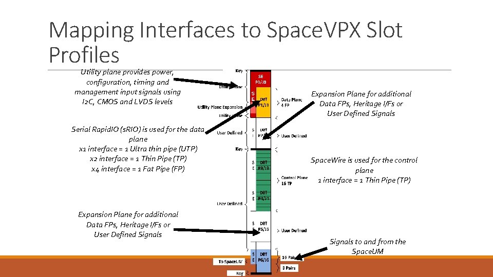
Slot Profiles • Power related signals are reds and oranges Signals Color (Microsoft Definition) Example Power Feeds Red PF VS 1, VS 2, VS 3 rose VS 1 VBAT, auxilary power, sense lines light orange UD (abbreviated UD) tan Control plane light green • Unused pins are grey Data plane pale blue DP 01 Expansion plane light turquoise EP 02 • Miscellaneous utility signals are purple PCI signals aqua control/data/Expansion plane, contrast light yellow DP 02 Grounds none GND Reserved Pins (abbreviated RSVD) grey 25% RSVD No pad grey 50% No Pad* Global Address, System Controller light blue GA Reference Clock, Auxiliary Clock yellow System Management, JTAG sea green SYSRESET, NVMRO, Maskable Reset lavender SYSRESET* Power select dark red Power SEL • Signals are greens, yellows and blues VBAT UD CPtp 02 PCI REF_CLK SM
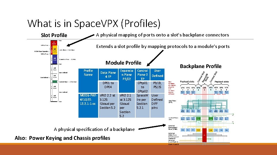
What is in Space. VPX (Profiles) Slot Profile A physical mapping of ports onto a slot’s backplane connectors Extends a slot profile by mapping protocols to a module’s ports Module Profile Name Data Plane 4 FP DP 01 to DP 04 MOD 6 -PAY- s. RIO 2. 2 at 4 F 1 Q 2 T 3. 125 12. 2. 1 -1 -cc Gbaud per Section 5. 2 Expansio n Plane P 2/J 2 s. RIO 2. 1 at 3. 125 Gbaud per Section 5. 2 A physical specification of a backplane Also: Power Keying and Chassis profiles Control Plane 2 TP CPtp 01 to CPtp 02 Space. W ire per Section 5. 2. 1 User Defined P 3/J 3, P 5/J 5 User Defined DIFF pins Backplane Profile
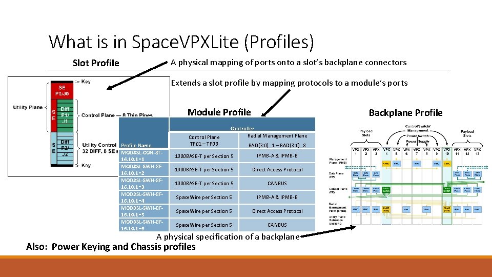
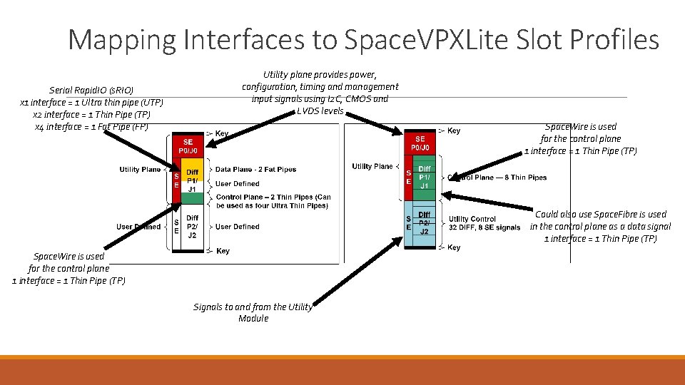
What is in Space. VPXLite (Profiles) Slot Profile A physical mapping of ports onto a slot’s backplane connectors Extends a slot profile by mapping protocols to a module’s ports Module Profile Name MOD 3 SL-CON-8 T 16. 10. 1‑ 1 MOD 3 SL-SWH-8 F 16. 10. 1‑ 2 MOD 3 SL-SWH-8 F 16. 10. 1‑ 3 MOD 3 SL-SWH-8 F 16. 10. 1‑ 4 MOD 3 SL-SWH-8 F 16. 10. 1‑ 5 MOD 3 SL-SWH-8 F 16. 10. 1‑ 6 Control Plane TP 01 – TP 08 Backplane Profile Controller Radial Management Plane RAD(3: 0)_1 – RAD(3: 0)_8 1000 BASE-T per Section 5 IPMB-A & IPMB-B 1000 BASE-T per Section 5 Direct Access Protocol 1000 BASE-T per Section 5 CANBUS Space. Wire per Section 5 IPMB-A & IPMB-B Space. Wire per Section 5 Direct Access Protocol Space. Wire per Section 5 CANBUS A physical specification of a backplane Also: Power Keying and Chassis profiles
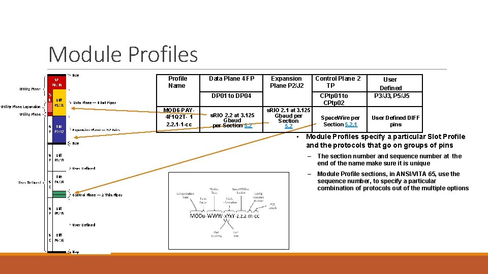
Module Profiles Profile Name Data Plane 4 FP Expansion Plane P 2/J 2 Control Plane 2 TP DP 01 to DP 04 MOD 6 -PAY 4 F 1 Q 2 T- 1 2. 2. 1 -1 -cc s. RIO 2. 2 at 3. 125 Gbaud per Section 5. 2 CPtp 01 to CPtp 02 s. RIO 2. 1 at 3. 125 Gbaud per Section 5. 2 Space. Wire per Section 5. 2. 1 User Defined P 3/J 3, P 5/J 5 User Defined DIFF pins • Module Profiles specify a particular Slot Profile and the protocols that go on groups of pins – The section number and sequence number at the end of the name make sure it is unique – Module Profile sections, in ANSI/VITA 65, use the sequence number, to specify a particular combination of protocols out of the multiple options
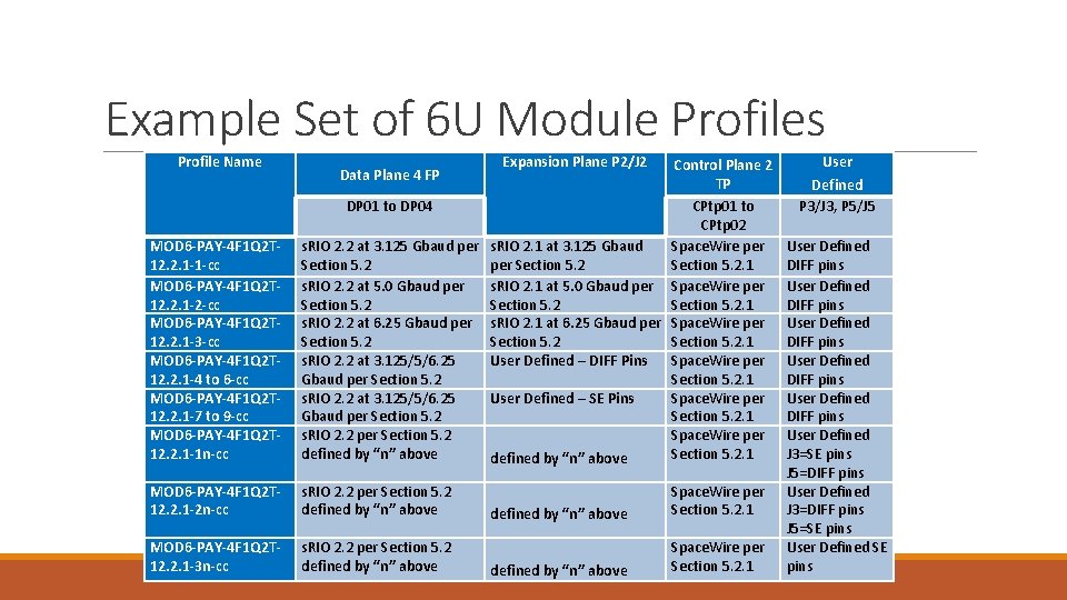
Example Set of 6 U Module Profiles Profile Name Expansion Plane P 2/J 2 MOD 6 -PAY-4 F 1 Q 2 T 12. 2. 1 -1 -cc MOD 6 -PAY-4 F 1 Q 2 T 12. 2. 1 -2 -cc MOD 6 -PAY-4 F 1 Q 2 T 12. 2. 1 -3 -cc MOD 6 -PAY-4 F 1 Q 2 T 12. 2. 1 -4 to 6 -cc MOD 6 -PAY-4 F 1 Q 2 T 12. 2. 1 -7 to 9 -cc MOD 6 -PAY-4 F 1 Q 2 T 12. 2. 1 -1 n-cc Control Plane 2 TP DP 01 to DP 04 CPtp 01 to CPtp 02 s. RIO 2. 2 at 3. 125 Gbaud per s. RIO 2. 1 at 3. 125 Gbaud Space. Wire per Section 5. 2. 1 s. RIO 2. 2 at 5. 0 Gbaud per s. RIO 2. 1 at 5. 0 Gbaud per Space. Wire per Section 5. 2. 1 s. RIO 2. 2 at 6. 25 Gbaud per s. RIO 2. 1 at 6. 25 Gbaud per Space. Wire per Section 5. 2. 1 s. RIO 2. 2 at 3. 125/5/6. 25 User Defined – DIFF Pins Space. Wire per Gbaud per Section 5. 2. 1 s. RIO 2. 2 at 3. 125/5/6. 25 User Defined – SE Pins Space. Wire per Gbaud per Section 5. 2. 1 s. RIO 2. 2 per Section 5. 2 Space. Wire per defined by “n” above Section 5. 2. 1 defined by “n” above MOD 6 -PAY-4 F 1 Q 2 T 12. 2. 1 -2 n-cc s. RIO 2. 2 per Section 5. 2 defined by “n” above MOD 6 -PAY-4 F 1 Q 2 T 12. 2. 1 -3 n-cc s. RIO 2. 2 per Section 5. 2 defined by “n” above Data Plane 4 FP defined by “n” above Space. Wire per Section 5. 2. 1 User Defined P 3/J 3, P 5/J 5 User Defined DIFF pins User Defined DIFF pins User Defined J 3=SE pins J 5=DIFF pins User Defined J 3=DIFF pins J 5=SE pins User Defined SE pins
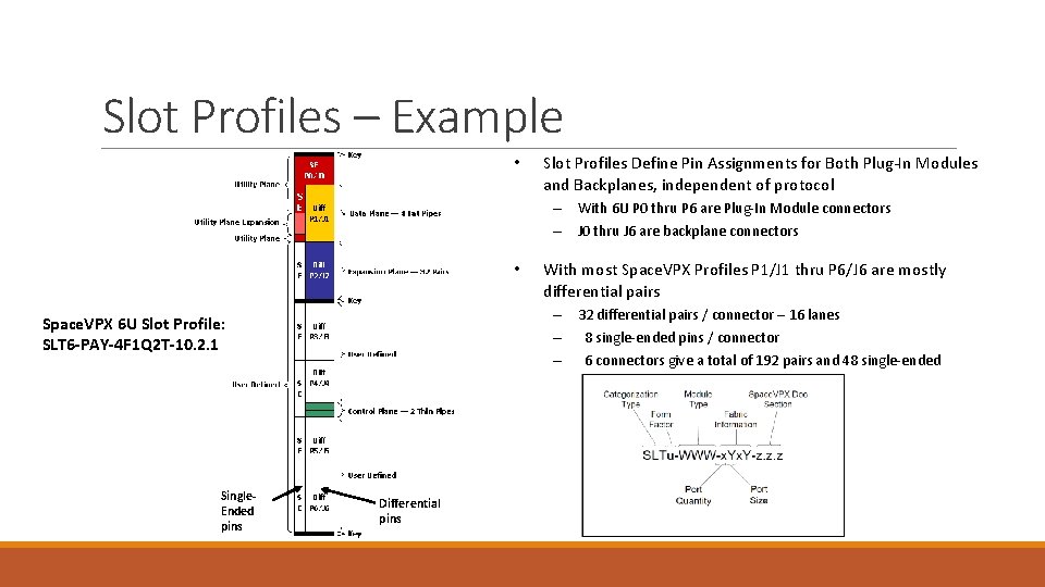
Slot Profiles – Example • Slot Profiles Define Pin Assignments for Both Plug-In Modules and Backplanes, independent of protocol – With 6 U P 0 thru P 6 are Plug-In Module connectors – J 0 thru J 6 are backplane connectors • – 32 differential pairs / connector – 16 lanes – 8 single-ended pins / connector – 6 connectors give a total of 192 pairs and 48 single-ended Space. VPX 6 U Slot Profile: SLT 6 -PAY-4 F 1 Q 2 T-10. 2. 1 Single. Ended pins With most Space. VPX Profiles P 1/J 1 thru P 6/J 6 are mostly differential pairs Differential pins
Mapping Interfaces to Space. VPX Slot Profiles Utility plane provides power, configuration, timing and management input signals using I 2 C, CMOS and LVDS levels Serial Rapid. IO (s. RIO) is used for the data plane x 1 interface = 1 Ultra thin pipe (UTP) x 2 interface = 1 Thin Pipe (TP) x 4 interface = 1 Fat Pipe (FP) Expansion Plane for additional Data FPs, Heritage I/Fs or User Defined Signals Space. Wire is used for the control plane 1 interface = 1 Thin Pipe (TP) Signals to and from the Space. UM
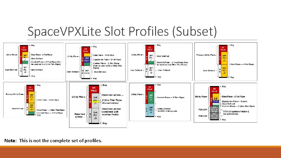
Mapping Interfaces to Space. VPXLite Slot Profiles Serial Rapid. IO (s. RIO) x 1 interface = 1 Ultra thin pipe (UTP) x 2 interface = 1 Thin Pipe (TP) x 4 interface = 1 Fat Pipe (FP) Utility plane provides power, configuration, timing and management input signals using I 2 C, CMOS and LVDS levels Space. Wire is used for the control plane 1 interface = 1 Thin Pipe (TP) Could also use Space. Fibre is used in the control plane as a data signal 1 interface = 1 Thin Pipe (TP) Space. Wire is used for the control plane 1 interface = 1 Thin Pipe (TP) Signals to and from the Utility Module
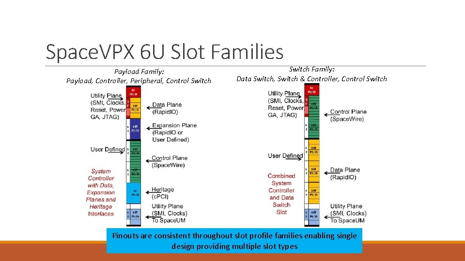
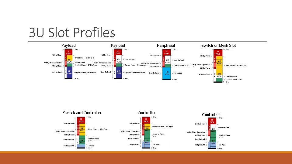
Space. VPX 6 U Slot Families Payload Family: Payload, Controller, Peripheral, Control Switch Family: Data Switch, Switch & Controller, Control Switch Pinouts are consistent throughout slot profile families enabling single design providing multiple slot types
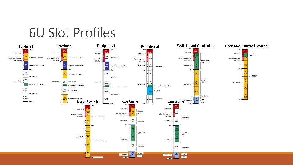
6 U Slot Profiles Payload Peripheral Data Switch Peripheral Controller Switch and Controller Data and Control Switch
3 U Slot Profiles Payload Switch and Controller Payload Peripheral Controller Switch or Mesh Slot Controller
Space. VPXLite Slot Profiles (Subset) Note: This is not the complete set of profiles.
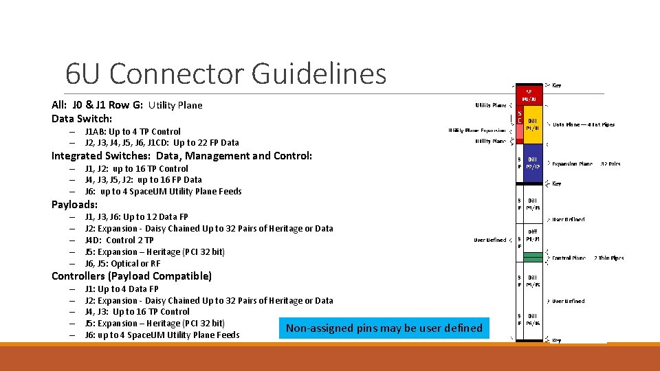
6 U Connector Guidelines All: J 0 & J 1 Row G: Utility Plane Data Switch: – J 1 AB: Up to 4 TP Control – J 2, J 3, J 4, J 5, J 6, J 1 CD: Up to 22 FP Data Integrated Switches: Data, Management and Control: – J 1, J 2: up to 16 TP Control – J 4, J 3, J 5, J 2: up to 16 FP Data – J 6: up to 4 Space. UM Utility Plane Feeds Payloads: – – – J 1, J 3, J 6: Up to 12 Data FP J 2: Expansion - Daisy Chained Up to 32 Pairs of Heritage or Data J 4 D: Control 2 TP J 5: Expansion – Heritage (PCI 32 bit) J 6, J 5: Optical or RF Controllers (Payload Compatible) – – – J 1: Up to 4 Data FP J 2: Expansion - Daisy Chained Up to 32 Pairs of Heritage or Data J 4, J 3: Up to 16 TP Control J 5: Expansion – Heritage (PCI 32 bit) Non-assigned pins may be user defined J 6: up to 4 Space. UM Utility Plane Feeds
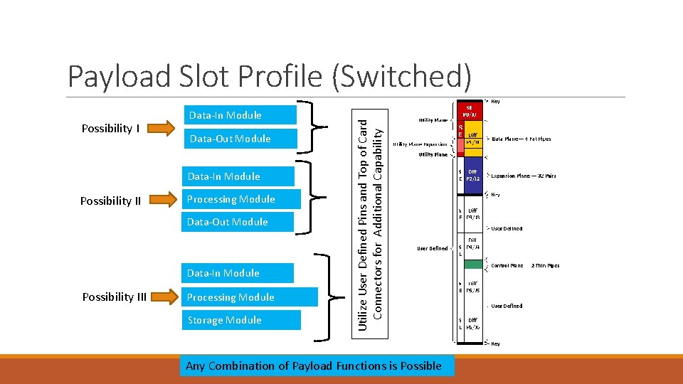
Possibility I Data-In Module Data-Out Module Data-In Module Possibility II Processing Module Data-Out Module Data-In Module Possibility III Processing Module Storage Module Utilize User Defined Pins and Top of Card Connectors for Additional Capability Payload Slot Profile (Switched) Any Combination of Payload Functions is Possible
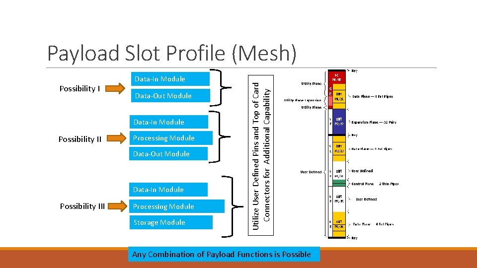
Possibility I Data-In Module Data-Out Module Data-In Module Possibility II Processing Module Data-Out Module Data-In Module Possibility III Processing Module Storage Module Utilize User Defined Pins and Top of Card Connectors for Additional Capability Payload Slot Profile (Mesh) Any Combination of Payload Functions is Possible
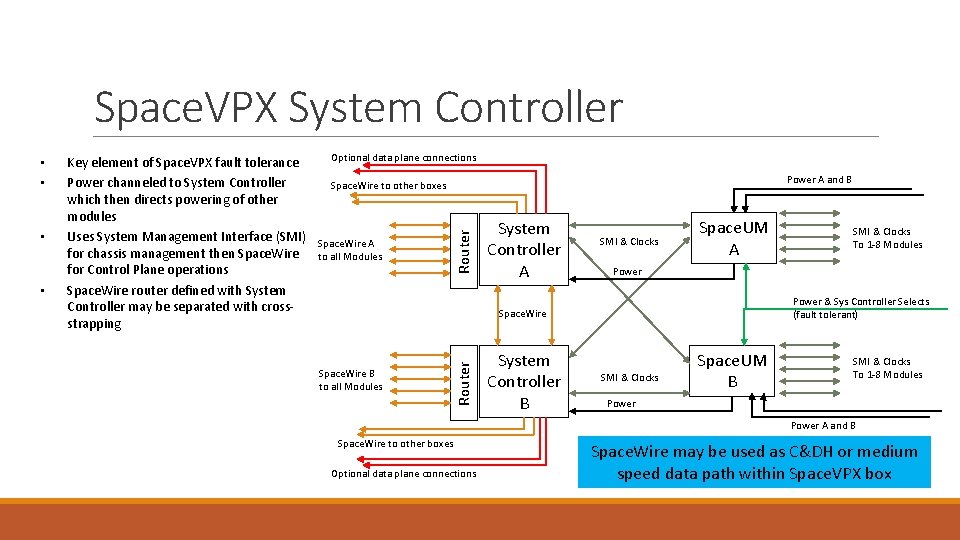
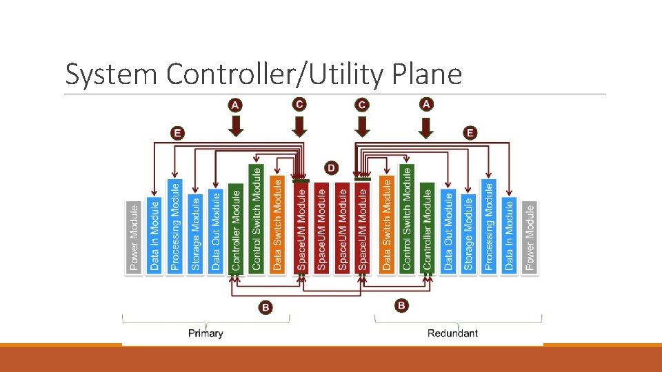
Space. VPX System Controller • Optional data plane connections Power A and B Space. Wire to other boxes Space. Wire A to all Modules Router • Key element of Space. VPX fault tolerance Power channeled to System Controller which then directs powering of other modules Uses System Management Interface (SMI) for chassis management then Space. Wire for Control Plane operations Space. Wire router defined with System Controller may be separated with crossstrapping System Controller A SMI & Clocks Space. UM A Space. Wire B to all Modules System Controller B SMI & Clocks To 1 -8 Modules Power & Sys Controller Selects (fault tolerant) Space. Wire Router • • SMI & Clocks Space. UM B SMI & Clocks To 1 -8 Modules Power A and B Space. Wire to other boxes Optional data plane connections Space. Wire may be used as C&DH or medium speed data path within Space. VPX box
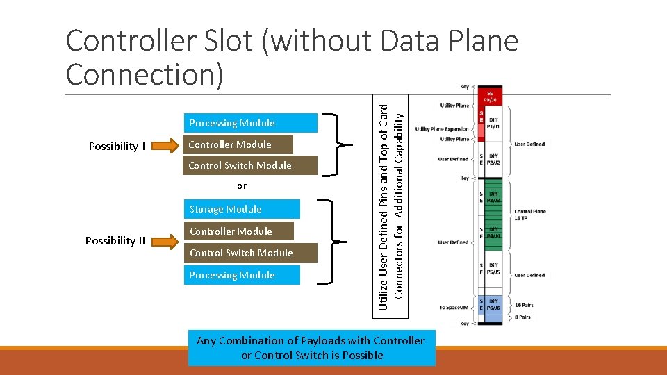
Processing Module Possibility I Controller Module Control Switch Module or Storage Module Possibility II Controller Module Control Switch Module Processing Module Utilize User Defined Pins and Top of Card Connectors for Additional Capability Controller Slot (without Data Plane Connection) Any Combination of Payloads with Controller or Control Switch is Possible
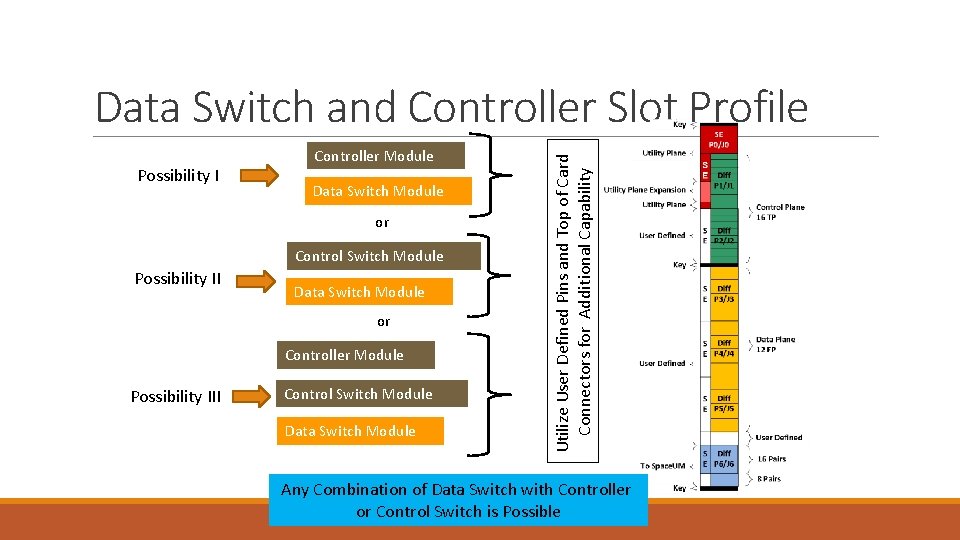
Possibility I Controller Module Data Switch Module or Control Switch Module Possibility II Data Switch Module or Controller Module Possibility III Control Switch Module Data Switch Module Utilize User Defined Pins and Top of Card Connectors for Additional Capability Data Switch and Controller Slot Profile Any Combination of Data Switch with Controller or Control Switch is Possible
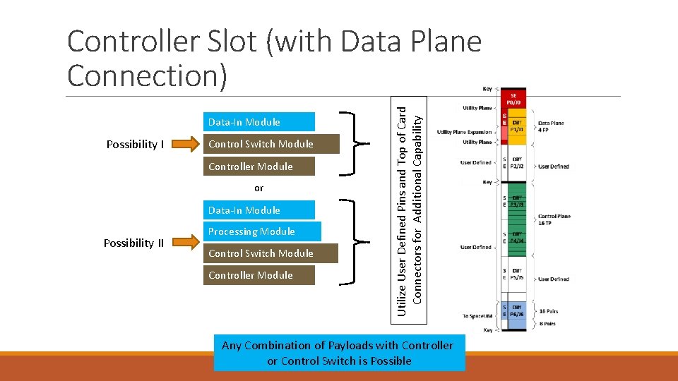
Data-In Module Possibility I Control Switch Module Controller Module or Data-In Module Possibility II Processing Module Control Switch Module Controller Module Utilize User Defined Pins and Top of Card Connectors for Additional Capability Controller Slot (with Data Plane Connection) Any Combination of Payloads with Controller or Control Switch is Possible
Outline • What is Space. VPX? • Space. VPX Use Cases and Topologies • Space. VPX Slot Profiles • Space. VPX Backplane Profile • Space. UM - Provisions for Redundancy and Fault Tolerance • Space. VPX Mechanical General Specifications • Space. VPX Compliance • Backup
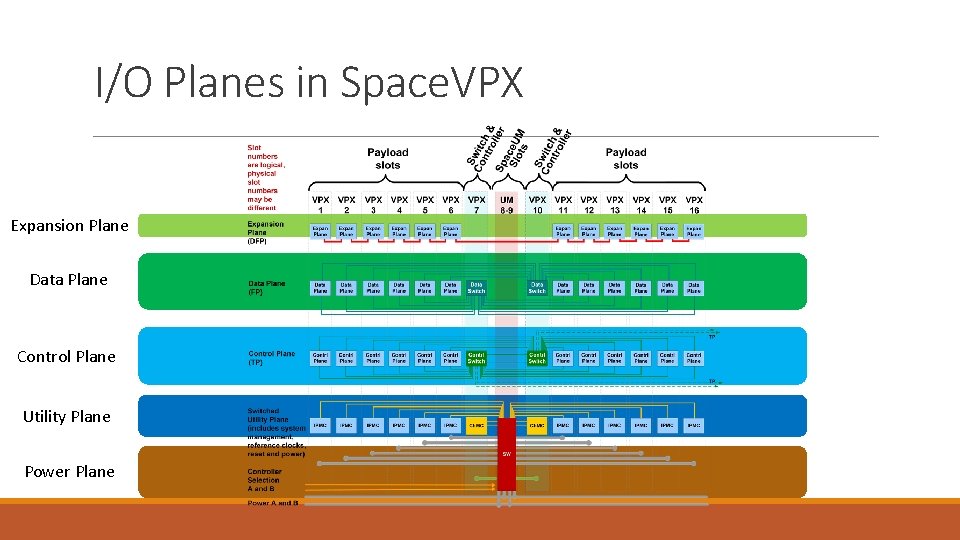
I/O Planes in Space. VPX Expansion Plane Data Plane Control Plane Utility Plane Power Plane
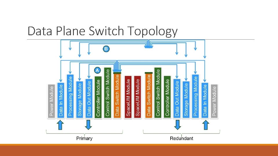
Data Plane Switch Topology
Data Plane Mesh Topology
Control Plane Switch Topology
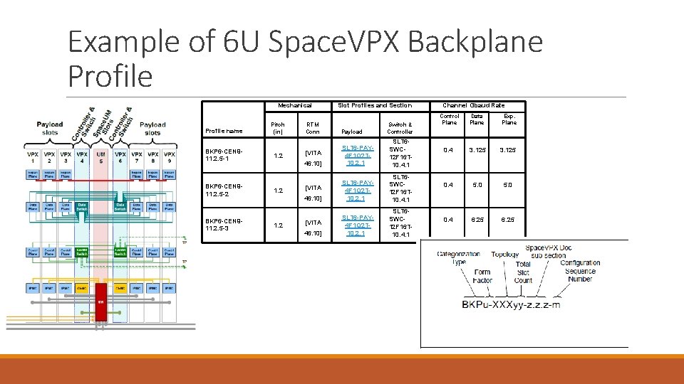
Example of 6 U Space. VPX Backplane Profile Mechanical Profile name BKP 6 -CEN 911. 2. 5 -1 BKP 6 -CEN 911. 2. 5 -2 BKP 6 -CEN 911. 2. 5 -3 Payload 46. 10] [VITA 1. 2 46. 10] 1. 2 SLT 6 SWC 12 F 16 T 10. 4. 1 SLT 6 -PAY 4 F 1 Q 2 T 10. 2. 1 SLT 6 SWC 12 F 16 T 10. 4. 1 [VITA 46. 10] Switch & Controller SLT 6 -PAY 4 F 1 Q 2 T 10. 2. 1 [VITA 1. 2 RTM Conn Pitch (in) Slot Profiles and Section Channel Gbaud Rate Control Plane Data Plane Exp. Plane 0. 4 3. 125 0. 4 5. 0 0. 4 6. 25
Outline • What is Space. VPX? • Space. VPX Use Cases and Topologies • Space. VPX Slot Profiles • Space. VPX Backplane Profile • Space. UM - Provisions for Redundancy and Fault Tolerance • Space. VPX Mechanical General Specifications • Space. VPX Compliance • Backup
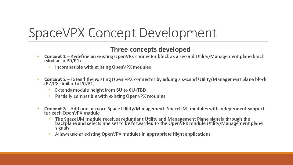
Space. VPX Concept Development Three concepts developed • Concept 1 – Redefine an existing Open. VPX connector block as a second Utility/Management plane block (similar to P 0/P 1) • Incompatible with existing Open. VPX modules • Concept 2 – Extend the existing Open VPX connector by adding a second Utility/Management plane block (P 7/P 8 similar to P 0/P 1) • Extends module height from 6 U to 6 U+TBD • Partially compatible with existing Open. VPX modules • Concept 3 – Add one or more Space Utility/Management (Space. UM) modules with independent support for each Open. VPX module • The Space. UM module receives redundant Utility and Management Plane signals through the backplane and selects one set to be forwarded to the Open. VPX module Utility/Management plane signals • Allows use of existing Open. VPX modules in appropriate flight applications
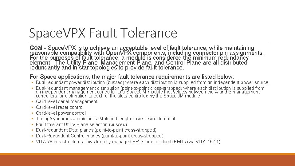
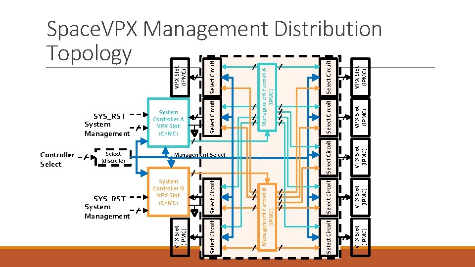
Space. VPX Fault Tolerance Goal - Space. VPX is to achieve an acceptable level of fault tolerance, while maintaining reasonable compatibility with Open. VPX components, including connector pin assignments. For the purposes of fault tolerance, a module is considered the minimum redundancy element. The Utility Plane, Management Plane, and Control Plane are all distributed redundantly and in star topologies to provide fault tolerance. For Space applications, the major fault tolerance requirements are listed below: • Dual-redundant power distribution (bussed) where each distribution is supplied from an independent power source. • Dual-redundant management distribution (point-to-point cross-strapped) where each distribution is supplied from an independent management controller to a Space. UM module that selects between the A and B management controllers for distribution to each of the slots controlled by the Space. UM module. • Card-level serial management • Card-level reset control • Card-level power control • Timing/synchronization/clocks, Matched length, low-skew differential • Fault tolerant Utility Plane selection (bussed) • Dual-redundant Data planes (point-to-point cross-strapped) • Dual-Redundant Control planes (point-to-point cross-strapped) • VITA 78 infrastructure allows for fully managed FRUs and for dumb FRUs (via VITA 46. 11)
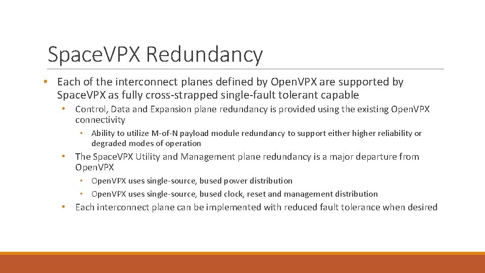
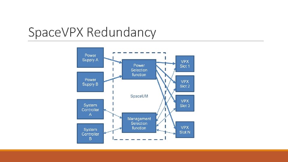
Space. VPX Redundancy • Each of the interconnect planes defined by Open. VPX are supported by Space. VPX as fully cross-strapped single-fault tolerant capable • Control, Data and Expansion plane redundancy is provided using the existing Open. VPX connectivity • Ability to utilize M-of-N payload module redundancy to support either higher reliability or degraded modes of operation • The Space. VPX Utility and Management plane redundancy is a major departure from Open. VPX • Open. VPX uses single-source, bused power distribution • Open. VPX uses single-source, bused clock, reset and management distribution • Each interconnect plane can be implemented with reduced fault tolerance when desired
Space. VPX Redundancy
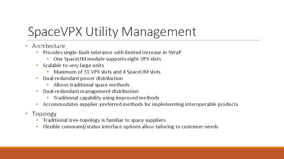
Space. VPX Utility Management • Architecture • Provides single-fault-tolerance with limited increase in SWa. P • One Space. UM module supports eight VPX slots • Scalable to very large units • Maximum of 31 VPX slots and 4 Space. UM slots • Dual-redundant power distribution • Allows traditional space methods • Dual-redundant management distribution • Traditional capability using improved methods • Accommodates supplier-preferred methods for implementing interoperable products • Topology • Traditional tree-topology is familiar to space suppliers • Flexible command/status interface options allow tailoring to customer needs
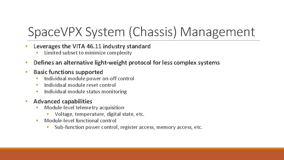
Space. VPX System (Chassis) Management • Leverages the VITA 46. 11 industry standard • Limited subset to minimize complexity • Defines an alternative light-weight protocol for less complex systems • Basic functions supported • • • Individual module power on-off control Individual module reset control Individual module status monitoring • Advanced capabilities • • Module-level telemetry acquisition • Voltage, temperature, digital state, etc. Module-level functional control • Sub-function power control, register access, memory access, etc.
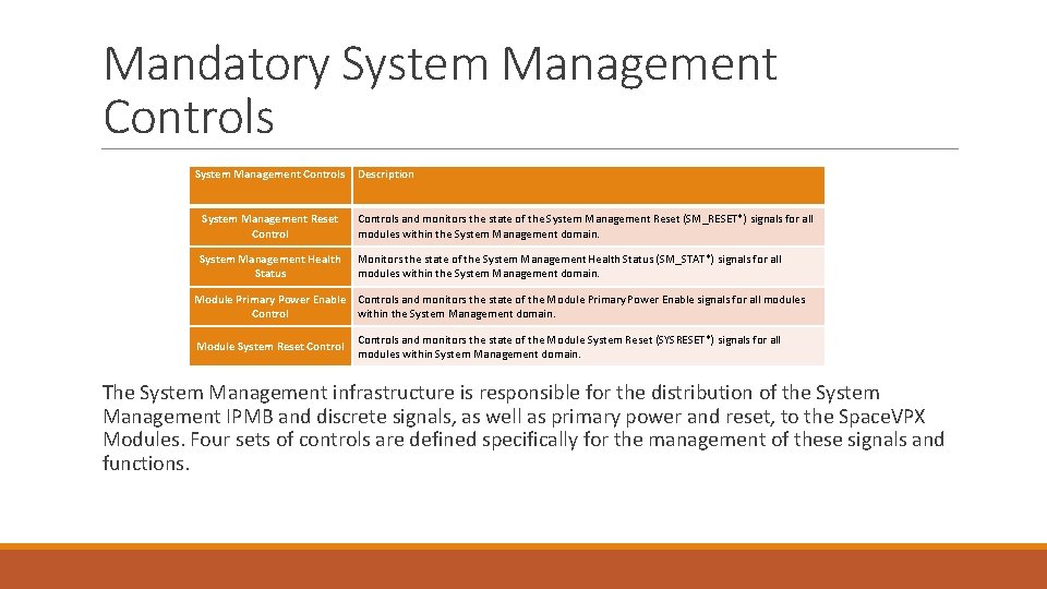
Mandatory System Management Controls Description System Management Reset Controls and monitors the state of the System Management Reset (SM_RESET*) signals for all modules within the System Management domain. System Management Health Status Monitors the state of the System Management Health Status (SM_STAT*) signals for all modules within the System Management domain. Module Primary Power Enable Controls and monitors the state of the Module Primary Power Enable signals for all modules Control within the System Management domain. Module System Reset Controls and monitors the state of the Module System Reset (SYSRESET*) signals for all modules within System Management domain. The System Management infrastructure is responsible for the distribution of the System Management IPMB and discrete signals, as well as primary power and reset, to the Space. VPX Modules. Four sets of controls are defined specifically for the management of these signals and functions.
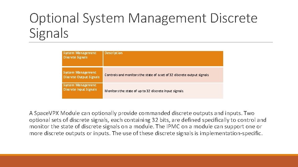
Optional System Management Discrete Signals System Management Discrete Output Signals System Management Discrete Input Signals Description Controls and monitors the state of a set of 32 discrete output signals. Monitors the state of up to 32 discrete input signals. A Space. VPX Module can optionally provide commanded discrete outputs and inputs. Two optional sets of discrete signals, each containing 32 bits, are defined specifically to control and monitor the state of discrete signals on a module. The IPMC on a module can support one or more discrete outputs or inputs. The use of these discrete signals is implementation-specific.
System Controller/Utility Plane
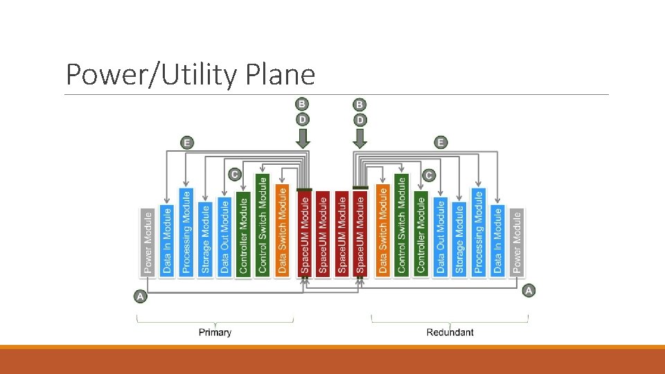
Space Utility-Management (Space. UM) Module Architecture • The Space. VPX Space. UM module provides selection functions for the dual-redundant Utility Plane (power) distribution and for the dual-redundant Utility Plane system control distribution. • By combining the Power Selection and Management Selection functions in the Space. UM module, Space. VPX provides compatibility with existing Open. VPX capabilities and implementations. • Note that although the Space. UM module is an integral part of the Space. VPX power distribution system, it is not a power supply and does not include transformer-coupled power isolation capability. • Note: Implementers that choose to provide power isolation in the Space. UM module are exceeding the scope of this specification.
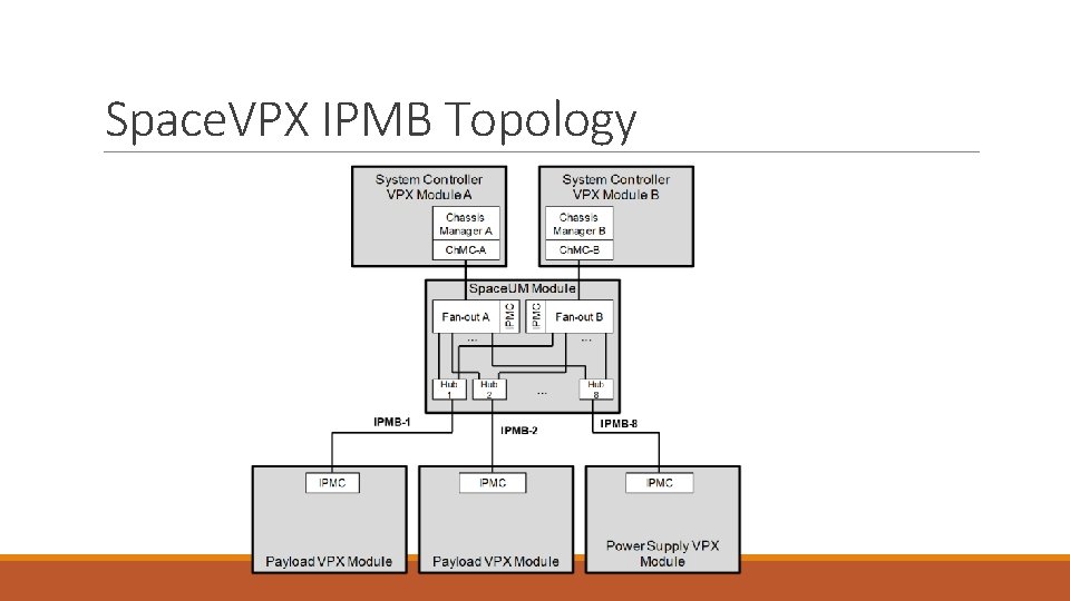
SYS_RST System Management System Controller B VPX Slot (Ch. MC) Select Circuit VPX Slot (IPMC) Select Circuit Management Fanout B (IPMC) Select (discrete) Select Circuit Controller Select Circuit VPX Slot (IPMC) Select Circuit Management Fanout A (IPMC) Select Circuit System Controller A VPX Slot (Ch. MC) Select Circuit SYS_RST System Management VPX Slot (IPMC) Space. VPX Management Distribution Topology
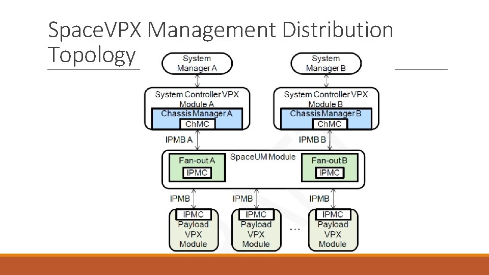
Space. VPX Management Distribution Topology
Space. VPX IPMB Topology
Power/Utility Plane
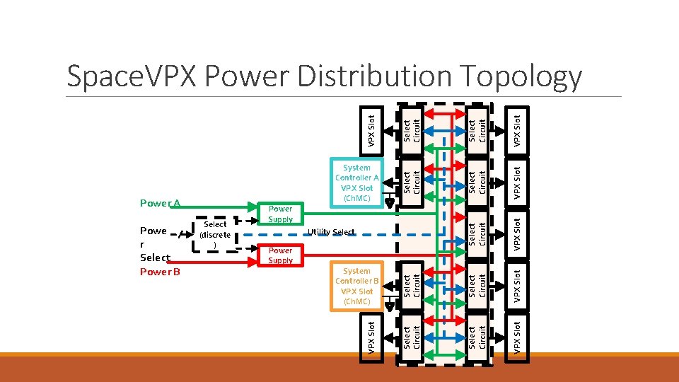
Select Circuit VPX Slot System Controller B VPX Slot (Ch. MC) Select Circuit VPX Slot Power Supply VPX Slot Select Circuit Utility Select Circuit Select (discrete ) Select Circuit Powe r Select Power B Power Supply VPX Slot Power A Select Circuit System Controller A VPX Slot (Ch. MC) Select Circuit VPX Slot Space. VPX Power Distribution Topology
Power Supply-Switch Module Profiles • The Space. VPX Power Supply-Switch module includes transformer-coupled power isolation capability between the Front Panel main power input and the secondary power outputs. • The secondary output power switching capability supports dual-redundant Space. VPX Utility Plane power distribution and allows the individual VPX slot power management needed for Space. VPX redundancy management. • By incorporating these functions, the Power Supply-Switch module provides compatibility with existing Open. VPX capabilities and implementations. • Space. VPX Power Supply-Switch modules are intended for use in redundant configurations where one module of the redundant set is active and all others are inactive. • The fault-tolerant POWER_SEL[5. . 0] signals are used to inform each Power Supply-Switch module of its current state (active or inactive). • System integrators are responsible for distributing the Power Select signals to the Power Supply. Switch modules in a manner that provides the desired redundancy control and fault tolerance.
Outline • What is Space. VPX? • Space. VPX Use Cases and Topologies • Space. VPX Slot Profiles • Space. VPX Backplane Profile • Space. UM - Provisions for Redundancy and Fault Tolerance • Space. VPX Mechanical General Specifications • Space. VPX Compliance • Backup
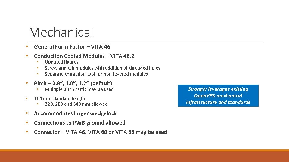
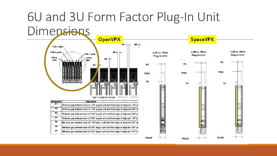
Mechanical • General Form Factor – VITA 46 • Conduction Cooled Modules – VITA 48. 2 • • • Updated figures Screw and tab modules with addition of threaded holes Separate extraction tool for non-levered modules • Pitch – 0. 8”, 1. 0”, 1. 2” (default) • • Multiple pitch cards may be used 160 mm standard length • 220, 280 and 340 mm allowed • Accommodates larger wedgelock • Connections to PWB ground allowed • Connector – VITA 46, VITA 60 or VITA 63 may be used Strongly leverages existing Open. VPX mechanical infrastructure and standards
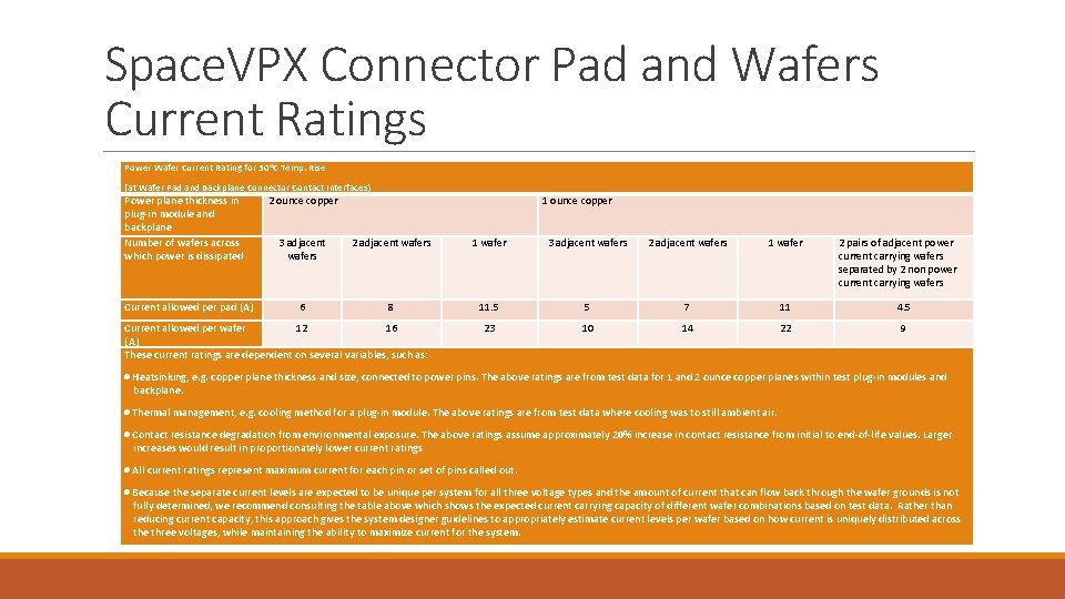
Space. VPX Connector Pad and Wafers Current Ratings Power Wafer Current Rating for 30 o. C Temp. Rise (at Wafer Pad and Backplane Connector Contact Interfaces) Power plane thickness in plug-in module and backplane Number of wafers across which power is dissipated Current allowed per pad (A) 2 ounce copper 1 ounce copper 3 adjacent wafers 2 adjacent wafers 1 wafer 6 8 11. 5 5 7 11 4. 5 23 10 14 22 9 Current allowed per wafer 12 16 (A) These current ratings are dependent on several variables, such as: 2 pairs of adjacent power current carrying wafers separated by 2 non power current carrying wafers Heatsinking, e. g. copper plane thickness and size, connected to power pins. The above ratings are from test data for 1 and 2 ounce copper planes within test plug-in modules and backplane. Thermal management, e. g. cooling method for a plug-in module. The above ratings are from test data where cooling was to still ambient air. Contact resistance degradation from environmental exposure. The above ratings assume approximately 20% increase in contact resistance from initial to end-of-life values. Larger increases would result in proportionately lower current ratings All current ratings represent maximum current for each pin or set of pins called out. Because the separate current levels are expected to be unique per system for all three voltage types and the amount of current that can flow back through the wafer grounds is not fully determined, we recommend consulting the table above which shows the expected current carrying capacity of different wafer combinations based on test data. Rather than reducing current capacity, this approach gives the system designer guidelines to appropriately estimate current levels per wafer based on how current is uniquely distributed across the three voltages, while maintaining the ability to maximize current for the system.
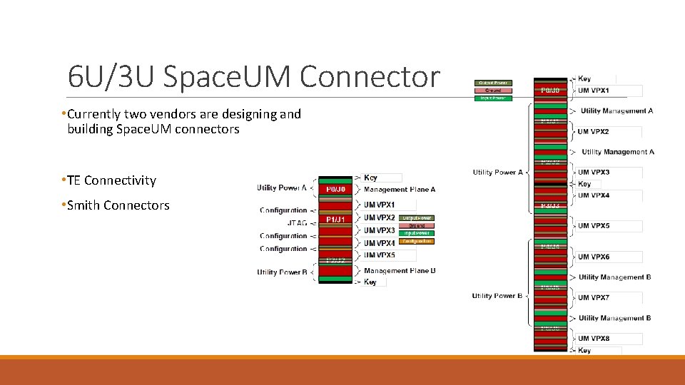
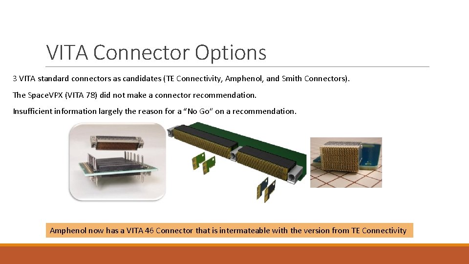
6 U/3 U Space. UM Connector • Currently two vendors are designing and building Space. UM connectors • TE Connectivity • Smith Connectors
6 U and 3 U Form Factor Plug-In Unit Dimensions Open. VPX Space. VPX
VITA Connector Options 3 VITA standard connectors as candidates (TE Connectivity, Amphenol, and Smith Connectors). The Space. VPX (VITA 78) did not make a connector recommendation. Insufficient information largely the reason for a “No Go” on a recommendation. Amphenol now has a VITA 46 Connector that is intermateable with the version from TE Connectivity
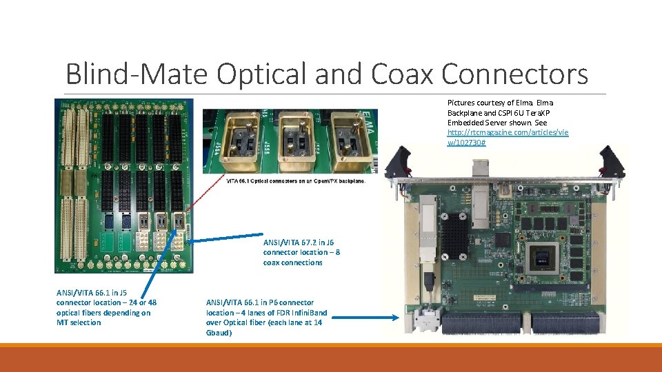
Blind-Mate Optical and Coax Connectors Pictures courtesy of Elma Backplane and CSPI 6 U Tera. XP Embedded Server shown. See http: //rtcmagazine. com/articles/vie w/102730# ANSI/VITA 67. 2 in J 6 connector location – 8 coax connections ANSI/VITA 66. 1 in J 5 connector location – 24 or 48 optical fibers depending on MT selection ANSI/VITA 66. 1 in P 6 connector location – 4 lanes of FDR Infini. Band over Optical fiber (each lane at 14 Gbaud)
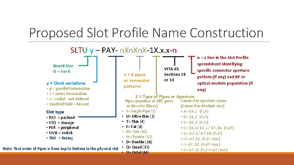
Proposed Slot Profile Name Construction SLTU y – PAY- n. Xn. X-1 X. x. x-n Board Size U = 3 or 6 y = Clock variations • p = parallel termination • s = series termination • x = radial - not defined • Omitted field = bussed • • • PAY = payload • • STO = storage • • PER = peripheral • • SWH = switch • • TIM = timing • Note: That order of Pipes is from top to bottom in the physical slot • • Slot type n = # pipes or connector patterns VITA 65 Sections 10 or 14 n = a line in the Slot Profile spreadsheet identifying specific connector aperture pattern (if any) and RF or optical module population (if any) X = Type of Pipes or Aperture Pipes (number of diff. pairs or discrete fibers) S= Single Pipe (1) U= Ultra-thin (2) T= Thin (4) F= Fat (8) M= Ten (10) W=Twelve (12) D= Double (16) Q= Quad (32) O= Octal (64) Connector aperture name (Connector Module size) • A= 66. 1 (full) • B= 66. 2 (full) • C= 66. 3 (full) • E= 66. 4/ 67. 1/ 67. 3 A (half) • G= 67. 2/ 67. 3 B (full) • H= 67. 3 C (full new) • J= 67. 3 D (half new) • K= 67. 3 E (full+half new)
Outline • What is Space. VPX? • Space. VPX Use Cases and Topologies • Space. VPX Slot Profiles • Space. VPX Backplane Profile • Space. UM - Provisions for Redundancy and Fault Tolerance • Space. VPX Mechanical General Specifications • Space. VPX Compliance • Backup
Space. VPX Compliance Space. VPX standards enable the creation of robust high performance space electronics systems. Space. VPX standardizes the interfaces necessary for developing and integrating interoperable standard electronics modules leveraging the [VITA 65] family of standards. There are many levels of user definition while maintaining the base capabilities needed for such systems. Space. VPX provides for the following levels of compliance and compatibility. • A Space. VPX compliant module meets the module requirements of Section 8 and Section 12 (6 U) or Section 16 (3 U). • A Space. VPX compliant development chassis meets the development chassis requirements of Section 9 and Section 13 (6 U) or Section 17 (3 U). • A Space. VPX compliant backplane meets the backplane requirements of Section 7 and Section 11 (6 U) or Section 15 (3 U). • Permission 2 -1: Compliant backplane implementations based on an included topology may be reduced by any number of slot types and/or increased by any number of peripheral slots, as long as single-fault tolerance requirements are maintained.
Space. VPX Compliance (2) A Space. VPX compatible backplane meets the backplane requirements of a Space. VPX compliant backplane while allowing the absence of spares (redundant modules) and/or Space. UM modules. A Space. VPX compatible module is any module that operates without causing damage to itself or other Space. VPX elements when plugged into a Space. VPX slot as defined in Section 6 and Section 10 (6 U) or Section 14 (3 U) contained within a Space. VPX backplane as defined in Section 7 and Section 11 (6 U) or Section 15 (3 U). Any Open. VPX module not modified to be compliant with the Space. VPX standard is Space. VPX compatible if it meets the requirements for a Space. VPX compatible module. A fully compliant fault tolerant Space. VPX system provides at least single fault tolerant capabilities throughout. • Permission 2 2: Based on the system reliability requirements, modules may be combined or attached. • Rule 2 -2: Single point fault tolerance shall be achieved between each redundancy grouping as well as on all intergroup interfaces. Such a system typically includes a Space. VPX compliant chassis, a Space. VPX compliant backplane, one to four Space. UM modules and two or more Space. VPX compliant and/or compatible modules.
New Efforts
Spac. VNX (VITA 74. 4)
The Story Behind VNX is a standards based, small form factor, ecosystem and infrastructure ◦ VITA-74 Committee est. by VITA Standards Organization(VSO) in early 2010 ◦ The VITA-74 Committee has significant involvement from several merchant board manufacturers, system integrators, and defense primes ◦ The Standard’s status is “Released for Trial Use” and is gaining wide acceptance ◦ VNX Marketing Committee established by VSO in early 2014 VNX used existing standards to reduce technical risk and schedule ◦ VITA-46 VPX and VITA-65 Open VPX topology and pin assignments ◦ VITA-57 FMC connector ◦ PICMG COM Express Mini SBC VNX committee provides reference chassis design in the spec. ◦ 12. 5 mm and 19 mm Modules ◦ 4 -Slot cubical chassis
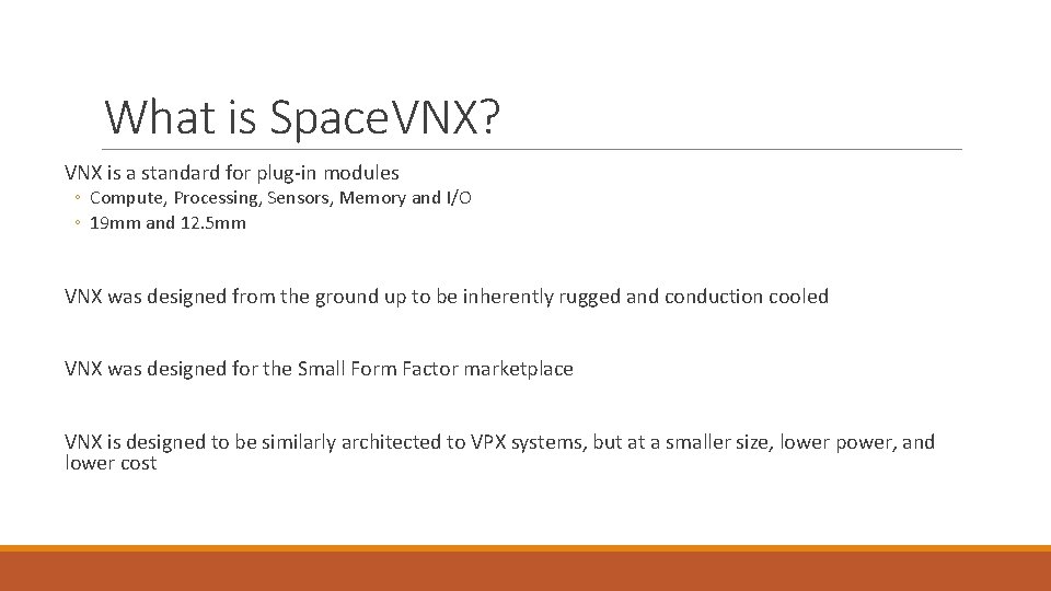
What is Space. VNX? VNX is a standard for plug-in modules ◦ Compute, Processing, Sensors, Memory and I/O ◦ 19 mm and 12. 5 mm VNX was designed from the ground up to be inherently rugged and conduction cooled VNX was designed for the Small Form Factor marketplace VNX is designed to be similarly architected to VPX systems, but at a smaller size, lower power, and lower cost
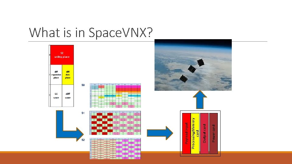
Power card Output card Processing/Memory card Payload input What is in Space. VNX?
Value Proposition Small satellite benefits ◦ Lower overall cost to an operational system. ◦ Disaggregation allows for greater system resiliency and redundancy ◦ System would become “single-point failure” tolerant through redundant power distribution and fault detection on critical configuration signals Small Satellite Standards Development ◦ Increased market potential and vendor competition for user needs Adoption of VITA 74 ◦ ◦ ◦ A marketed reduction in CSWa. P of rugged embedded computer systems Concurrent increase in architectural modularity Provision of higher performance computing capability in a smaller form factor Optional implementation of PCIe Ring Topology Robust system diagnostics
Space. VNX Use Cases I. Single small satellite high performance computing (data collection and data analytics) capability at a lower cost. II. Single small satellite networked high performance computing platform with a large data collection and processing capability. III. Disaggregated cluster of networked satellites designed for a variety of data collection and data analysis applications with a single sensor. IV. Disaggregated cluster of network satellites designed for variety of data collection and data analysis applications with multiple sensors, where the networked cluster fuses the data from all active sensors.
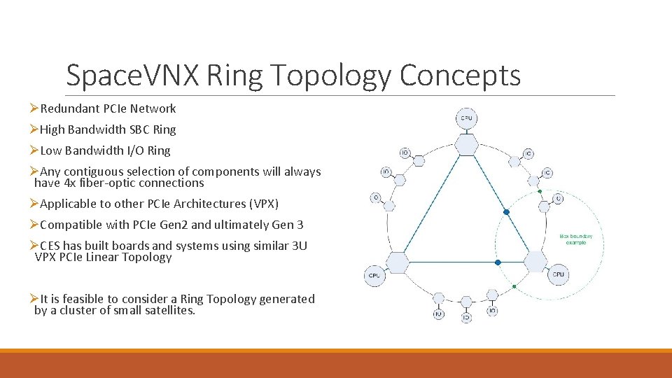
Space. VNX Ring Topology Concepts ØRedundant PCIe Network ØHigh Bandwidth SBC Ring ØLow Bandwidth I/O Ring ØAny contiguous selection of components will always have 4 x fiber-optic connections ØApplicable to other PCIe Architectures (VPX) ØCompatible with PCIe Gen 2 and ultimately Gen 3 ØCES has built boards and systems using similar 3 U VPX PCIe Linear Topology ØIt is feasible to consider a Ring Topology generated by a cluster of small satellites.
Questions?
Backup