MSI MicroStar International 1 ACPI Advanced Configuration and



- Slides: 61
MSI Micro-Star International 1
ACPI Advanced Configuration and Power Interface Reporter : Wequalwu 2
Contents ACPI Overview v ASL (ACPI Source Language) v ACPI Implementer in AWARD BIOS v 3
History of Power Management SL technology - 1989 First seen on the 386 SL and still included in all of today’s Pentium and Pentium II processors Operating system had no idea of what the power management BIOS was up to. Advanced Power Management - 1991 Intel & Microsoft co-developed OS and power management BIOS could now talk to each other No cooperation among system components Add-on components do not participate in power management ACPI (Advanced Configuration and Power Interface) - 1997 Intel, Toshiba and Microsoft Open industry, all encompassing, PC hardware, operating system and peripheral device interface specifications Primary goal is to let O. S. manage all power activity 4
ACPI Introduction 1. industry common interfaces 2. The key element in Operating System-directed configuration and Power Management (OSPM). 3. stretch the limits of current Plug and Play interfaces. 4. more robust, and potentially more efficient manner. 5. collection of power management BIOS code, Advanced Power Management (APM) application programming interfaces (APIs, PNPBIOS APIs, Multiprocessor Specification (MPS) 6. suitable to all classes of computers including (but not limited to) desktop, mobile, workstation, and server machines 5
Principal Goals 1. ACPI provides OSPM with direct and exclusive control over the power management and motherboard device configuration functions of a computer. OS plays a central role and uses global information to optimize system behavior. ACPI is the key element in OSPM 2. Enable all computer systems to implement motherboard configuration and power management functions 3. Enhance power management functionality and robustness. 4. Facilitate and accelerate industry-wide implementation of power management. 5. Create a robust interface for configuring motherboard devices. 6
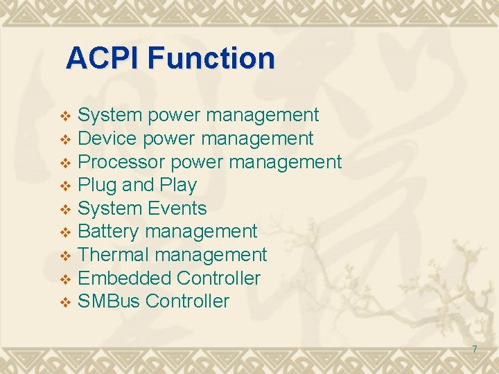
ACPI Function System power management v Device power management v Processor power management v Plug and Play v System Events v Battery management v Thermal management v Embedded Controller v SMBus Controller v 7
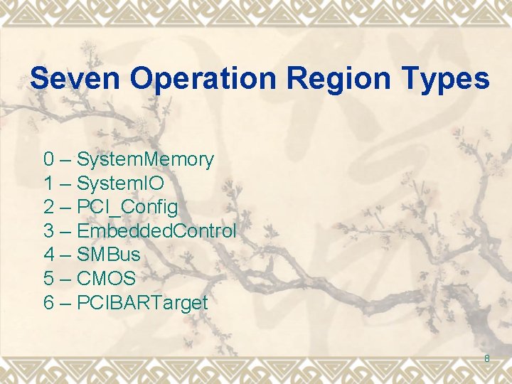
Seven Operation Region Types 0 – System. Memory 1 – System. IO 2 – PCI_Config 3 – Embedded. Control 4 – SMBus 5 – CMOS 6 – PCIBARTarget 8
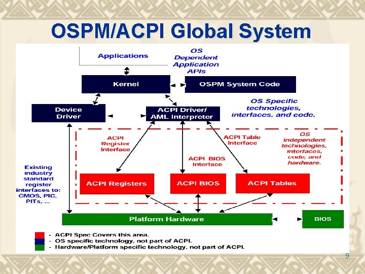
OSPM/ACPI Global System 9
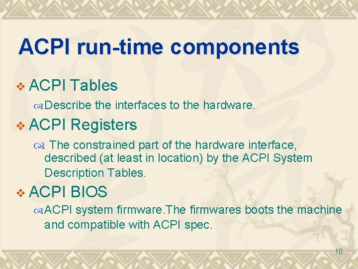
ACPI run-time components v ACPI Tables Describe the interfaces to the hardware. v ACPI Registers The constrained part of the hardware interface, described (at least in location) by the ACPI System Description Tables. v ACPI BIOS ACPI system firmware. The firmwares boots the machine and compatible with ACPI spec. 10
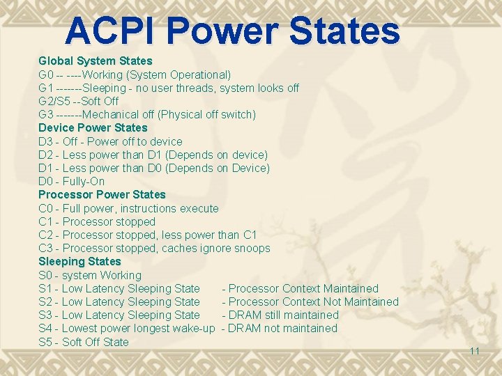
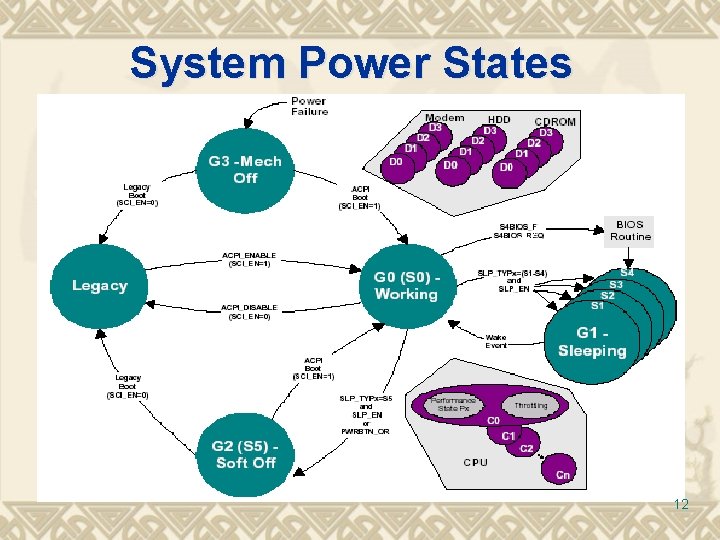
ACPI Power States Global System States G 0 -- ----Working (System Operational) G 1 -------Sleeping - no user threads, system looks off G 2/S 5 --Soft Off G 3 -------Mechanical off (Physical off switch) Device Power States D 3 - Off - Power off to device D 2 - Less power than D 1 (Depends on device) D 1 - Less power than D 0 (Depends on Device) D 0 - Fully-On Processor Power States C 0 - Full power, instructions execute C 1 - Processor stopped C 2 - Processor stopped, less power than C 1 C 3 - Processor stopped, caches ignore snoops Sleeping States S 0 - system Working S 1 - Low Latency Sleeping State - Processor Context Maintained S 2 - Low Latency Sleeping State - Processor Context Not Maintained S 3 - Low Latency Sleeping State - DRAM still maintained S 4 - Lowest power longest wake-up - DRAM not maintained S 5 - Soft Off State 11
System Power States 12
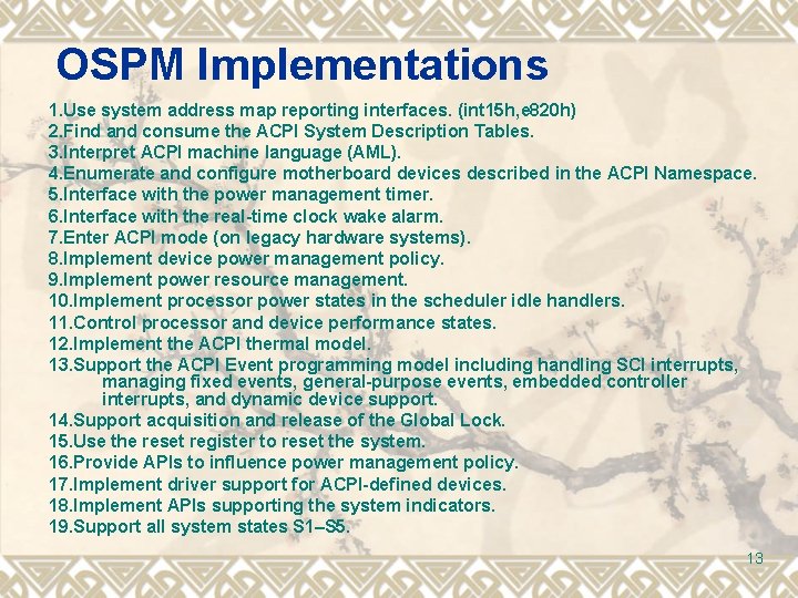
OSPM Implementations 1. Use system address map reporting interfaces. (int 15 h, e 820 h) 2. Find and consume the ACPI System Description Tables. 3. Interpret ACPI machine language (AML). 4. Enumerate and configure motherboard devices described in the ACPI Namespace. 5. Interface with the power management timer. 6. Interface with the real-time clock wake alarm. 7. Enter ACPI mode (on legacy hardware systems). 8. Implement device power management policy. 9. Implement power resource management. 10. Implement processor power states in the scheduler idle handlers. 11. Control processor and device performance states. 12. Implement the ACPI thermal model. 13. Support the ACPI Event programming model including handling SCI interrupts, managing fixed events, general-purpose events, embedded controller interrupts, and dynamic device support. 14. Support acquisition and release of the Global Lock. 15. Use the reset register to reset the system. 16. Provide APIs to influence power management policy. 17. Implement driver support for ACPI-defined devices. 18. Implement APIs supporting the system indicators. 19. Support all system states S 1–S 5. 13
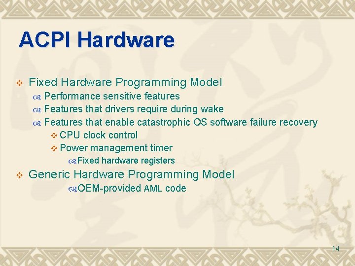
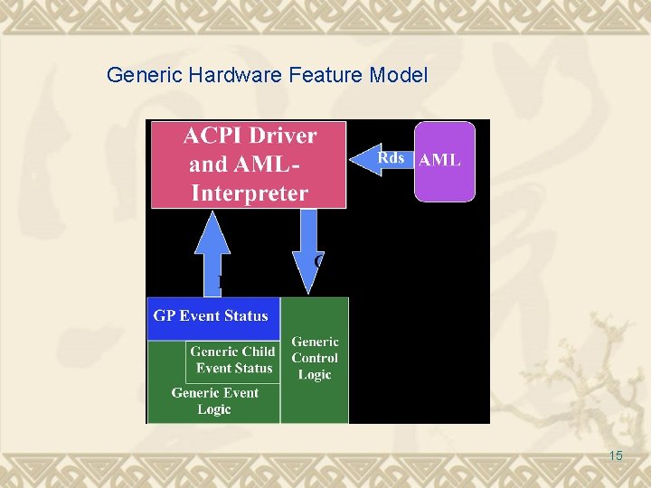
ACPI Hardware v Fixed Hardware Programming Model Performance sensitive features Features that drivers require during wake Features that enable catastrophic OS software failure recovery v CPU clock control v Power management timer Fixed hardware registers v Generic Hardware Programming Model OEM-provided AML code 14
Generic Hardware Feature Model 15
Global States and Their Transitions 16
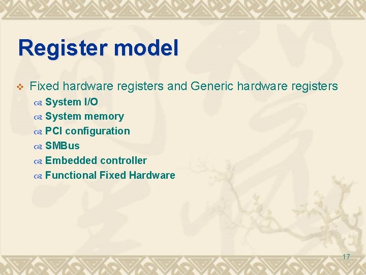
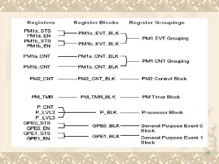
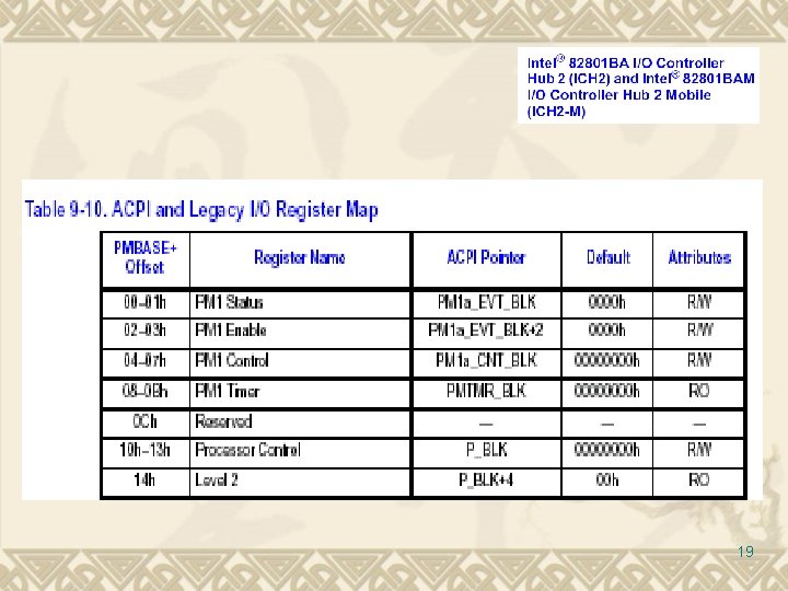
Register model v Fixed hardware registers and Generic hardware registers System I/O System memory PCI configuration SMBus Embedded controller Functional Fixed Hardware 17
18
19
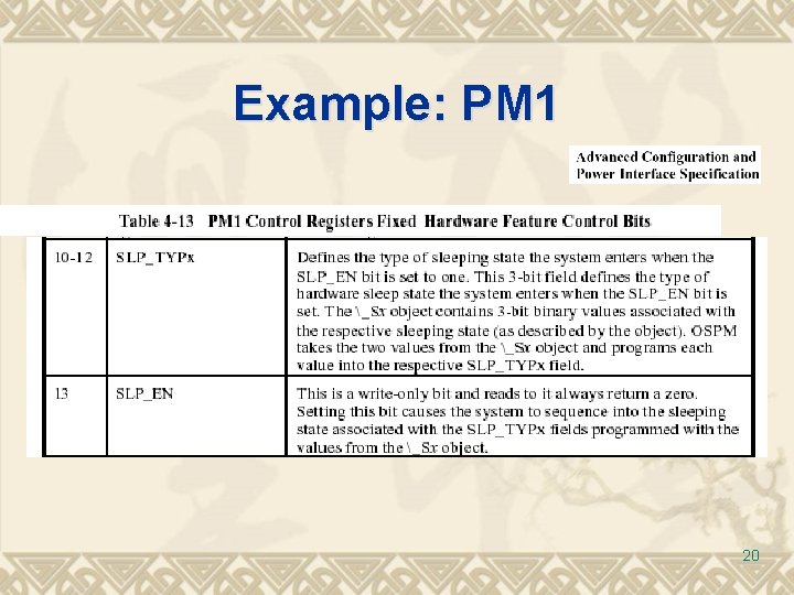
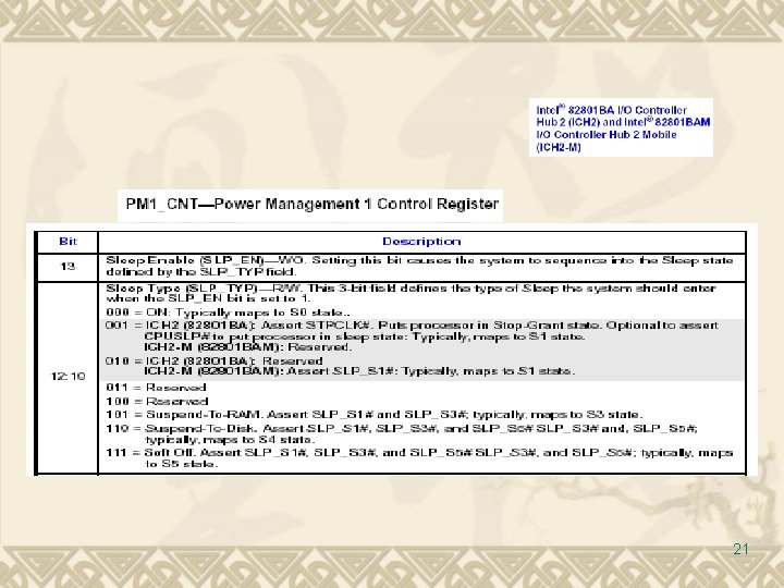
Example: PM 1 20
21
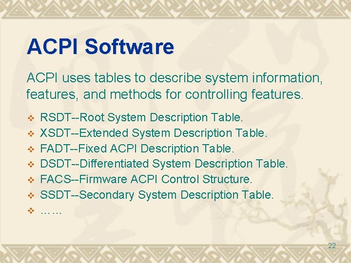
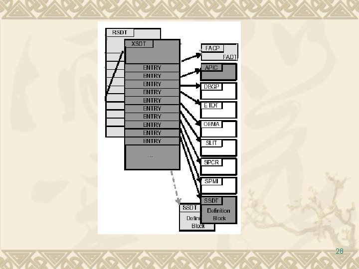
ACPI Software ACPI uses tables to describe system information, features, and methods for controlling features. v v v v RSDT--Root System Description Table. XSDT--Extended System Description Table. FADT--Fixed ACPI Description Table. DSDT--Differentiated System Description Table. FACS--Firmware ACPI Control Structure. SSDT--Secondary System Description Table. …… 22
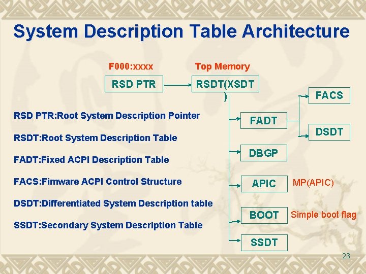
System Description Table Architecture F 000: xxxx RSD PTR Top Memory RSDT(XSDT ) RSD PTR: Root System Description Pointer FADT DSDT RSDT: Root System Description Table FADT: Fixed ACPI Description Table FACS: Fimware ACPI Control Structure FACS DBGP APIC MP(APIC) BOOT Simple boot flag DSDT: Differentiated System Description table SSDT: Secondary System Description Table SSDT 23
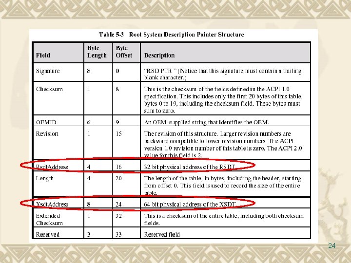
24
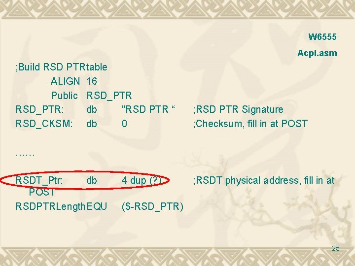
W 6555 Acpi. asm ; Build RSD PTRtable ALIGN 16 Public RSD_PTR: db "RSD PTR “ RSD_CKSM: db 0 ; RSD PTR Signature ; Checksum, fill in at POST …… RSDT_Ptr: db POST RSDPTRLength. EQU 4 dup (? ) ; RSDT physical address, fill in at ($-RSD_PTR) 25
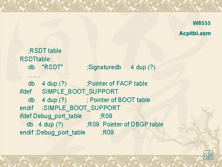
W 6555 Acpitbl. asm ; RSDT table RSDTtable: db "RSDT" ; Signaturedb 4 dup (? ) …… db 4 dup (? ) ; Pointer of FACP table ifdef SIMPLE_BOOT_SUPPORT db 4 dup (? ) ; Pointer of BOOT table endif ; SIMPLE_BOOT_SUPPORT ifdef Debug_port_table ; R 09 db 4 dup (? ) ; R 09 Pointer of DBGP table endif ; Debug_port_table ; R 09 27
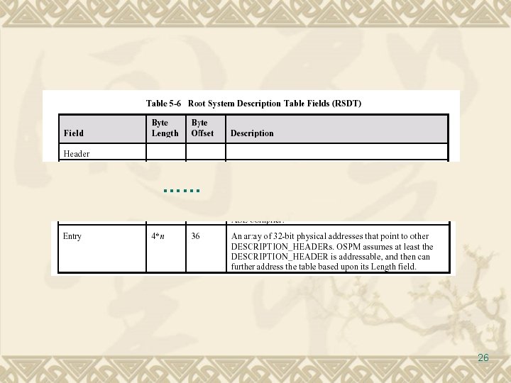
28
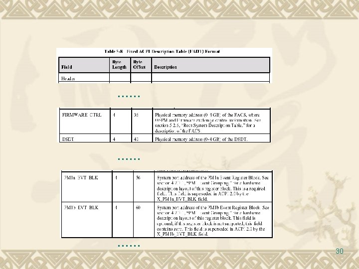
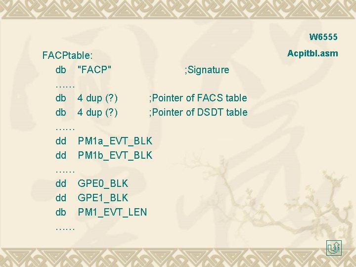
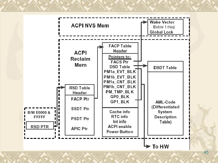
Fixed ACPI Description Table (FADT) FADT defines various fixed hardware ACPI information vital to an ACPI-compatible OS, such as the base address for the following hardware registers blocks: PM 1 a_EVT_BLK, PM 1 b_EVT_BLK, PM 1 a_CNT_BLK, PM 1 b_CNT_BLK…… 29
W 6555 FACPtable: db "FACP" ; Signature …… db 4 dup (? ) ; Pointer of FACS table db 4 dup (? ) ; Pointer of DSDT table …… dd PM 1 a_EVT_BLK dd PM 1 b_EVT_BLK …… dd GPE 0_BLK dd GPE 1_BLK db PM 1_EVT_LEN …… Acpitbl. asm 31
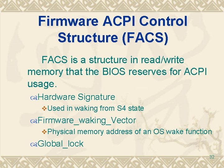
Firmware ACPI Control Structure (FACS) FACS is a structure in read/write memory that the BIOS reserves for ACPI usage. Hardware Signature v. Used in waking from S 4 state Firmware_waking_Vector v. Physical memory address of an OS wake function Global_lock 32
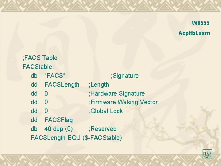
W 6555 Acpitbl. asm ; FACS Table FACStable: db "FACS" ; Signature dd FACSLength ; Length dd 0 ; Hardware Signature dd 0 ; Firmware Waking Vector dd 0 ; Global Lock dd FACSFlag db 40 dup (0) ; Reserved FACSLength EQU ($-FACStable) 33
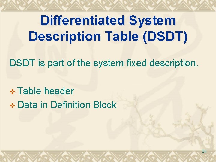
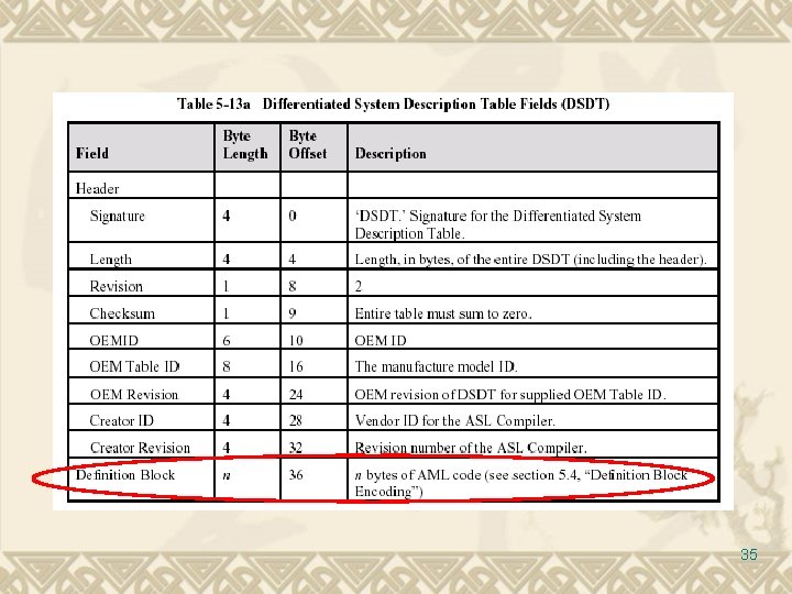
Differentiated System Description Table (DSDT) DSDT is part of the system fixed description. v Table header v Data in Definition Block 34
35
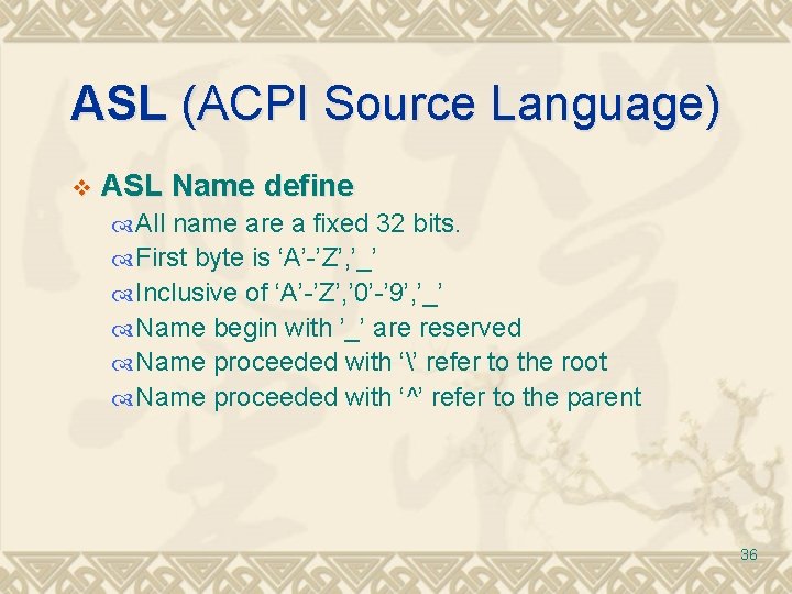
ASL (ACPI Source Language) v ASL Name define All name are a fixed 32 bits. First byte is ‘A’-’Z’, ’_’ Inclusive of ‘A’-’Z’, ’ 0’-’ 9’, ’_’ Name begin with ’_’ are reserved Name proceeded with ‘’ refer to the root Name proceeded with ‘^’ refer to the parent 36
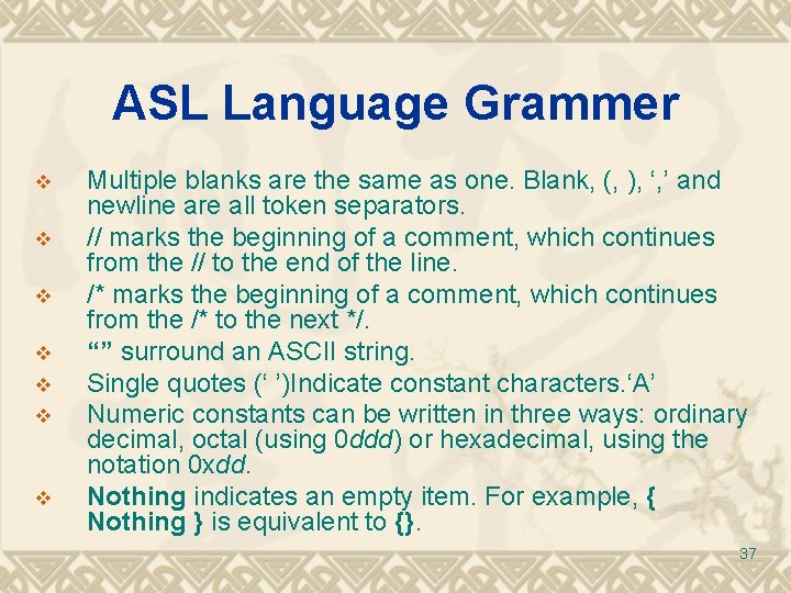
ASL Language Grammer v v v v Multiple blanks are the same as one. Blank, (, ), ‘, ’ and newline are all token separators. // marks the beginning of a comment, which continues from the // to the end of the line. /* marks the beginning of a comment, which continues from the /* to the next */. “” surround an ASCII string. Single quotes (‘ ’)Indicate constant characters. ‘A’ Numeric constants can be written in three ways: ordinary decimal, octal (using 0 ddd) or hexadecimal, using the notation 0 xdd. Nothing indicates an empty item. For example, { Nothing } is equivalent to {}. 37
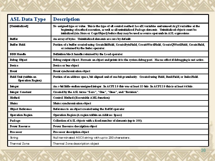
ASL Data Type Description [Uninitialized] No assigned type or value. This is the type of all control method Local. X variables and unused Arg. X variables at the beginning of method execution, as well as all uninitialized Package elements. Uninitialized objects must be initialized (via Store or Copy. Object) before they may be used as source operands in ASL expressions. Buffer An array of bytes. Uninitialized elements are zero by default. Buffer Field Portion of a buffer created using Create. Bit. Field, Create. Byte. Field, Create. Word. Field, Create. QWord. Field, Create. Field, or returned by the Index operator. DDB Handle Definition block handle returned by the Load operator Debug Object Debug output object. Formats an object and prints it to the system debug port. Has no effect if debugging is not active. Device or bus object Event synchronization object Field Unit (within an Operation Region) Portion of an address space, bit-aligned and of one-bit granularity. Created using Field, Bank. Field, or Index. Field. Integer An n-bit little-endian unsigned integer. In ACPI 1. 0 this was at least 32 -bits. In ACPI 2. 0 this is at least 64. bits. Integer Constant Created by the ASL terms “Zero”, “Ones”, and “Revision”. Method Control Method (Executable AML function) Mutex synchronization object Object Reference to an object created using the Ref. Of operator Operation Region (A region within an Address Space) Package Collection of ASL objects with a fixed number of elements (up to 255). Power Resource description object Processor description object String Null-terminated ASCII string with up to 200 characters. Thermal Zone description object 38
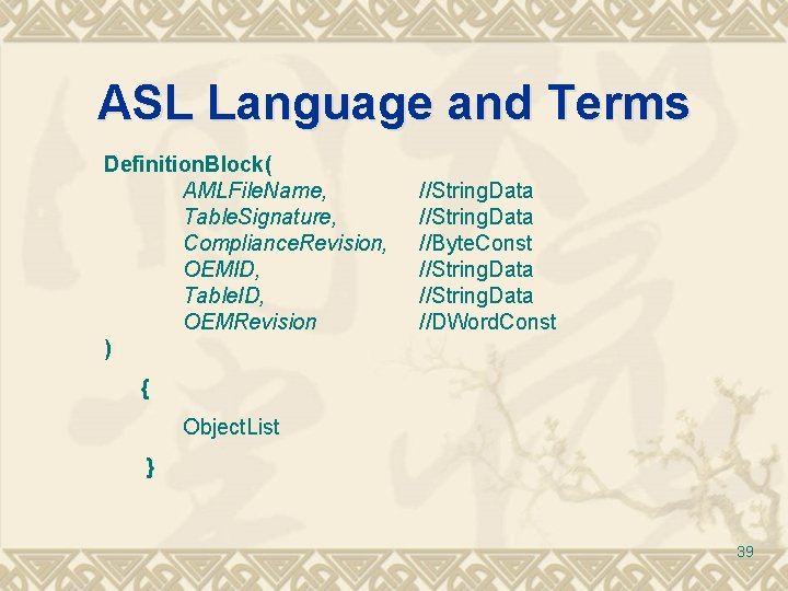
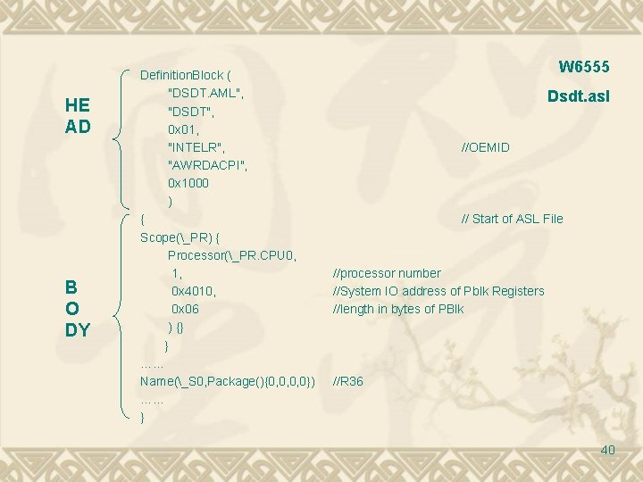
ASL Language and Terms Definition. Block( AMLFile. Name, Table. Signature, Compliance. Revision, OEMID, Table. ID, OEMRevision ) //String. Data //Byte. Const //String. Data //DWord. Const { Object. List } 39
HE AD B O DY Definition. Block ( "DSDT. AML", "DSDT", 0 x 01, "INTELR", "AWRDACPI", 0 x 1000 ) { Scope(_PR) { Processor(_PR. CPU 0, 1, 0 x 4010, 0 x 06 ) {} } …… Name(_S 0, Package(){0, 0, 0, 0}) …… } W 6555 Dsdt. asl //OEMID // Start of ASL File //processor number //System IO address of Pblk Registers //length in bytes of PBlk //R 36 40
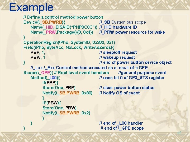
Example // Define a control method power button Device(_SB. PWRB){ //_SB System bus scope Name(_HID, EISAID(“PNP 0 C 0 C”)) //_HID hardware ID Name(_PRW, Package(){0, 0 x 4}) //_PRW power resource for wake } Operation. Region(Pho, System. IO, 0 x 200, 0 x 1) Field(Pho, Byte. Acc, No. Lock, Write. As. Zeros){ PBP, 1, // sleep/off request PBW, 1 // wakeup request } // end of power button device object //_Lxx /_Exx Control method executed as a result of a GPE Scope(_GPE){ // Root level event handlers //general-purpose event. Method(_L 00){ // uses bit 0 of GP 0_STS register If(PBP){ Store(One, PBP) // clear power button status Notify(_SB. PWRB, 0 x 80) // Notify OS of event } IF(PBW){ Store(One, PBW) Notify(_SB. PWRB, 0 x 2) } } // end of _L 00 handler } // end of _GPE scope 41
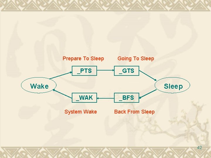
Prepare To Sleep _PTS Going To Sleep _GTS Wake Sleep _WAK System Wake _BFS Back From Sleep 42
ACPI In BIOS 43
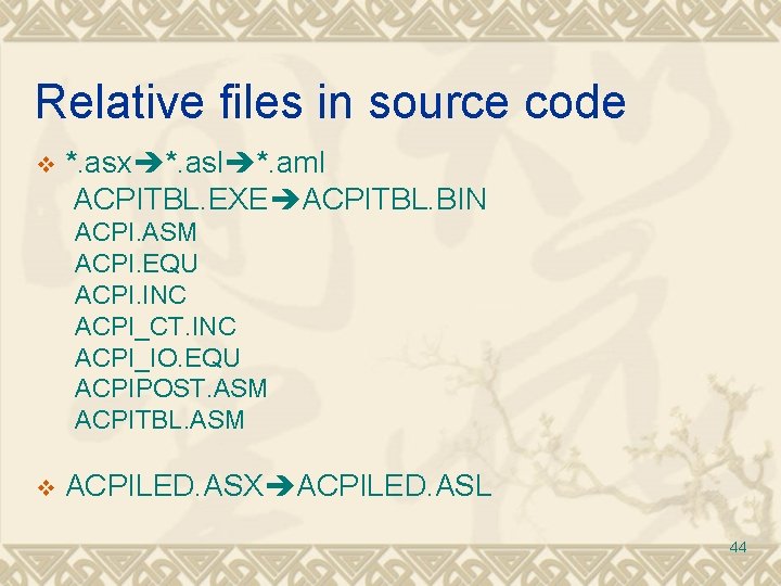
Relative files in source code v *. asx *. asl *. aml ACPITBL. EXE ACPITBL. BIN ACPI. ASM ACPI. EQU ACPI. INC ACPI_CT. INC ACPI_IO. EQU ACPIPOST. ASM ACPITBL. ASM v ACPILED. ASX ACPILED. ASL 44
45
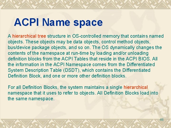
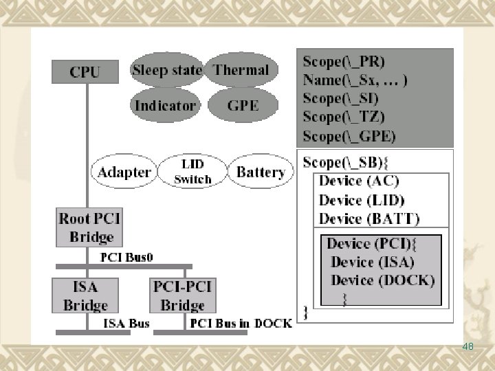
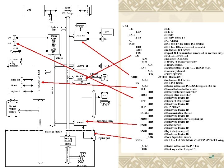
ACPI Name space A hierarchical tree structure in OS-controlled memory that contains named objects. These objects may be data objects, control method objects, bus/device package objects, and so on. The OS dynamically changes the contents of the namespace at run-time by loading and/or unloading definition blocks from the ACPI Tables that reside in the ACPI BIOS. All the information in the ACPI Namespace comes from the Differentiated System Description Table (DSDT), which contains the Differentiated Definition Block, and one or more other definition blocks. For all Definition Blocks, the system maintains a single hierarchical namespace that it uses to refer to objects. All Definition Blocks load into the same namespace. 46
Example ACPI Name. Space 47
48
49
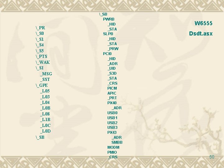
_PR _S 0 _S 1 _S 4 _S 5 _PTS _WAK _SI _MSG _SST _GPE _L 05 _L 03 _L 04 _L 0 B _L 08 _L 1 B _L 0 C _L 0 D _SB PWRB _HID _STA SLPB _HID _STA _PRW PCI 0 _HID _ADR _UID _S 3 D _STA _CRS PICM APIC _PRT PX 40 _ADR USB 0 USB 1 USB 2 USB 3 PX 43 _ADR SMBB MODM PMIO _CRS W 6555 Dsdt. asx 50
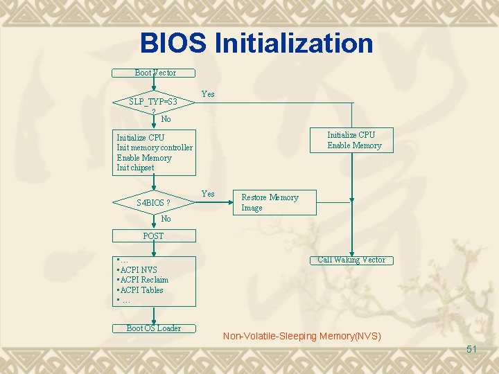
BIOS Initialization Boot Vector SLP_TYP=S 3 ? No Yes Initialize CPU Enable Memory Initialize CPU Init memory controller Enable Memory Init chipset S 4 BIOS ? Yes Restore Memory Image No POST • … • ACPI NVS • ACPI Reclaim • ACPI Tables • … Boot OS Loader Call Waking Vector Non-Volatile-Sleeping Memory(NVS) 51
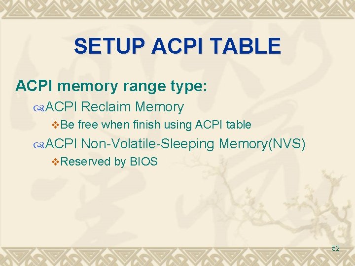
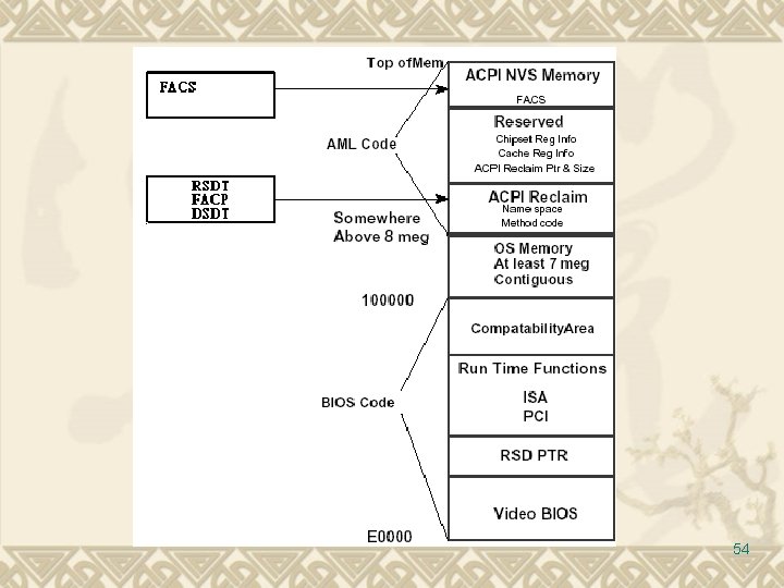
SETUP ACPI TABLE ACPI memory range type: ACPI Reclaim Memory v. Be free when finish using ACPI table ACPI Non-Volatile-Sleeping Memory(NVS) v. Reserved by BIOS 52
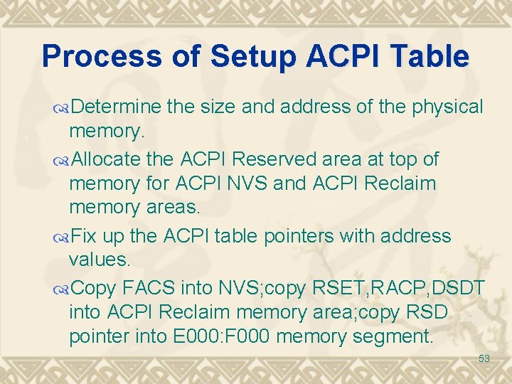
Process of Setup ACPI Table Determine the size and address of the physical memory. Allocate the ACPI Reserved area at top of memory for ACPI NVS and ACPI Reclaim memory areas. Fix up the ACPI table pointers with address values. Copy FACS into NVS; copy RSET, RACP, DSDT into ACPI Reclaim memory area; copy RSD pointer into E 000: F 000 memory segment. 53
54
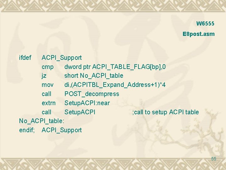
W 6555 E 8 post. asm ifdef ACPI_Support cmp dword ptr ACPI_TABLE_FLAG[bp], 0 jz short No_ACPI_table mov di, (ACPITBL_Expand_Address+1)*4 call POST_decompress extrn Setup. ACPI: near call Setup. ACPI ; call to setup ACPI table No_ACPI_table: endif; ACPI_Support 55
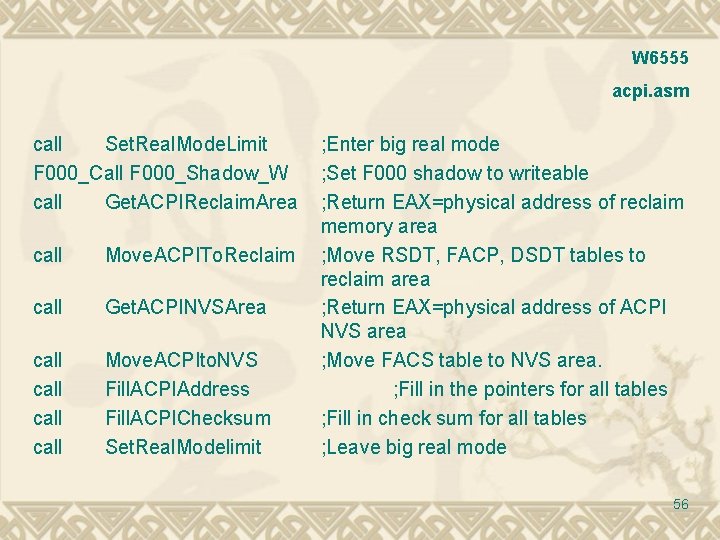
W 6555 acpi. asm call Set. Real. Mode. Limit F 000_Call F 000_Shadow_W call Get. ACPIReclaim. Area call Move. ACPITo. Reclaim call Get. ACPINVSArea call Move. ACPIto. NVS Fill. ACPIAddress Fill. ACPIChecksum Set. Real. Modelimit ; Enter big real mode ; Set F 000 shadow to writeable ; Return EAX=physical address of reclaim memory area ; Move RSDT, FACP, DSDT tables to reclaim area ; Return EAX=physical address of ACPI NVS area ; Move FACS table to NVS area. ; Fill in the pointers for all tables ; Fill in check sum for all tables ; Leave big real mode 56
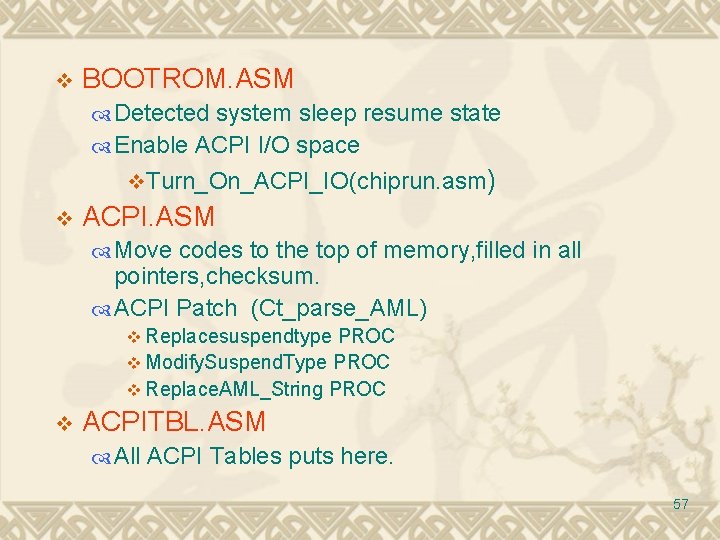
v BOOTROM. ASM Detected system sleep resume state Enable ACPI I/O space v. Turn_On_ACPI_IO(chiprun. asm) v ACPI. ASM Move codes to the top of memory, filled in all pointers, checksum. ACPI Patch (Ct_parse_AML) v Replacesuspendtype PROC v Modify. Suspend. Type PROC v Replace. AML_String PROC v ACPITBL. ASM All ACPI Tables puts here. 57
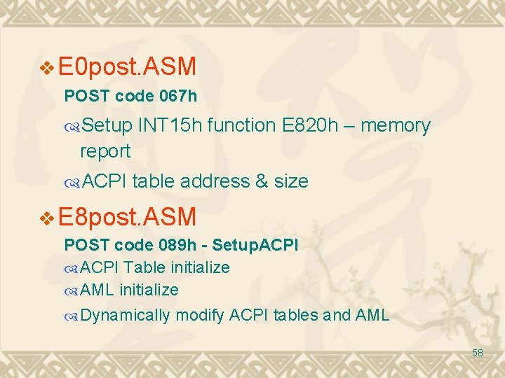
v E 0 post. ASM POST code 067 h Setup INT 15 h function E 820 h – memory report ACPI table address & size v E 8 post. ASM POST code 089 h - Setup. ACPI Table initialize AML initialize Dynamically modify ACPI tables and AML 58
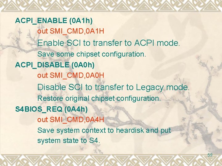
ACPI_ENABLE (0 A 1 h) out SMI_CMD, 0 A 1 H Enable SCI to transfer to ACPI mode. Save some chipset configuration. ACPI_DISABLE (0 A 0 h) out SMI_CMD, 0 A 0 H Disable SCI to transfer to Legacy mode. Restore original chipset configuration. S 4 BIOS_REQ (0 A 4 h) out SMI_CMD, 0 A 4 H Save system context to heardisk and put system state to S 4. 59
Questions v How does OS get SCI information? v Is ACPI table dynamical created by BIOS Post? v Can modify ACPI table in OS? 60
THE END Thank you 61