Limit Fit Tolerance Maximum and Minimum Metal Conditions


 Determination of tolerance: Tolerance on hole = HLH − LLH = 30. 02")
 Basic size is the same for both shaft and hole. (b) Determination of")
 Determination of clearances: Maximum clearance = HLH − LLS = 50. 02 −")
- Slides: 35
Limit Fit & Tolerance
Maximum and Minimum Metal Conditions ü Let us consider a shaft having a dimension of 40 ± 0. 05 mm. ü The maximum metal limit (MML) of the shaft will have a dimension of 40. 05 mm because at this higher limit, the shaft will have the maximum possible amount of metal. ü The shaft will have the least possible amount of metal at a lower limit of 39. 95 mm, and this limit of the shaft is known as minimum or least metal limit (LML). ü Similarly, consider a hole having a dimension of 45 ± 0. 05 mm. ü The hole will have a maximum possible amount of metal at a lower limit of 44. 95 mm and the lower limit of the hole is designated as MML. ü For example, when a hole is drilled in a component, minimum amount of material is removed at the lower limit size of the hole. This lower limit of the hole is known as MML. ü The higher limit of the hole will be the LML. At a high limit of 45. 05 mm, the hole will have the least possible amount of metal. ü The maximum and minimum metal conditions are shown in Fig. 3. 8
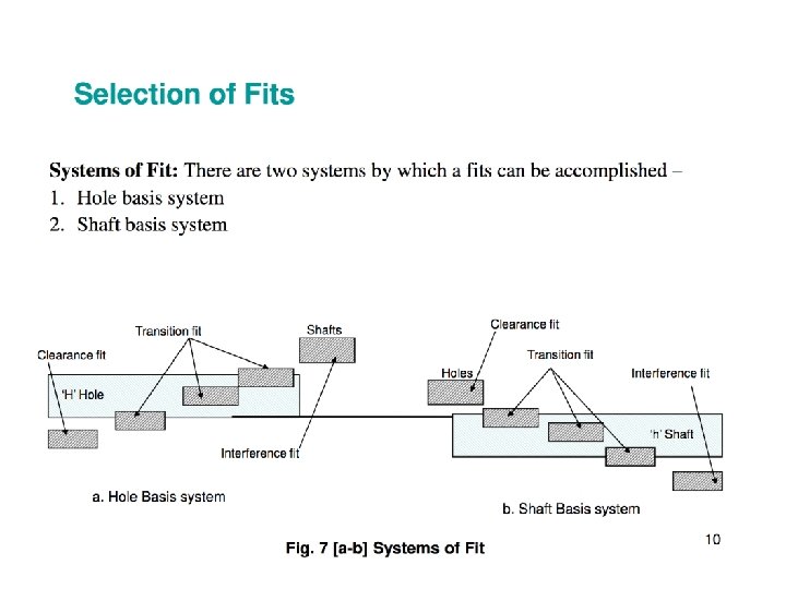
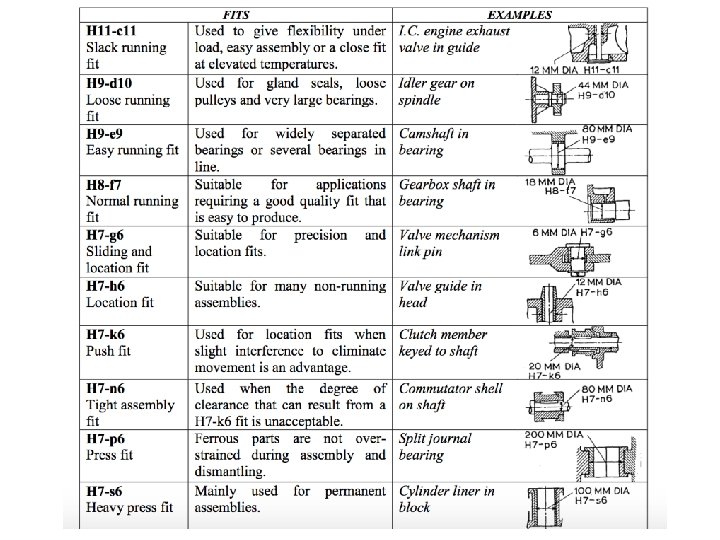
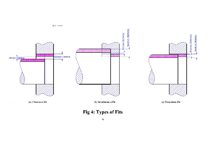
FITS Fits ü Manufactured parts are required to mate with one another during assembly. ü The relationship between the two mating parts that are to be assembled, that is, the hole and the shaft, with respect to the difference in their dimensions before assembly is called a fit. ü An ideal fit is required for proper functioning of the mating parts. Three basic types of fits can be identified, depending on the actual limits of the hole or shaft:
FITS 1. Clearance fit 2. Interference fit 3. Transition fit Clearance fit: The largest permissible diameter of the shaft is smaller than the diameter of the smallest hole. ü This type of fit always provides clearance. Small clearances are provided for a precise fit that can easily be assembled without the assistance of tools. When relative motions are required, large clearances can be provided, for example, a shaft rotating in a bush. ü In case of clearance fit, the difference between the sizes is always positive. The clearance fit is described in Fig. 3. 9.
FITS Interference fit: The minimum permissible diameter of the shaft exceeds the maximum allowable diameter of the hole. ü This type of fit always provides interference. Interference fit is a form of a tight fit. Tools are required for the precise assembly of two parts with an interference fit. üWhen two mating parts are assembled with an interference fit, it will be an almost permanent assembly, that is, the parts will not come apart or move during use. To assemble the parts with interference, heating or cooling may be required. üIn an interference fit, the difference between the sizes is always negative.
FITS
Transition Fit ü Transition fit: The diameter of the largest permissible hole is greater than the diameter of the smallest shaft and the diameter of the smallest hole is smaller than the diameter of the largest shaft. ü In other words, the combination of maximum diameter of the shaft and minimum diameter of the hole results in an interference fit, while that of minimum diameter of the shaft and maximum diameter of the hole yields a clearance fit. ü Since the tolerance zones overlap, this type of fit may sometimes provide clearance and sometimes interference, as depicted in Fig. 3. 11.
Allowance ü Allowance: An allowance is the intentional difference between the maximum material limits, that is, LLH and HLS (minimum clearance or maximum interference) of the two mating parts. It is the prescribed difference between the dimensions of the mating parts to obtain the desired type of fit. ü Allowance may be positive or negative. Positive allowance indicates a clearance fit, and an interference fit is indicated by a negative allowance. Allowance = LLH − HLS
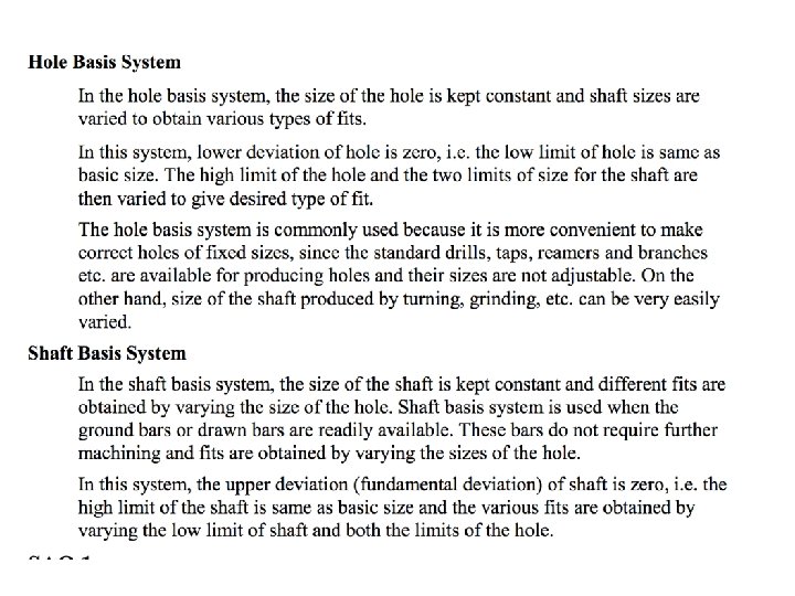
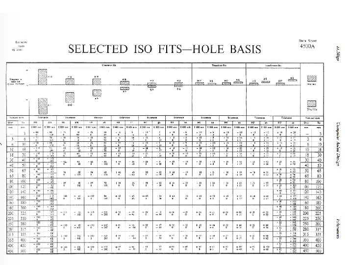
Hole & Shaft Basis System Hole Basis and Shaft Basis Systems To obtain the desired class of fits, either the size of the hole or the size of the shaft must vary. Two types of systems are used to represent the three basic types of fits, namely clearance, interference, and transition fits. They are (a) hole basis system and (b) shaft basis system. Although both systems are the same, hole basis system is generally preferred in view of the functional properties. Hole Basis System In this system, the size of the hole is kept constant and the shaft size is varied to give various types of fits. In a hole basis system, the fundamental deviation or lower deviation of the hole is zero, that is, the lower limit of the hole is the same as the basic size. The two limits of the shaft and the higher dimension of the hole are then varied to obtain the desired type of fit, as illustrated in Fig. 3. 13.
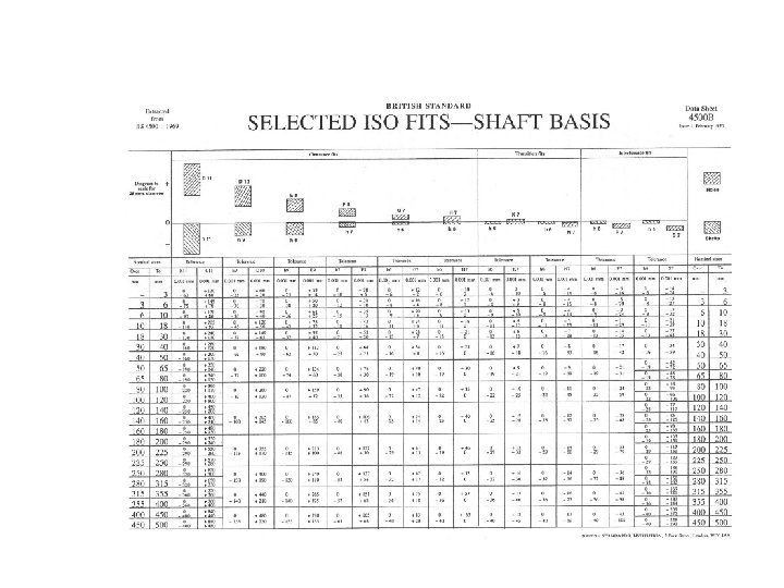
Shaft Basis System ü The system in which the dimension of the shaft is kept constant and the hole size is varied to obtain various types of fits is referred to as shaft basis system. ü In this system, the fundamental deviation or the upper deviation of the shaft is zero, that is, the HLH equals the basic size. The desired class of fits is obtained by varying the lower limit of the shaft and both limits of the hole, as shown in Fig. 3. 14.
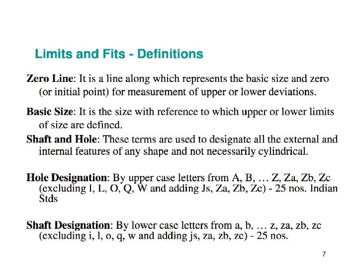
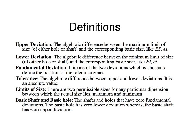
General Terminology in Fits ü Basic size: This is the size in relation to which all limits of size are derived. Basic or nominal size is defined as the size based on which the dimensional deviations are given. This is, in general, the same for both components. ü Limits of size: These are the maximum and minimum permissible sizes acceptable for a specific dimension. The operator is expected to manufacture the component within these limits. The maximum limit of size is the greater of the two limits of size, whereas the minimum limit of size is the smaller of the two. ü Tolerance: This is the total permissible variation in the size of a dimension, that is, the difference between the maximum and minimum limits of size. It is always positive. ü Allowance: It is the intentional difference between the LLH and HLS. An allowance may be either positive or negative. Allowance = LLH − HLS
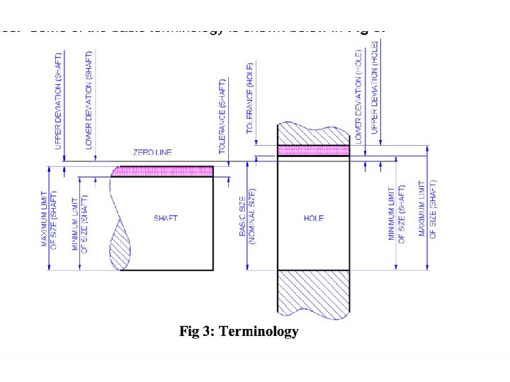
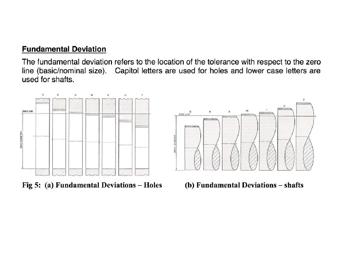
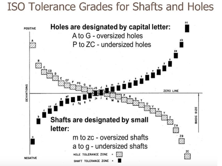
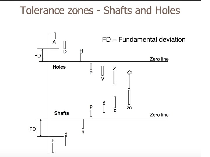
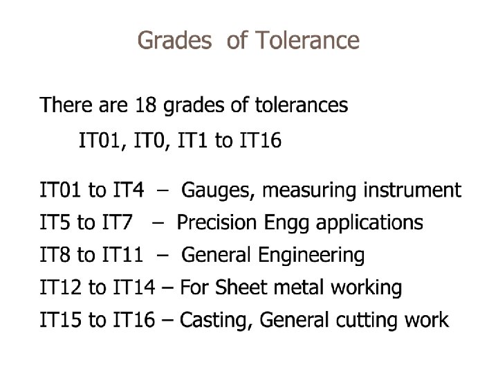
General Terminology in Fits Grade: This is an indication of the tolerance magnitude; the lower the grade, the finer the tolerance. Deviation: It is the algebraic difference between a size and its corresponding basic size. It may be positive, negative, or zero. Upper deviation: It is the algebraic difference between the maximum limit of size and its corresponding basic size. This is designated as ‘ES’ for a hole and as ‘es’ for a shaft. Lower deviation: It is the algebraic difference between the minimum limit of size and its corresponding basic size. This is designated as ‘EI’ for a hole and as ‘ei’ for a shaft. Actual deviation: It is the algebraic difference between the actual size and its corresponding basic size. Fundamental deviation: It is the minimum difference between the size of a component and its basic size. This is identical to the upper deviation for shafts and lower deviation for holes.
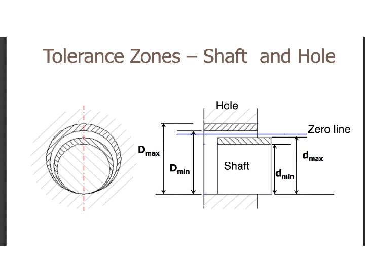
General Terminology in Fits ü Zero line: This line is also known as the line of zero deviation. The convention is to draw the zero line horizontally with positive deviations represented above and negative deviations indicated below. The zero line represents the basic size in the graphical representation. ü Shaft and hole: These terms are used to designate all the external and internal features of any shape and not necessarily cylindrical. ü Fit: It is the relationship that exists between two mating parts, a hole and a shaft, with respect to their dimensional difference before assembly.
General Terminology in Fits ü Maximum metal condition: This is the maximum limit of an external feature; for example, a shaft manufactured to its high limits will contain the maximum amount of metal. ü It is also the minimum limit of an internal feature; for example, a component that has a hole bored in it to its lower limit of size will have the minimum amount of metal removed and remain in its maximum metal condition, (i. e. , this condition corresponds to either the largest shaft or the smallest hole). ü This is also referred to as the GO limit. ü Least metal condition: This is the minimum limit of an external feature; for example, a shaft will contain minimum amount of material, when manufactured to its low limits. ü It is also the maximum limit of an internal feature; for example, a component will have the maximum amount of metal removed when a hole is bored in it to its higher limit of size, this condition corresponds to either the smallest shaft or the largest hole. ü This is also referred to as the NO GO limit.
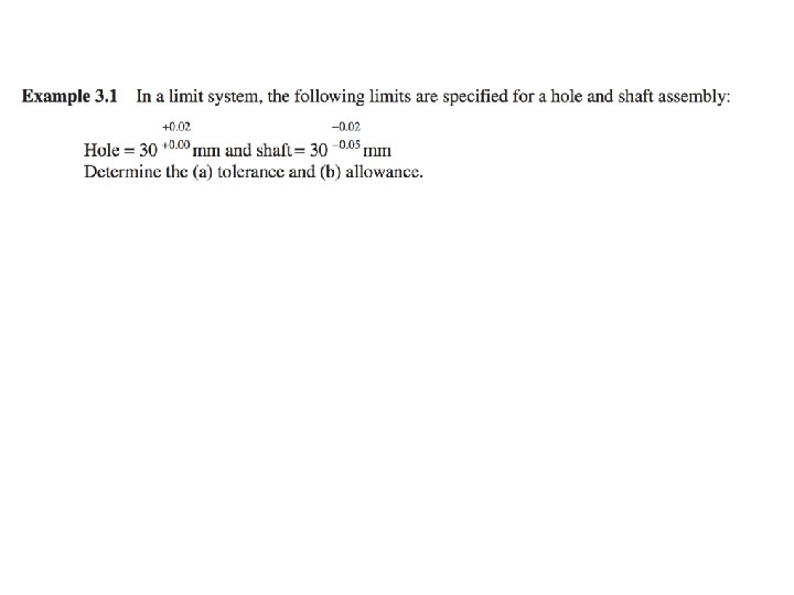
(a) Determination of tolerance: Tolerance on hole = HLH − LLH = 30. 02 − 30. 00 = 0. 02 mm Tolerance on shaft = HLS − LLS = [(30 − 0. 02) − (30 − 0. 05)] = 0. 03 mm (b) Determination of allowance: Allowance = Maximum metal condition of hole − Maximum metal condition of shaft =LLH − HLS = 30. 02 − 29. 98 = 0. 04 mm
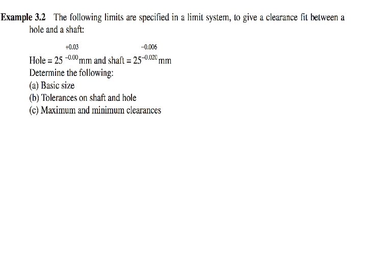
(a) Basic size is the same for both shaft and hole. (b) Determination of tolerance: Tolerance on hole = HLH − LLH = 25. 03 − 25. 00 = 0. 03 mm Tolerance on shaft = HLS − LLS = [(25 − 0. 006) − (25 − 0. 020)] = 0. 014 mm Determination of clearances: Maximum clearance = HLH − LLS = 25. 03 − 24. 98 = 0. 05 mm Minimum clearance = LLH − HLS = 25. 00 − (25 − 0. 006) = 0. 06 mm
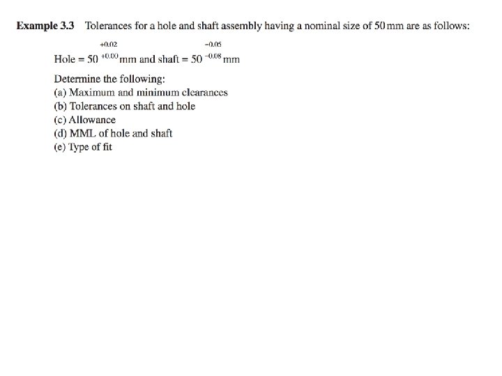
(a) Determination of clearances: Maximum clearance = HLH − LLS = 50. 02 − (50 − 0. 08) = 0. 10 mm Minimum clearance = LLH − HLS = 50. 00 − (50 − 0. 005) = 0. 05 mm (b) Determination of tolerance: Tolerance on hole = HLH − LLH = 50. 02 − 50. 00 = 0. 02 mm Tolerance on shaft = HLS − LLS = [(50 − 0. 05) − (50 − 0. 08)] = 0. 03 mm (c) Determination of allowance: Allowance = Maximum metal condition of hole − Maximum metal condition of shaft =LLH − HLS = 50. 00 − (50 − 0. 05) = 0. 05 mm (d) Determination of MMLs: MML of hole = Lower limit of hole = 50. 00 mm MML of shaft = Higher limit of shaft = 50. 00 − 0. 05 = 49. 05 mm (e) Since both maximum and minimum clearances are positive, it can be conclude that the given pair has a clearance fit.