Chapter 1 Limits Fits and Tolerances 1 Introduction


 30")
 31")
 32")

 34")
 35")
 36")
 37")

 39")
 40")
 41")


- Slides: 55
Chapter 1 Limits, Fits, and Tolerances 1
Introduction No two parts can be produced with identical measurements by any manufacturing process. In any production process, regardless of how well it is designed or how carefully it is maintained, a certain amount of natural variability will always exist. These natural variations are random in nature and are the cumulative effect of many small, essentially uncontrollable causes. Usually, variability arises from improperly adjusted machines, operator error, tool wear, and/or defective raw materials. 2
Introduction Such characteristic variability is generally large when compared to the natural variability. This variability, which is not a part of random or chance cause pattern, is referred to as ‘assignable causes’. Characteristic variations can be attributed to assignable causes that can easily be identified and controlled. If the process can be kept under control, that is, all the assignable and controllable causes of variations have been eliminated or controlled, the size variations will be well within the prescribed limits. 3
Introduction Some variability in dimension within certain limits must be tolerated during manufacture, however precise the process may be. The permissible level of tolerance depends on the functional requirements, which cannot be compromised. No component can be manufactured precisely to a given dimension; it can only be made to lie between two limits, upper (maximum) and lower (minimum). The designer has to suggest these tolerance limits, which are acceptable for each of the dimensions used to define shape and form, and ensure satisfactory operation in service. 4
Introduction When the tolerance allowed is sufficiently greater than the process variation, no difficulty arises. The difference between the upper and lower limits is termed permissive tolerance. For example, a shaft has to be manufactured to a diameter of 40 ± 0. 02 mm. This means that the shaft, which has a basic size of 40 mm, will be acceptable if its diameter lies anywhere between the limits of sizes, that is, an upper limit of 40. 02 mm and a lower limit of 39. 98 mm. Then permissive tolerance is equal to 40. 02 − 39. 98 = 0. 04. 5
Tolerances Tolerance can be defined as the magnitude of permissible variation of a dimension or other measured value from the specified value. It can also be defined as the total variation permitted in the size of a dimension, and is the algebraic difference between the upper and lower acceptable dimensions. It is an absolute value. The basic purpose of providing tolerances is to permit dimensional variations in the manufacture of components, adhering to the performance criterion as established by the specification and design. 6
Tolerances If high performance is the sole criterion, then functional requirements dictate the specification of tolerance limits; otherwise, the choice of setting tolerance, to a limited extent, may be influenced and determined by factors such as methods of tooling and available manufacturing equipment. The industry follows certain approved accuracy standards, such as ANSI (American National Standards Institute) and ASME (American Society of Mechanical Engineers), to manufacture different parts. 7
Tolerances Classification of Tolerance can be classified under the following categories: 1. Unilateral tolerance 2. Bilateral tolerance 3. Geometric tolerance Unilateral Tolerance When the tolerance distribution is only on one side of the basic size, it is known as unilateral tolerance. In other words, tolerance limits lie wholly on one side of the basic size, either above or below it. Example: + 0. 02 40 + 0. 01, + 0. 02 40 – 0. 00, – 0. 01 + 0. 00 40 – 0. 02, 40 – 0. 02 8
Tolerances 9
Tolerances Bilateral Tolerance When the tolerance distribution lies on either side of the basic size, it is known as bilateral tolerance. In other words, the dimension of the part is allowed to vary on both sides of the basic size but may not be necessarily equally disposed about it. Example: 40 ± 0. 02, + 0. 02 40 – 0. 01 10
Geometric Tolerance Geometric tolerances are used to indicate the relationship of one part of an object with another. 11
Tolerances Form tolerances: Form tolerances are a group of geometric tolerances applied to individual features. They limit the amount of error in the shape of a feature and are independent tolerances. Form tolerances as such do not require locating dimensions. These include straightness, circularity, flatness, and cylindricity. Orientation tolerances: Orientation tolerances are a type of geometric tolerances used to limit the direction or orientation of a feature in relation to other features. These are related tolerances. Perpendicularity, parallelism, and angularity fall into this category. Positional tolerances: Positional tolerances are a group of geometric tolerances that controls the extent of deviation of the location of a feature from its true position. This is a three‐dimensional geometric tolerance comprising position, symmetry, and concentricity. 12
Let LA = + 0. 02 30 – 0. 01 mm, LB = 20 + 0. 02 – 0. 01 mm and LC = 10 + 0. 02 – 0. 01 mm The overall length of the assembly is the sum of the individual length of components given as L = LA + LB + LC L = 30 + 20 + 10 = 60 mm 13
Then, cumulative upper tolerance limit is 0. 02 + 0. 02 =0. 06 mm and cumulative lower limit = – 0. 01 = – 0. 03 mm Therefore dimension of the assembled length will be = 60 + 0. 06 – 0. 03 mm It is essential to avoid or minimize the cumulative effect of tolerance build‐up, as it leads to a high tolerance on overall length, which is undesirable. If progressive dimensioning from a common reference line or a baseline dimensioning is adopted, then tolerance accumulation effect can be minimized. 14
Maximum and Minimum Metal Conditions Let us consider a shaft having a dimension of 40 ± 0. 05 mm. The maximum metal limit (MML) of the shaft will have a dimension of 40. 05 mm because at this higher limit, the shaft will have the maximum possible amount of metal. The shaft will have the least possible amount of metal at a lower limit of 39. 95 mm, and this limit of the shaft is known as minimum or least metal limit (LML). Similarly, consider a hole having a dimension of 45 ± 0. 05 mm. The hole will have a maximum possible amount of metal at a lower limit of 44. 95 mm and the lower limit of the hole is designated as MML. For example, when a hole is drilled in a component, minimum amount of material is removed at the lower limit size of the hole. This lower limit of the hole is known as MML. The higher limit of the hole will be the LML. At a high limit of 45. 05 mm, the hole will have the least possible amount of metal. 17
FITS Fits Manufactured parts are required to mate with one another during assembly. The relationship between the two mating parts that are to be assembled, that is, the hole and the shaft, with respect to the difference in their dimensions before assembly is called a fit. An ideal fit is required for proper functioning of the mating parts. Three basic types of fits can be identified, depending on the actual limits of the hole or shaft: 16
FITS 1. Clearance fit 2. Interference fit 3. Transition fit Clearance fit: The largest permissible diameter of the shaft is smaller than the diameter of the smallest hole. This type of fit always provides clearance. Small clearances are provided for a precise fit that can easily be assembled without the assistance of tools. When relative motions are required, large clearances can be provided, for example, a shaft rotating in a bush. In case of clearance fit, the difference between the sizes is always positive. 17
FITS Interference fit: The minimum permissible diameter of the shaft exceeds the maximum allowable diameter of the hole. This type of fit always provides interference. Interference fit is a form of a tight fit. Tools are required for the precise assembly of two parts with an interference fit. When two mating parts are assembled with an interference fit, it will be an almost permanent assembly, that is, the parts will not come apart or move during use. To assemble the parts with interference, heating or cooling may be required. In an interference fit, the difference between the sizes is always negative. 18
Allowance Allowance: An allowance is the intentional difference between the maximum material limits, that is, LLH and HLS (minimum clearance or maximum interference) of the two mating parts. It is the prescribed difference between the dimensions of the mating parts to obtain the desired type of fit. Allowance may be positive or negative. Positive allowance indicates a clearance fit, and an interference fit is indicated by a negative allowance. Allowance = LLH − HLS 19
Fit Types Type 1: Clearance fit = Occurs when two toleranced mating parts will always leave a space or clearance when assembled Type 2: Interference fit = Occurs when two toleranced mating parts will always interfere when assembled © Oxford University Press 2013. All rights reserved. 20
Fit Types Type 3: Transition fit = Occurs when two toleranced mating parts are sometimes and interference fit and sometimes clearance fit when assembled. 21
General Terminology in Fits Basic size: This is the size in relation to which all limits of size are derived. Basic or nominal size is defined as the size based on which the dimensional deviations are given. This is, in general, the same for both components. Limits of size: These are the maximum and minimum permissible sizes acceptable for a specific dimension. The operator is expected to manufacture the component within these limits. The maximum limit of size is the greater of the two limits of size, whereas the minimum limit of size is the smaller of the two. Tolerance: This is the total permissible variation in the size of a dimension, that is, the difference between the maximum and minimum limits of size. It is always positive. Allowance: It is the intentional difference between the LLH and HLS. An allowance may be either positive or negative. Allowance = LLH − HLS 22
General Terminology in Fits Grade: This is an indication of the tolerance magnitude; the lower the grade, the finer the tolerance. Deviation: It is the algebraic difference between a size and its corresponding basic size. It may be positive, negative, or zero. Upper deviation: It is the algebraic difference between the maximum limit of size and its corresponding basic size. This is designated as ‘ES’ for a hole and as ‘es’ for a shaft. Lower deviation: It is the algebraic difference between the minimum limit of size and its corresponding basic size. This is designated as ‘EI’ for a hole and as ‘ei’ for a shaft. Actual deviation: It is the algebraic difference between the actual size and its corresponding basic size. Fundamental deviation: It is the minimum difference between the size of a component and its basic size. This is identical to the upper deviation for shafts and lower deviation for holes. 25
General Terminology in Fits Zero line: This line is also known as the line of zero deviation. The convention is to draw the zero line horizontally with positive deviations represented above and negative deviations indicated below. The zero line represents the basic size in the graphical representation. Shaft and hole: These terms are used to designate all the external and internal features of any shape and not necessarily cylindrical. Fit: It is the relationship that exists between two mating parts, a hole and a shaft, with respect to their dimensional difference before assembly. 24
General Terminology in Fits 25
General Terminology in Fits • Basic Hole System – The basic hole system is used to apply tolerances to a hole and shaft assembly. 26
General Terminology in Fits Tolerance symbols: These are used to specify the tolerance and fits for mating components. For example, in 40 H 8 f 7, the number 40 indicates the basic size in millimeters; capital letter H indicates the fundamental deviation for the hole; and lower‐case letter f indicates the shaft. The numbers following the letters indicate corresponding ITgrades. 27
General Terminology in Fits 28
General Terminology in Fits 29
Clearance Fit (e. g. : H 7/f 6) 30
Clearance Fit (pl. H 7/f 6) 31
Clearance Fit (pl. H 7/f 6) 32
Transition Fit Either a clearance or an interference may result depending on the exact value of the dimensions of the machined shaft and hole within the specified tolerance zones. 33
Transition Fit (e. g. : H 7/j 6) 34
Transition Fit (e. g. : H 7/j 6) 35
Transition Fit (e. g. : H 7/j 6) 36
Transition Fit (e. g. : H 7/j 6) 37
Interference Fit The mating parts have such limits that the lowest shaft diameter is larger than the largest hole diameter. . 38
Interference Fit (H 7/n 6) 39
Interference Fit (H 7/n 6) 40
Interference Fit (H 7/n 6) 41
Two ways of indicating tolerances on technical drawings Limits of a dimension or the tolerance values are specified directly with the dimension. 42
Indicating tolerances The dimension is given by: • a shape symbol, • nominal size, • a letter indicating the position of the tolerance zone in relation to zero line, • a number indicating the width of the tolerance zone. 43
Specifying Fits in technical Drawing 44
Chapter 2 Couplings
Couplings Coupling is a device used to connect two shafts together at their ends for the purpose of transmitting power. Coupling Pump Motor
Uses of coupling ØTo provide connection of shafts of units made separately ØTo allow misalignment of the shafts or to introduce mechanical flexibility. ØTo reduce the transmission of shock loads. ØTo introduce protection against overloads. ØTo alter the vibration characteristics.
Types of coupling Ø Rigid Ø Flexible Ø Universal Rigid coupling Flexible coupling Universal coupling
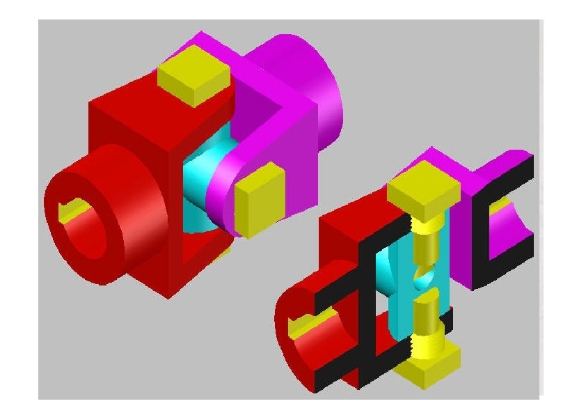
Rigid coupling Flange ØRigid couplings are used when precise shaft alignment is required Hub Key Driven Shaft ØSimple in design and are more rugged Ø Generally able to transmit more power than flexible couplings ØShaft misalignments cannot be compensated Driving Shaft Flanged Coupling
Flexible Coupling ØA flexible coupling permits with in certain limits, relative rotation and Ø variation in the alignment of shafts ØPins (Bolts) covered by rubber washer or bush is used connect flanges with nuts Flange Driving Shaft Driven Shaft Pin ØThe rubber washers or bushes act as a shock absorbers and insulators. Bush
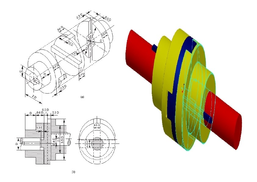
Universal Coupling ØIt is a rigid coupling that connects two shafts, whose axes intersect if extended. It consists of two forks which are keyed to the shafts. The two forks are pin joined to a central block, which has two arms at right angle to each other in the form of a cross (Fig. ). The angle between the shafts may be varied even while the shafts are rotating.
Oldham’s Coupling ØIt is used to connect two parallel shafts whose axes are at a small distance apart. Two flanges, each having a rectangular slot, are keyed, one on each shaft. The two flanges are positioned such that, the slot in one is at right angle to the slot in the other. To make the coupling, a circular disc with two rectangular projections on either side and at right angle to each other, is placed between the two flanges. During motion, the central disc, while turning, slides in the slots of the flanges. Power transmission takes place between the shafts, because of the positive connection between the flanges and the central disc.
Advantages and Limitations Advantages Torsionally stiff No lubrication or maintenance Good vibration damping and shock absorbing qualities Less expensive than metallic couplings More misalignment allowable than most metallic couplings Limitations Sensitive to chemicals and high temperatures Usually not torsionally stiff enough for positive displacement Larger in outside diameter than metallic coupling Difficult to balance as an assembly